
Specifications
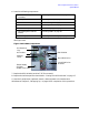


Chapter 2 77
Parts Replacement Procedures
LCD Display with Power Switch and Display Cable
LCD Display with Power Switch and Display Cable
This section explains how to remove and replace the LCD display assembly and the
Display Cable. Note that the power switch is part of the LCD display assembly.
WARNING Turn the workstation off and unplug the power cord before
removing or installing the LCD Display/Power Switch. Reference
“Safely Powering Down the B2000 Workstation” on page 12.
CAUTION To prevent damage to the B2000 workstation, observe all of the ESD
precautions described in “Electrostatic Discharge (ESD) Precautions” on
page 9.
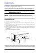
Removing the LCD Display/Power Switch Assembly
To remove the LCD assembly perform the following steps:
1. Open the front bezel as shown in the section “Opening the Front Bezel” on page 15.
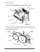
2. Unplug the LCD’s connector as shown in Figure 2-69.
Figure 2-69. Removing the LCD Display/Power Switch
3. Press inward on the mount clip located on the left side of the LCD mount and rotate the
left side of the LCD outward in a counterclockwise motion. See Figure 2-69. This action
releases the LCD’s right side mounting tab.
LCD Connector
LCD
Mount Tab
Mounting Clips
(right side)
(left side)