HP VISUALIZE B2000 UNIX® Workstations Parts Removal/Replacement Guide Manufacturing Part Number: HP Part No.
© Copyright 2000 Hewlett-Packard Company Notice UNIX is a registered trademark in the United States and other countries, licensed exclusively through X/Open Company Limited. The information contained in this document is subject to change without notice. Hewlett-Packard assumes no responsibility for the use or reliability of its software on equipment that is not furnished by Hewlett-Packard. This document contains proprietary information that is protected by copyright. All rights reserved.
Year 2000 Compliance This HP Year 2000 Warranty is in addition to the HP Standard Commercial Warranties contained in Exhibit E16, HP Terms and Conditions of Sale and Service.
Contents 1. Getting Started Safety Warnings. . . . . . . . . . . . . . . . . . . . . . . . . . . . . . . . . . . . . . . . . . . . . .9 Electrostatic Discharge (ESD) Precautions . . . . . . . . . . . . . . . . . . . . . . . .9 Replacement Part Kit Contents . . . . . . . . . . . . . . . . . . . . . . . . . . . . . . . .11 Required Tools . . . . . . . . . . . . . . . . . . . . . . . . . . . . . . . . . . . . . . . . . . . . . .11 Safely Powering Down the B2000 Workstation . . . . . . . . . . . . . . . . . .
Contents Hard Disk Drive . . . . . . . . . . . . . . . . . . . . . . . . . . . . . . . . . . . . . . . . . . . . Installing a Hard Disk Drive . . . . . . . . . . . . . . . . . . . . . . . . . . . . . . . . Removing a Hard Disk Drive . . . . . . . . . . . . . . . . . . . . . . . . . . . . . . . . Configuring a Hard Disk Drive as a File System . . . . . . . . . . . . . . . . 45 45 49 52 Power Supply . . . . . . . . . . . . . . . . . . . . . . . . . . . . . . . . . . . . . . . . . . . . . .
Contents Returning the Defective Exchange Assembly . . . . . . . . . . . . . . . . . . . . .
Contents 8
1 Getting Started The following important information must be adhered to for proper removal and replacement of all Hewlett-Packard parts. Safety Warnings WARNING Removing the device cover may expose sharp edges in the equipment chassis. To avoid injury, use care when installing customer add-on devices. NOTE Before performing removal/replacement procedures, position the workstation on a cushioned flat, stable surface, such as a table top or workbench.
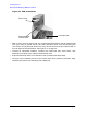
Getting Started Electrostatic Discharge (ESD) Precautions Figure 1-1. ESD Precautions Static Strap Strap attached to Bare Metal Antistatic Mat • Wear a static strap to ensure that any accumulated electrostatic charge is discharged from your body to ground. Attach the static-grounding wrist strap by following the instructions on the package. Attach the sticky end of the wrist strap to bare metal on the rear panel of the workstation. See Figure 1-1. on page 10.
Getting Started Replacement Part Kit Contents Replacement Part Kit Contents Take a moment to verify that your kit contains the following contents: • Part assemblies matching your order information. • Part Number: A3024-80004, Electrostatic Discharge (ESD) materials. • Removal/Replacement Instructions. • B2000 Owner’s Guide If you are missing any part or documentation, please call your designated service representative.
Getting Started Safely Powering Down the B2000 Workstation Safely Powering Down the B2000 Workstation You must complete the following steps before performing any of the removal and replacement procedures: NOTE Remove any accessory bag(s) and their black tab screws, if present, from the rear of the workstation. 1. Power off the workstation by simply pressing the power switch on the front panel of the workstation. Also, power off the monitor and any attached peripheral devices.
Getting Started Product Exploded Diagram Product Exploded Diagram Refer to the figure below for a basic parts overview of the B2000 workstation. Figure 1-3.
Getting Started Product Exploded Diagram 14 Chapter 1
2 Parts Replacement Procedures This section describes how to remove and replace components and assemblies in the B2000 workstation. Front Bezel and Left Side Panel Figure 2-1. Front Bezel Power Switch Latch Buttons Opening the Front Bezel Perform the following steps to open the workstation. 1. Power off the workstation and unplug the workstation. 2. Attach the static-grounding wrist strap by following the instructions on the package.
Parts Replacement Procedures Front Bezel and Left Side Panel Closing the Front Bezel Perform the following steps to close the workstation. 1. Locate the hinges on the left side of the front bezel, and insert them into the holes located along the left edge of the workstation. 2. Rotate the front bezel inward until you hear the two latch buttons snap in place. The front bezel is now closed. 3. Plug in the workstation’s power cord, and power on the workstation.
Parts Replacement Procedures Front Bezel and Left Side Panel 4. Grasp the back edge of the left side panel and rotate it outward approximately 30 degrees to the workstation. Next, pull the panel toward you as shown in Figure 2-2. This releases the panel’s top and bottom left side hook hinges from their hinge slots. See Figure 2-2.
Parts Replacement Procedures Memory DIMMs Memory DIMMs This section describes how to remove and replace the Memory DIMMs for the B2000 workstations. Installing Memory Perform the following steps to add memory (DIMM cards) to your workstation. WARNING Turn the workstation off and unplug the power cord before installing additional memory. Reference “Safely Powering Down the B2000 Workstation” on page 12.
Parts Replacement Procedures Memory DIMMs NOTE Reference the B2000 system label for the correct memory loading sequence. 2. Position the memory slots so they face you as shown in Figure 2-4. Note that Figure 2-4 also provides the loading sequence for the DIMM cards. This loading sequence must be maintained when you install the DIMM cards, but the size of the DIMM card put in each slot can vary.
Parts Replacement Procedures Memory DIMMs NOTE When installing memory, you need to orient the notches on the bottom edge of the DIMM card so that they are aligned with the keys on the DIMM connector. See Figure 2-6. The keyed DIMM connectors prevent you from installing the DIMM cards backwards. For referencing the DIMM loading sequence see the label on the chassis floor. See Figure 2-5. Figure 2-5. B2000 System Label Front of the B2000 workstation Memory Loading Sequence on B2000 System Label 4.
Parts Replacement Procedures Memory DIMMs Figure 2-6 Installing Memory Cards Step 1 Press down on ejector tabs to open them and place the DIMM card in the connector so that your fingers are on the edge of the DIMM card. Notches Step 2 Push the DIMM card down firmly and evenly into the connector to be sure it is properly seated. Black Ejector Tab White Ejector Tab 5. Place the DIMM card in the connector, lining it up with the guides.
Parts Replacement Procedures Memory DIMMs CAUTION To prevent damage to the B2000 workstation, observe all of the ESD precautions as described in the “Electrostatic Discharge (ESD) Precautions” on page 9. 1. Open the side panel of the workstation as explained in the section “Opening the Left Side Panel” on page 16 in this chapter. Figure 2-7 System Board View B2000 System Label Power Supply DIMM connectors Figure 2-8.
Parts Replacement Procedures Memory DIMMs 2. Press downward on the ejector tabs located on each side of the DIMM connector. See Figure 2-9. This raises the DIMM card for easy extraction. Figure 2-9 Removing Memory Cards Notches Ejector Tab 3. Lift up evenly on the outside edges of the DIMM card to remove it. See Figure 2-9. 4. Install the remaining DIMM cards in the correct order. See Figure 2-4 or the system label. 5.
Parts Replacement Procedures Memory DIMMs Memory Information Sample The following example shows the memory information when memory modules are properly installed and configured: MEMORY INFORMATION MEMORY STATUS TABLE Slot ---0 1 2 Size -----256MB 256MB 128MB Status ------------Active Active Active TOTAL MEMORY = 640MB MEMORY FAULT TABLE Slot ---- Size ------ Status ------------- Active, Installed Memory Deallocated Pages Available Memory : 640MB of SDRAM : 0 Pages ----------: 640MB Good Memory Requ
Parts Replacement Procedures PCI I/O Card(s) PCI I/O Card(s) This section describes how to remove and install I/O cards. Your B2000 workstation’s system board has four Peripheral Connect Interface (PCI) slots for option boards. Slots 1 and 2 are full-size PCI slots. Slots 3 and 4 are half-size PCI slots. Figure 2-10.
Parts Replacement Procedures PCI I/O Card(s) CAUTION If you are installing an additional graphics card, you must insert the fx card in Slot 1 for optimal performance. After you connect the monitor to the additional graphics card, you will need to change the graphics path for that monitor. To do this read the section “Displaying and Setting the Monitor Type” in the chapter “The Boot Console Interface” of your Owner’s Guide.
Parts Replacement Procedures PCI I/O Card(s) The steps required for removing an I/O card from the workstation are: 1. Power off the workstation, and unplug the workstation’s power cord from the electrical outlet. Note that when you press the workstation’s power switch, the workstation automatically performs a shutdown -h. 2. Open the side panel of the workstation as explained in the section “Opening the Left Side Panel” in this chapter. 3.
Parts Replacement Procedures PCI I/O Card(s) Installing I/O Cards To install an I/O card into your workstation, follow these steps. CAUTION To prevent damage to I/O cards, observe all of the ESD precautions as described in the “Electrostatic Discharge (ESD) Precautions” on page 9. NOTE The built-in VISUALIZE fxe graphics is the primary graphics slot and is referred to as slot 0.
Parts Replacement Procedures CD Drive CD Drive This section explains how to remove and replace the CD drive. Removing a CD Drive This section explains how to remove a CD drive from your workstation. WARNING Turn the workstation off and unplug the power cord before removing the CD drive. CAUTION CD drives are susceptible to mechanical and electronic shock. When handling the drive, always wear the static-grounding wrist strap that came in the CD drive kit. Always handle the drive carefully. 1.
Parts Replacement Procedures CD Drive Figure 2-16 Removing the CD Drive Bay’s EMI Shield Rear Cover EMI Shield Handle Audio Cable T-15 Torx/Slotted Screw Ferrite Bead ATAPI Cable Power Cable 3. Rotate the workstation around until you see the front of the unit as shown in Figure 2-17.
Parts Replacement Procedures CD Drive 4. Remove both CD drive bracket screws (T-15 Torx/slotted screws) and pull the CD drive out of the chassis assembly as shown in Figure 2-18. Figure 2-18 Removing the CD Drive Bracket Guide CD Drive Bracket Runner CD Drive Mounting Screws (T-15 Torx Screws) CD Drive Bracket Bracket Screws (T-15 Torx Screws) 5. Remove the four CD drive mounting screws (T-15 Torx/slotted screws) as shown in Figure 2-18 and remove the CD drive from the bracket.
Parts Replacement Procedures CD Drive your workstation, you must verify that the master/slave/CSEL jumper is set in the CSEL position. Since different manufacturers of CD drives have different locations for the CSEL jumper, look at the documentation that is supplied with your CD drive for the proper location of this jumper. CAUTION CD drives are susceptible to mechanical and electronic shock. When handling the drive, always wear the static-grounding wrist strap that came in the CD drive kit.
Parts Replacement Procedures CD Drive Figure 2-20 Front of Workstation with the Front Bezel Removed LCD Display Power Switch CD drive Blank Floppy Disk Blank 4. Remove both CD drive bracket screws (T-15 Torx/slotted screws) and pull the CD drive bracket out of the chassis assembly as shown in Figure 2-21. Next remove the four CD drive blank filler screws (T-15 Torx/slotted screws) as shown in Figure 2-21 and remove the blank filler from the bracket.
Parts Replacement Procedures CD Drive 5. Remove the CD drive from its shipping container and verify that the jumper on the back of the CD drive is set to the C Select position. Using the four blank filler screws (T-15 Torx/slotted screws) that were just removed, mount the disk drive to the bracket as shown in Figure 2-22. Note that the CD drive should extend approximately one inch out from the front of the CD drive bracket. Figure 2-22.
Parts Replacement Procedures CD Drive 7. Plug the audio, ATAPI and power cables into their appropriate connectors. Note that the connectors are keyed for proper insertion. To help with plugging in the audio connector, you can pull its cable through the back of the CD drive chassis to the front of the CD drive chassis and connect it. Note that you should connect the audio cable first. NOTE The red striped side of the data cable should be positioned next to the power cable. Figure 2-23.
Parts Replacement Procedures CD Drive 9. Make sure that the audio, ATAPI and power cables are positioned so that they come out of the bottom edge of the CD drive bay’s EMI shield. This edge is rounded to prevent cutting of the cables. See Figure 2-25. Next, secure the CD drive bay’s EMI shield using the T-15 Torx/slotted screw. When you replace the EMI shield, The ferrite bead on the ATAPI cable must remain outside of the CD drive bay’s EMI shield.
Parts Replacement Procedures Floppy Drive Floppy Drive Installing a Floppy Disk Drive Install the floppy disk drive by following the procedure covered in this section. Note that there are no jumper settings required for the installation of the floppy disk drive. WARNING Turn the workstation off and unplug the power cord before installing the floppy disk drive. CAUTION Floppy disk drives are susceptible to mechanical and electronic shock.
Parts Replacement Procedures Floppy Drive 3. Rotate the workstation around until you see the front of the workstation as shown in Figure 2-27. Figure 2-27 Front of Workstation with the Front Bezel Removed Floppy Drive Blank 4. Remove both floppy disk bracket screws (T-15 Torx/slotted screws) and pull the floppy disk bracket out of the chassis assembly as shown in Figure 2-28.
Parts Replacement Procedures Floppy Drive CAUTION Floppy disk drives are susceptible to mechanical and electronic shock. When handling the drive, always wear the static-grounding wrist strap that came in the floppy disk drive kit. Always handle the drive carefully. 5. Remove the floppy disk drive from its shipping container. Using the four T-15 Torx/slotted blank filler screws, mount the disk drive to the bracket as shown in Figure 2-29.
Parts Replacement Procedures Floppy Drive NOTE The red striped side of the floppy data cable is positioned toward the power cable. Figure 2-30. Plugging in the Floppy Data and Power Cables Power Cable Data Cable 8. Tighten the two T-15 Torx screws as shown in Figure 2-31.
Parts Replacement Procedures Floppy Drive 9. Verify that the floppy data and power cables are positioned so they come out of the top edge of the floppy disk drive bay’s EMI shield. This edge is rounded to prevent cutting of the cables. See Figure 2-32. Next, secure the floppy disk drive bay’s EMI shield using the T-15 Torx/slotted screw. When you replace the EMI shield, the ferrite bead on the data cable must remain inside of the floppy disk drive bay’s EMI shield.
Parts Replacement Procedures Floppy Drive Figure 2-33. Floppy Drive Removal: External T-15 Torx Screw T-15 Torx Screw 2. Facing the opened side of the workstation, remove the T-15 Torx screw that secures the back cover of the floppy drive bay, and then remove the back cover. Reach into the back of the floppy drive bay and disconnect the two cables: the floppy drive power cable and the ribbon cable. Disconnect these same cables from the system board and set them aside. Figure 2-34.
Parts Replacement Procedures Floppy Drive 3. Grasping the front of the floppy drive tray, gently pull it out of the front of the workstation. Figure 2-35.
Parts Replacement Procedures Floppy Drive Verifying the Floppy Drive Configuration To verify that your workstation can communicate with the floppy drive, use the ioscan command in a terminal window to see which devices are currently in use on your system. Note that you will have to be superuser or root to use the ioscan command.
Parts Replacement Procedures Hard Disk Drive Hard Disk Drive This section explains how to remove and replace the hard disk drive. Installing a Hard Disk Drive This procedure explains how to install your hard disk drive in the slot that has been preassigned to SCSI ID 5. On internal hard disk drives, the slot determines the addressing. There are no cables required when installing a hard disk drive. Note that to install the hard disk drive, your workstation must be turned off.
Parts Replacement Procedures Hard Disk Drive Figure 2-36 The Hard Drive Slots PCI Slots (4) Memory slots (4) Power Supply SCSI ID 6 SCSI ID 5 2. Loosen the captive T-15 Torx thumbscrew securing the disk drive bracket to the system board. As you grasp the tray and slide to the front of the workstation, the tray will unseat from the chassis rail. See Figure 2-37. You may need to angle the disk drive tray slightly to disengage the hooks as you slide it along the rail.
Parts Replacement Procedures Hard Disk Drive 3. Mount the hard disk drive on the hard drive bracket using the four T-15 Torx screws that are stored on the mounting bracket. See Figure 2-38. for location of the shoulder screws and Figure 2-39. for positioning the bracket to the hard disk drive. Figure 2-38. T-15 Torx Shoulder Screws T-15 Torx Screws (quantity 4) Figure 2-39.
Parts Replacement Procedures Hard Disk Drive 4. Insert the T-15 Torx Hard Disk Mounting Screws through the rubber mounting grommets and into the screw holes located on the hard disk drive. See Figure 2-40. Figure 2-40 Attaching the Hard Disk Drive T-15 Torx Shoulder Screw Mounting Grommets (do not remove) Hard Disk Drive Bracket Hard Disk Drive Bracket Hooks (quantity 4) 5.
Parts Replacement Procedures Hard Disk Drive 6. Replace the side panel as described in “Closing the Left Side Panel” on page 15. 7. Attach the USB keyboard, USB mouse, LAN, peripherals and power cord to the workstation. 8. Verify your installation procedure. See “Verifying System Operations” on page 85. Removing a Hard Disk Drive This procedure explains how to remove your hard disk drive. Note that there are no cables to disconnect when removing a hard disk drive.
Parts Replacement Procedures Hard Disk Drive Figure 2-43. Removing the Hard Disk Drive Captive T-15 Torx Thumbscrew 3. Remove the four T-15 Torx shoulder screws from the hard disk drive and bracket. See Figure 2-44. To avoid damaging the disk drive, you must carefully handle the disk drive when removing it from the workstation.
Parts Replacement Procedures Hard Disk Drive 4. Replace the four mounting screws on the hard disk drive bracket to store them for future use. Slide the mounting bracket into its hard drive slot, and push firmly inward to secure the hard drive bracket to the system board connector. Tighten the T-15 Torx thumbscrew to secure the bracket to the system board. See Figure 2-45. The side panel should now be replaced as explained in the section “Closing the Left Side Panel” on page 17 in this chapter.
Parts Replacement Procedures Hard Disk Drive Configuring a Hard Disk Drive as a File System This section describes how to add a hard disk drive to your workstation as a file system using SAM and how to remove the hard disk drive from your workstation. For more information about configuring a hard disk drive, refer to the manual Managing Systems and Workgroups. The procedures in this section require you to log in as root. If you cannot log in as root, contact your system administrator.
Parts Replacement Procedures Hard Disk Drive 4. Double click on the Sam icon in the Application Manager -- System_Admin window. If you are root, the System Application Manager (SAM) will appear on your screen. 5. Double click on the Disks and File Systems icon. 6. Double click on the Disk Devices icon. The following screen message is displayed: Scanning the system’s hardware... The Disks and File Systems window opens containing a list of drives installed in this workstation.
Parts Replacement Procedures Hard Disk Drive 8. Enter the mount directory name (for example, /disk1) in the Mount Directory field of the Add Disk without LVM window. 9. Click on the OK button in the Add Disk without LVM window. You will need to wait for a short time before the new file system is created and the hard disk drive is mounted. When the Add Disk without LVM window disappears and HFS appears in the Use column of the Disk and File Systems window, your task will be complete.
Parts Replacement Procedures Hard Disk Drive 4. Double click on the Sam icon in the Application Manager -- System_Admin window. If you are root, the System Application Manager (SAM) will appear on your screen. 5. Double click on the Disks and File Systems icon. 6. Double click on the Disk Devices icon. The following screen message is displayed: Scanning the system’s hardware... The Disks and File Systems window opens containing a list of devices installed in this workstation.
Parts Replacement Procedures Hard Disk Drive 7. Click on Remove in the Actions menu. In the window that next appears, click on the Yes button. This will unmount the file system located on the hard disk drive you are removing from the workstation. You will need to wait for a short time before the new file system is unmounted. The file system is successfully unmounted when you see Unused in the Use column.
Parts Replacement Procedures Power Supply Power Supply This section explains how to remove and replace the power supply. WARNING Always unplug the workstation’s power cord from the electrical outlet or power source before opening the workstation. Reference “Safely Powering Down the B2000 Workstation” on page 12. CAUTION To prevent damage to the B2000 workstation, observe all of the ESD precautions as described in the “Electrostatic Discharge (ESD) Precautions” on page 9. Removing the Power Supply 1.
Parts Replacement Procedures Power Supply 2. Remove the four T-15 Torx screws from the rear of the chassis. See Figure 2-47. Figure 2-47. Power Supply T-15 Torx Screws T-15 Torx Screws T-15 Torx Screws 3. Unplug the three power supply cables from the system board. See Figure 2-48. Figure 2-48. Power Supply Cables Power Supply Cables (3) Bundled Power Cables 4. Detach the bundled power cables from the cable management clip on the chassis floor. See Figure 2-48.
Parts Replacement Procedures Power Supply 5. Remove the T-15 Torx screw, EMI shield from the rear of the CD drive and disconnect the power cable. If the optional floppy drive is installed, you will need to repeat this step. See Figure 2-49. Grasp the EMI shield and swing out away from the rear of the CD drive or Floppy disk drive. Pull slightly outward to detach the hinged EMI shield from the slot in the CD or Floppy drive bay. Figure 2-49.
Parts Replacement Procedures Power Supply 6. Grasp the power supply and slide to the front of the workstation. You will need to disengage the hook (see Figure 2-50.) on the power supply from the support strap (see Figure 2-51.) in the chassis floor. Figure 2-50. Power Supply Hook Support Strap Power Supply Hook Figure 2-51.
Parts Replacement Procedures Power Supply Installing the Power Supply To install the power supply perform the following steps. 1. Grasp the power supply and position the external power cord connector facing the corresponding hole in the chassis. 2. Align the power supply hook with the support strap and slide the power supply to the rear chassis wall. The hook will slide into the support strap notch. See Figure 2-50. on page 60. 3.
Parts Replacement Procedures Power Supply 5. Clip the remaining power cable bundle into the cable management clip in the floor of the chassis. 6. Replace the four T-15 Torx screws for the power supply on the rear of the workstation. 7. Replace the left side panel. Reference “Closing the Left Side Panel” on page 17. 8. Attach all peripherals, keyboard, mouse, LAN and power cables to the workstation 9. Reference Chapter 3, “Wrapping Up,” on page 85 for completion of this procedure.
Parts Replacement Procedures Voltage Regulator Modules (VRMs) Voltage Regulator Modules (VRMs) This section explains how to remove and replace the voltage regulator modules (VRMs). WARNING Turn the workstation off and unplug the power cord before removing or installing voltage regulator modules. Reference “Safely Powering Down the B2000 Workstation” on page 12.
Parts Replacement Procedures Voltage Regulator Modules (VRMs) 2. Remove the four power supply T-15 Torx screws and slide the supply to unlatch from the support bracket. Without disconnecting the power cables, move the supply to the side. Figure 2-54. Power Supply T-15 Torx Screws T-15 Torx Screws (quantity 4) 3. Press outward on the ejector tabs located on each side of the VRM connectors. See Figure 2-55.
Parts Replacement Procedures Voltage Regulator Modules (VRMs) Installing VRMs To install VRMs follow these steps. 1. Perform all of the steps in “Removing VRMs”. You are ready to install new VRMs if your system looks like Figure 2-55. on page 64. 2. Carefully unpack the replacement VRMs and identify the Master and Slave. The notch in the VRM will align with the key in the connector. Also, the part number on the VRM distinguishes between Master and Slave. 3.
Parts Replacement Procedures System Board System Board This section describes how to remove and replace the system board. Removing the System Board WARNING Always unplug the workstation’s power cord from the electrical outlet or power source before opening the workstation. CAUTION To prevent damage to the B2000 workstation, observe all of the ESD precautions described in “Electrostatic Discharge (ESD) Precautions” on page 9. Perform the following steps to remove the System Board. 1.
Parts Replacement Procedures System Board Figure 2-56. B2000 Components PCI Retainer Clip Air Divider Memory Cards Power Supply & VRMs (hidden from view) Hard Disk Drive Hard Disk Drive Bracket 3. Unplug the following cables: • Speaker cable • LCD ribbon cable • PCI Fan cable • CD audio cable • CD drive data cable • Floppy drive data cable • System board fan cable Figure 2-57.
Parts Replacement Procedures System Board 4. Fold back the cables to avoid interference or damage before removal of the system board. 5. Remove the two T-15 Torx screws from the rear of the chassis. See Figure 2-58. Figure 2-58. System Board T-15 Torx Screws T-15 Torx Screws Note: No other screws need to be removed. CAUTION To avoid damaging the processor, do not use the turbo cooler fan housing as a handhold for removing the system board. 6.
Parts Replacement Procedures System Board 2. Angle the system board assembly diagonally as you begin installation. Position the system board flat inside the chassis. 3. Slide the system board slightly to the front and then to the rear of the workstation to engage the chassis wall hooks. Apply pressure to completely seat the system board. Figure 2-59. Installing the System Board Replacement 4. Insert and torque the two T-15 Torx screws that secure the system board to the rear of the chassis.
Parts Replacement Procedures System Board 5. Plug-in the following cables: • Speaker cable • LCD ribbon cable • PCI fan cable • CD audio cable • CD data cable • Floppy drive data cable • System fan cable Figure 2-61.
Parts Replacement Procedures System Board 6.
Parts Replacement Procedures Fans (I/O and System Board Fan) Fans (I/O and System Board Fan) This section explains how to remove and replace the I/O fan and the System Board Fan. WARNING Turn the workstation off and unplug the power cord before installing or removing fans. Reference “Safely Powering Down the B2000 Workstation” on page 12. CAUTION To prevent damage to the B2000 workstation, observe all of the ESD precautions described in “Electrostatic Discharge (ESD) Precautions” on page 9.
Parts Replacement Procedures Fans (I/O and System Board Fan) and rotate it about 15 degrees to the left. See the arrow in Figure 2-65. The fan and speaker bracket should now be free of the clip retainer hole and the bracket stop. Now move the whole mounting bracket to the left or toward the back of the CD Drive chassis. The fan and speaker mounting bracket is now free of the system unit. Figure 2-64.
Parts Replacement Procedures Fans (I/O and System Board Fan) Figure 2-65. Removing the Fan/Speaker Assembly from the I/O Area Fan Speaker Bracket Mounting Clip Speaker Cable Clips Fan Power Cable Bracket CD Drive Chassis Bracket Stop Mounting Clip Retainer Hole 5. To remove the speaker from the mounting bracket, push a finger through the access hole and spread the two retaining clips. The speaker will pop free of the mounting clips. Figure 2-66.
Parts Replacement Procedures Fans (I/O and System Board Fan) Installing the I/O Fan Perform the following steps to install the I/O fan: 1. Remove the replacement I/O fan assembly from the ESD protective packaging and inspect for the correct part match to your order. 2. Install the speaker in the replacement I/O fan assembly. See “Installing the Speaker” on page 81. 3. Align the housing fan bracket to the chassis support strut and the two locator tabs.
Parts Replacement Procedures Fans (I/O and System Board Fan) Installing the System Board Fan Perform the following steps to install the system board fan: 1. While grasping the fan with one hand, align the air flow arrow to point to the rear of the chassis. You will find the arrow molded on the edge of the fan. 2. Hold the fan flat to the rear of the chassis and align the mounting holes to the chassis. 3. Insert the flat head of the rivet(s) from the rear panel. Figure 2-68.
Parts Replacement Procedures LCD Display with Power Switch and Display Cable LCD Display with Power Switch and Display Cable This section explains how to remove and replace the LCD display assembly and the Display Cable. Note that the power switch is part of the LCD display assembly. WARNING Turn the workstation off and unplug the power cord before removing or installing the LCD Display/Power Switch. Reference “Safely Powering Down the B2000 Workstation” on page 12.
Parts Replacement Procedures LCD Display with Power Switch and Display Cable Installing the LCD Display/Power Switch Assembly For installation perform the following steps: 1. Open the front bezel as shown in the section “Opening the Front Bezel” on page 15. 2. Engage the right side of the LCD Display/Power switch assembly tab into the chassis slot. 3. Squeeze the left side clips while rotating the assembly into the chassis position. As the assembly is flush with the chassis, release the tab.
Parts Replacement Procedures Speaker Speaker This section describes how to remove and replace the workstation speaker. WARNING Turn the workstation off and unplug the power cord before removing or installing the speaker. Reference “Safely Powering Down the B2000 Workstation” on page 12. CAUTION To prevent damage to the B2000 workstation, observe all of the ESD precautions described in “Electrostatic Discharge (ESD) Precautions” on page 9. Removing the Speaker 1. Remove the workstation left side panel.
Parts Replacement Procedures Speaker Figure 2-71.
Parts Replacement Procedures Speaker Installing the Speaker WARNING Turn the workstation off and unplug the power cord before removing or installing the speaker. Reference “Safely Powering Down the B2000 Workstation” on page 12. CAUTION To prevent damage to the B2000 workstation, observe all of the ESD precautions described in “Electrostatic Discharge (ESD) Precautions” on page 9. NOTE Carefully position the cables to avoid damage while installing the fan/speaker bracket in the chassis.
Parts Replacement Procedures Real Time Clock Module (Battery) Real Time Clock Module (Battery) This section describes how to remove and replace the battery. WARNING Turn the workstation off and unplug the power cord before removing or installing the real time clock module. Reference “Safely Powering Down the B2000 Workstation” on page 12. CAUTION To prevent damage to the B2000 workstation, observe all of the ESD precautions described in “Electrostatic Discharge (ESD) Precautions” on page 9. 1.
Parts Replacement Procedures Real Time Clock Module (Battery) Figure 2-72.
Parts Replacement Procedures Real Time Clock Module (Battery) 84 Chapter 2
3 Wrapping Up This section contains information to help you confirm that your removal and replacement procedure was successful. In some cases you will need to use specific HP-UX commands and utilities to reconfigure the workstation to recognize the replacement part(s). Verifying System Operations To verify the system operation, follow these steps: 1. Reconnect the power cables and any other cables that were disconnected when opening the workstation. 2.
Wrapping Up Returning the Defective Exchange Assembly 86 Chapter 3
Index B Battery, 82 Bezel latch button, 15 M memory, 23 Memory card Installing, 18 Removing, 21 Memory configuration, displaying, 23 Memory information sample, 24 C CD drive Installing, 31 Removing, 29 P Power Supply, 57 Power Switch, 77 Powering off, 12 E EMI gasket, 17 ESD precautions, 9 F Fans, 72 floppy, 44 Floppy disk drive Installing, 37 Verifying configuration, 44 Front Bezel, 15 H Hard disk drive Configuring, 52 Installing, 45 Removing, 49 HP Year 2000 Warranty, 3 I I/O card Removing, 26 Slot n