
User's Manual

Virtual Connect modules 241
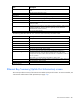
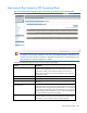
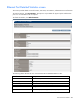
Row Description
OA Communication Status
Current Virtual Connect Manager to Onboard Administrator communication
state
Status Cause
Current interconnect status cause
Root Cause
Root cause of the interconnect status
Rack Name
Name of the enclosure rack (assigned through the Onboard Administrator)
Enclosure Name
Name of the enclosure (assigned through the Onboard Administrator)
Bay
Number of the bay being summarized on this screen
Module Host Name
Includes controls that enable you to set a custom host name for the module and
reset the module
Memory Module Usage
Displays the current memory usage of the module in kilobytes. Under normal
operating conditions, memory utilization generally remains below the
threshold value of 90% (red line).
Power Status/Control
Power state of the device
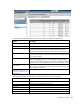
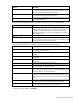
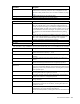
The following table describes the rows within the Interconnect Bay Information table.
Row Description
Part Number
The part number to be used when ordering an additional module of this type
Product Name
The common descriptive name of the module
IPv4 Address
IPv4 IP address of the module
IPv6 Address
IPv6 IP address of the module
Role
The role of the module (Primary or Subordinate)
Serial Number
The unique serial number of the module
Dip Switch Setting
The current physical setting of the system maintenance switches in a
hexadecimal format, where the least significant four bits of the value
correspond to the four switches and a bit value of 1 indicates the switch is in
the "on" position.
FIPS mode is on when the Dip Switch Setting is 0x4 or 0xE.
Spare Part Number
The part number to be used when ordering a replacement module of this type
Manufacturer
The manufacturer of the module
Firmware Version
The current firmware revision of the module
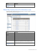
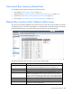
Ethernet Bay Summary (Uplink Port Information) screen
This screen provides a summary of the interconnect module uplink port information. To remove a module, see
"Interconnect module removal and replacement (on page 275)."