
User's Manual

Virtual Connect server profiles 190
If a server blade is present in the selected location, it must be powered off for the profile to be saved and
assigned properly.
For more information on server power requirements when assigning or removing server profiles, see
"Server profile troubleshooting (on page 285)."
Click Apply to save current changes and remain on this screen. Click Apply & Close to apply the
changes and go to the Server Profiles summary screen.
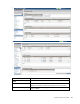
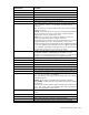
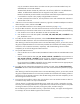
Creating FCoE HBA connections for a BL890c i4
Additional steps are necessary when a BL890c i4 is installed, and the enclosure has FCoE modules in bays
1 and 2. The figure below shows the first four connections created by default, plus four additional
connections that were added manually. The FCoE entries for I/O bays 1 and 2 (highlighted below) get
mapped to LOMs 1 and 2 on blades 1 and 2. The next pair of entries for I/O bays 1 and 2 would get
mapped to LOMs 1 and 2 on the third blade, and the fourth set of entries for I/O bays 1 and 2 would get
mapped to LOMs 1 and 2 on the fourth blade.
To have FCoE entries mapped to LOMs 3 and 4 on each blade in the server, you must add three extra sets
of FCoE entries, and then add the additional entries for I/O bays 1 and 2. See ports 17-24 in the figure
below.
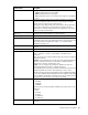
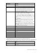
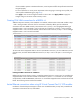
Creating FCoE HBA connections for a BL870c i4
Referencing the previous figures, entries 1-8 would be mapped as shown. Entries 9 and 10 would then be
mapped to LOMs 3 and 4 on the first blade in the BL870c i4, entries 11-12 would be as in this example
except that they would be UNMAPPED, and entries 13-14 would be mapped to LOMs 3 and 4 on the second
blade. The remaining entries would not be needed.
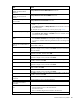
Limited Ethernet connections when using HP Virtual Connect Flex-10/10D modules
Introduction of the dual-hop FCoE support in VCM v4.01 enabled the ability to map newly created FCoE
connections to the HP VC Flex-10/10D module.