
User's Manual

Virtual Connect networks 143
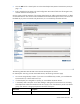
Field name Description
Connection Mode
Connection mode of the uplink ports for this network. For a description of the
connection modes, see "Defining a shared uplink set (on page 137)." This
mode cannot be changed for shared uplink sets using an associated FCoE
network.
LACP Timer
Applicable if Connection Mode is Auto. Shows the LACP timer configuration
for this network. This setting controls the requested frequency of LACP control
messages on a LACP capable interface. The domain default option shows
the current default.
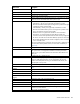
The following table describes the available actions in the Edit Shared Uplink Set screen. Clicking another link
in the pull-down menu or left navigation tree causes current edits that have not been applied to be lost.
Task Action
Rename shared uplink set
Click on the uplink set name and edit. Click Apply.
Add an external port
Use the cascading menu to select a port.
Set the Port Role to primary or
secondary
Click the down arrow in the Port Role column and select Primary or
Secondary. Only available if the connection mode is set to Failover. This
setting cannot be changed for shared uplink sets with an associated FCoE
network.
Change the uplink interface port
speed or disable a port
Click the pull-down box under Speed/Duplex, and then select a setting. For
shared uplink sets with an associated FCoE network, this setting is always
Auto.
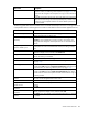
Delete a port
Click the Delete link in the Action column, or left-click to select a port,
right-click to display a menu, and then select Delete Port.
Change connection mode
Select Auto or Failover. For shared uplink sets with an associated FCoE
network, this setting is unavailable.
Change the LACP timer
Select Domain Default, Short, or Long for the LACP timer.
Add an associated FCoE network
Click Add in the table. For more information, see "Defining an FCoE network
(on page 139)."
Add a single associated network
Click Add above the table, or right-click on the header row to display a menu,
and then select Add. Select the a single Associated Network radio button. For
more information, see "Defining a shared uplink set (on page 137)."
Add multiple associated networks
Click Add above the table, or right-click on the header row to display a menu,
and then select Add. Select the multiple Associated Networks radio button,
and then enter the network name prefix and suffix and the VLAN ID ranges in
the fields provided.
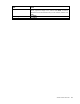
Enabled native VLAN on the
network
Edit the associated network properties and select the box next to Native. Only
one VLAN can be designated as the native VLAN.
Enable Smart Link on the Network
Edit the associated network properties and select the box next to Smart Link.
Designate the network as a
private network
Edit the associated network properties and select the box next to Private
Network.
Edit associated FCoE network
properties
Click Edit.
Edit associated network
properties
Click the Edit link in the Action column, or left-click to select an associated
network, right-click to display a menu, and then select Edit.
Delete an associated FCoE
network
Click Delete. You cannot delete an associated FCoE network if it is assigned
to a profile.