
User's Manual
Virtual Connect networks 138
o Domain Default—If this mode is selected, the network uses the domain-wide LACP timer
configuration setting. The current setting is displayed as part of the radio button label. See the
descriptions for Short and Long.
o Short—If this mode is selected, VC requests short (every 1 second) LACP control messages on a LAG
that is formed with the uplink ports.
o Long—If this mode is selected, VC requests long (every 30 seconds) LACP control messages on a
LAG that is formed with the uplink ports.
6. Create the associated FCoE networks that will use this shared uplink. For more information, see
"Defining an FCoE network (on page 139)."
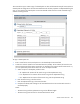
7. Create the Associated Networks that will use this shared uplink:
a. Click Add above the table.
-or-
Right-click the header row in the Associated Networks table to display a menu, and then select Add.
b. To add a single associated network:
i. Select the a single Associated Network radio button.
ii. Enter the name of the network.
iii. Enter the number for the VLAN ID (1 to 4094) for that network as defined by the network
administrator and as configured on the external Ethernet switch.
iv. Select whether to enable (check box selected) or disable (check box cleared) native VLAN. Only
one network per shared uplink set can be selected as the native VLAN. See "Shared uplink sets
and VLAN tagging (on page 86)."
v. Skip to step d.
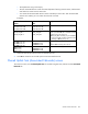
c. To add multiple associated networks:
i. Select the multiple Associated Networks radio button. Creating multiple associated networks in
bulk allows for a shorter setup time. All networks created in bulk share the same settings. These
networks can be edited individually after they are created.
ii. Enter the name of the networks. The networks that are created together share a common naming
convention of a prefix, the VLAN ID, and a suffix. The prefix and suffix are both optional.
iii. Enter comma separated VLAN IDs, VLAN ID ranges, or a mixture of both. For example, enter
3,9,15-20 to create eight associated networks with the VLAN IDs 3, 9, 15, 16, 17, 18, 19,
and 20.
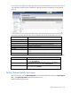
d. To add a color to the network, select a color from the Color pull-down menu. The network color is
used as visual identifier for the network within VCM.
e. To add labels to the network, type a label in the Labels field, and then press Enter. Labels are used
as text-based identifiers for the network within VCM. Each label can contain up to 24 characters,
excluding spaces. Each network can have up to 16 labels.
f. Select whether to enable (check box selected) or disable (check box cleared) Smart Link (on page
87).
g. Select whether to designate (check box selected) or not designate (check box cleared) the network
as a private network ("Private Networks" on page 87).
h. To set the preferred or maximum connection speed, select the Advanced Network Settings check
box.
To change these settings: