
User's Manual

Virtual Connect networks 135
• In VC 4.30 and later, the VLAN Capacity (on page 98) places restrictions on the number of networks
that can be added to a shared uplink set.
• If the domain stacking mode is configured with horizontal or primary slice stacking links, only uplink
ports on the same logical interconnect can be added.
o Based on the first uplink port selected, the list of external uplink ports is filtered to display only ports
in the same logical interconnect.
o Remove all uplink ports to reset the filtering.
For more information on the domain stacking mode, see "Stacking links ("Stacking Links screen" on
page 231)."
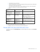
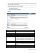
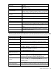
The following table describes the fields within the Define Shared Uplink Set screen.
Field name Description
Ethernet Shared External Uplink
Set
Uplink Set Name
Descriptive name for the shared uplink set. Do not use spaces.
External Uplink Ports
Port
Enclosure, bay, and port number
Port Role
Displays whether the port is designated as primary or secondary. For shared
uplink sets with an associated FCoE network, the port role is N/A.
Port Status
Shows the link status, link speed, and connectivity of the port. If the port is
unlinked and no connectivity exists, the cause is displayed. For more
information about possible causes, see "Port status conditions (on page
274)."
Connector Type
The type of connector on the port; for example, RJ-45
Connected To
If the individual port is connected to a switch that supports LLDP, the switch
LLDP system name or management IP address and switch port number
appear. A link is provided to obtain more information about the far-end
switch port.
PID
PID status icon (on or off) for the port
Speed/Duplex
Pull-down menu to specify the speed and duplex (where applicable) of the