
Setup and Install

HP Virtual Connect Manager 79
o
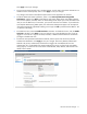
Set preferred connection speed. This value is the default speed for server profile connections
mapped to this network. The server administrator can increase or decrease this setting on an
individual profile connection. This setting is used for the minimum bandwidth.
o Set maximum connection speed. This value is the maximum speed for server profile connections
mapped to this network. This setting limits the maximum port speed from the server to the network
connection associated with the multiple networks. Maximum bandwidth is determined by the
maximum connection speed of the network. All multiple networks share the same maximum
connection speed.
The availability of the 20Gb setting is dependent on 20Gb NICs and HP VC FlexFabric-20/40 F8
Modules being present in the domain.
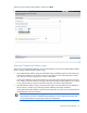
2. Click Apply.
Virtual Connect can control link speed for FlexNICs only when they are connected to an HP Virtual Connect
Enet Module. Virtual Connect cannot control the link speed of traditional NICs.
IMPORTANT: Each FlexNIC and FlexHBA is recognized by the server as a PCIe physical function
device with adjustable speeds from 100 Mb to 10 Gb in 100 Mb increments when connected to
an NC553i/m 10Gb 2-port FlexFabric FlexFabric Adapter or any Flex-10 NIC. For NC551i/m
Dual Port FlexFabric 20 Gb FlexFabric Adapters, the range is limited to 1 Gb to 20 Gb in 100 Mb
increments.
For more information on FlexNICs, see the HP Virtual Connect for c-Class BladeSystem User Guide on the HP
website (http://www.hp.com/go/vc/manuals).
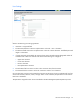
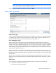
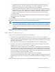
Select Network Connection Type
To begin, select one of the following external network connections:
• Connection with uplink(s) dedicated to a single network ("Define Single Network" on page 80)
Select this option to define a network within the Virtual Connect environment and identify any module
uplink ports used to connect to that network in the data center. Internal-only networks (without external
uplinks) can also be defined.
These single networks pass through any VLAN tags added by the server or added externally.
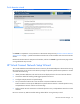
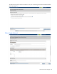
• Connection with uplink(s) carrying multiple Ethernet networks and/or FCoE networks (using VLAN
tagging) ("Define Shared Uplink Set Connection" on page 83)
Select this option to define multiple networks, FCoE networks, or both that all share a common set of
module uplink ports within the Virtual Connect environment. Network traffic from each network within
the Virtual Connect environment receives a VLAN tag as it exits on a shared uplink port. Virtual Connect
uses the VLAN tag on incoming network traffic to place it on the appropriate internal network. Ethernet
VLAN tags are added on egress and stripped on ingress.
Avoid using this type of network connection when the server inserts VLAN tags.
One network can be designated as a native VLAN, causing all untagged incoming Ethernet packets to
be placed on this network. For more information, see "Shared uplink sets and VLAN tagging" in the user
guide.
After each network is defined, you have the option to define additional networks or finish the wizard.