
Setup and Install

Installation 27
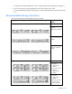
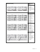
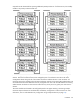
Single enclosure stacking Modules (top to
bottom)
•
HP Virtual Connect
FlexFabric
10Gb/24-port
Modules
•
HP Virtual Connect
FlexFabric
10Gb/24-port
Modules
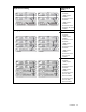
•
HP Virtual Connect
Flex-10 10Gb
Ethernet Modules
•
HP Virtual Connect
FlexFabric-20/40 F8
Modules
The 1000BASE-T links can be used as stacking links of up to 100 m (328 ft). Ports with different connector
types can be aggregated if the link speed is the same. For example, CX4 and SFP+ ports both running at
10G can be aggregated to provide enhanced throughput for the stacking link.
NOTE: The CX4 interface uses the same physical connector as InfiniBand, but InfiniBand cables
are tuned differently and will not perform as well in CX4 applications. HP recommends
purchasing CX4 cable assemblies that meet the IEEE CX4 specifications and support 10-Gigabit
communication at distances from 3 m to 15 m (9.84 ft to 49.20 ft).
For information on supported cables, see the module QuickSpecs on the HP website
(http://www.hp.com/go/vc/manuals).
HP strongly recommends full redundancy of VC-Enet modules. The recommended stacking configurations
have redundant connections. If a stacking cable is disconnected or fails, the Ethernet packets within the
Virtual Connect domain are automatically re-routed to the uplink through the redundant path. This
configuration helps preserve network connectivity if an Ethernet interconnect module fails or is removed.
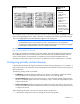
Configuring partially stacked domains
A partially stacked domain uses logical interconnects to create stacking configurations in a VC domain. A
logical interconnect is the combination of horizontally adjacent Enet modules and the internal stacking link
that connects them.
The following stacking modes are available:
• Full Stacking is the default stacking mode for the VC domain. In Full Stacking, all Ethernet modules
within the domain are connected by horizontal cross connects or by stacking cables.
• Horizontal Stacking disables all vertical stacking links. In horizontal stacking mode, each horizontal
bay pair is a separate logical interconnect. For example, if bay 1 and bay 2 are populated, they form
a logical interconnect.
• Primary Slice Stacking disables all stacking links outside of the primary slice. The primary slice is the
primary and standby interconnect modules for the enclosure. In primary slice stacking, the primary slice
is a logical interconnect.
When configuring horizontal or primary slice stacking, observe the following:
• A brief network outage occurs when you change the domain stacking mode.