3Com® Telecommuting Module Installation Guide Version 4.
3Com® Telecommuting Module Installation Guide: Version 4.3 Part Number BETA Published December 2005 3Com Corporation, 350 Campus Drive, Marlborough MA 01752-3064 Copyright © 2005, 3Com Corporation. All rights reserved. No part of this documentation may be reproduced in any form or by any means or used to make any derivative work (such as translation, transformation, or adaptation) without written permission from 3Com Corporation.
Table of Contents Part I. Installation of the 3Com VCX IP Telecommuting Module ......................................................................... i 1. Introduction .....................................................................................................................................................1 2. Overview of the Installation ............................................................................................................................3 3.
Part I. Installation of the 3Com VCX IP Telecommuting Module This document will help you to get started with your 3Com VCX IP Telecommuting Module. It contains the necessary information to configure your Telecommuting Module. Additional information about managing your 3Com VCX IP Telecommuting Module can be found in the User Manual.
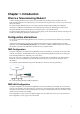
Chapter 1. Introduction What is a Telecommuting Module? A Telecommuting Module is a device which processes traffic under the SIP protocol (see RFC 3261). The Telecommuting Module receives SIP requests, processes them according to the rules you have set up, and forwards them to the receiver. The Telecommuting Module connects to an existing enterprise firewall through a DMZ port, enabling the transmission of SIP-based communications without affecting firewall security.
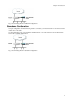
Chapter 1. Introduction Fig 2. Telecommuting Module in DMZ/LAN configuration. Standalone Configuration Using this configuration, the Telecommuting Module is connected to your internal network on one interface and the outside world on the other. Use this configuration only if your firewall lacks a DMZ interface, or for some other reason cannot be configured for the DMZ or DMZ/LAN alternatives. Fig 3. Telecommuting Module in Standalone configuration.
Chapter 2. Overview of the Installation Quick guide to 3Com VCX IP Telecommuting Module installation 3Com VCX IP Telecommuting Module is easy to install: • Select an IP address for the Telecommuting Module on your network. • The network interfaces are marked with 1 and 2. These numbers correspond to the physical interfaces eth0 and eth1 respectively, the latter which should be use in the installation program. • Plug in the power cord and turn on the Telecommuting Module.
Chapter 2. Overview of the Installation • If you use a dialing domain which looks like an IP address, enter the dialing domain in the Translation exceptions table. See also the Interoperability section. • For this type of dialing domain, you also need to go to the Routing page. Enter the dialing domain in the DNS Override For SIP Requests table and state the IP address of the SIP server(s) to handle the domain. See also the Routing section. • Go to the Save/Load Configuration page under.
Chapter 2. Overview of the Installation License Conditions To fulfill the license conditions, we must either attach the source code with the software, or send a written offer, valid at least three years, to give a copy of the source code to anyone who wants it. According to 3b) of the license, we are entitled to charge for the distribution of the source code. 3Com Corporation offer the source code for all third party software included in 3Com VCX IP Telecommuting Module and licensed under GPL.
Chapter 3. Installing 3Com VCX IP Telecommuting Module Installation There are three ways to install an 3Com VCX IP Telecommuting Module: using a serial cable, using a diskette or perform a magic ping. Installation with a serial cable or a diskette requires being at the same place as the Telecommuting Module, but will give more options for the start configuration.
Chapter 3. Installing 3Com VCX IP Telecommuting Module • Ping this IP address to give the Telecommuting Module its new IP address. You should receive a ping reply if the address distribution was successful. • Configure the rest through a web browser. Installation with a serial cable These steps are performed when installing with a serial cable: • Connect the Telecommuting Module to your workstation with a null modem serial cable. • Plug in the power cord and turn the Telecommuting Module on.
Chapter 3. Installing 3Com VCX IP Telecommuting Module Then enter a password for the Telecommuting Module. This is the password you use in your web browser to access and change the Telecommuting Module’s configuration. Finally, you can reset all other configuration if you want to. Following is a sample run of the installation program. 3Com VCX IP Telecommuting Module Administration 1. Basic configuration 2. Save/Load configuration 3. Become a failover team member 4.
Chapter 3. Installing 3Com VCX IP Telecommuting Module The installation program then asks for the network number. The network number is the lowest IP address in the series of numbers that includes the configuration computers (see chapter 3 of the User Manual). The network mask determines the number of computers that can act as configuration computers. Network number [0.0.0.0]: 10.47.2.0 Netmask/bits [255.255.255.0]: 255.255.255.
Chapter 3. Installing 3Com VCX IP Telecommuting Module You have now entered the following configuration Network configuration inside: Physical device name: eth0 IP address: 192.168.150.2 Netmask: 255.255.255.0 Deactivate other interfaces: no Computer allowed to configure from: IP address: 192.168.128.3 Password: eeyore The rest of the configuration is kept.
Chapter 3. Installing 3Com VCX IP Telecommuting Module Following is a sample run of the installation program on the diskette. Basic unit installation program version 4.3 Press return to keep the default value Network configuration inside: Physical device name[eth0]: IP address [0.0.0.0]: 10.47.2.242 Netmask/bits [255.255.255.0]: 255.255.0.0 Deactivate other interfaces? (y/n) [n] Computers from which configuration is allowed: You can select either a single computer or a network.
Chapter 3. Installing 3Com VCX IP Telecommuting Module Static routing: The network allowed to configure from is not on a network local to this unit. You must configure a static route to it. Give the IP address of the router on the network this unit is on. The IP address of the router [0.0.0.0]: 10.47.3.1 Network address [10.47.0.0]: 10.10.0.0 Netmask [255.255.255.0]: Then enter a password. Password []: Finally, you are asked if you want to reset other configuration.
Chapter 3. Installing 3Com VCX IP Telecommuting Module Remember to lock up the Telecommuting Module The Telecommuting Module is a computer with special software, and must be protected from unauthorized physical access just as other computers performing critical tasks. A locked up Telecommuting Module protects against: • connecting to the console • connecting a keyboard and monitor • changing the administrator password using the installation diskette.
Part II. Configuring 3Com VCX IP Telecommuting Module These chapters contain information about how to configure your 3Com VCX IP Telecommuting Module, once it has been installed. All configuration is made through the web interface of the Telecommuting Module. The configuration described in these chapters is basic for making the Telecommuting Module work. For descriptions of more advanced Telecommuting Module functions, please refer to the User Manual.
Chapter 4. Network Configuration First, the Telecommuting Module must be configured to be aware of the network in which it operates. This is performed on the Network pages. The important pages for getting started are Telecommuting Module Type, Interface (Network Interface 1 and 2), Networks and Computers and (for the DMZ Telecommuting Module Type) Surroundings. You will also need to add configuration on the Basic Configuration page under Basic Configuration.
Chapter 4. Network Configuration On your firewall, you need to open the SIP port (normally UDP port 5060) and a range of UDP ports for RTP traffic between the Telecommuting Module and the Internet. The other interface is connected to your internal network. The Telecommuting Module can handle several networks on the internal interface even if they are hidden behind routers. No networks on other interfaces on the firewall can be handled.
Chapter 4. Network Configuration Basic Configuration On the Basic Configuration page, general settings for the Telecommuting Module are made. The most important ones for getting started are the default gateway and, for SIP, the DNS server. General Name of this Telecommuting Module Here, you can give your 3Com VCX IP Telecommuting Module a name. The name of the Telecommuting Module is displayed in the title bar of your web browser. This can be a good idea if you administer several Telecommuting Modules.
Chapter 4. Network Configuration DNS name or IP address Enter the DNS name or IP address for the default gateway. If an interface will receive its IP address from a DHCP server, the Telecommuting Module will get its default gateway from the server, and Default Gateway must be set to "*". IP address Shows the IP address of the DNS name or IP address you entered in the previous field.
Chapter 4. Network Configuration No. The DNS servers are used in the order they are presented in the table. To move a server to a certain row, enter the number on the row to which you want to move it. You need only renumber servers that you want to move; other servers are renumbered automatically. When you click on Save, the DNS servers are re-sorted. DNS Name Or IP Address The DNS name/IP address of the DNS server which the Telecommuting Module should use.
Chapter 4. Network Configuration Status Specify if this network interface is On or Off. If the interface is off, all configuration on this page is ignored, and the Telecommuting Module will behave as if this interface wasn’t present (except when used for failover). If the interface should be used for failover, you should select Off. In this case, it won’t be available for other traffic than the synchronizing within the failover team. Read more about failover in chapter 12 of the User Manual.
Chapter 4. Network Configuration Delete Row If you select this box, the row is deleted when you click on Add new rows, Save, or Look up all IP addresses again. Create Enter the number of new rows you want to add to the table, and then click on Create. Alias 3Com VCX IP Telecommuting Module can use extra IP addresses, aliases, on its interfaces. All alias IP addresses must belong to one of the Directly Connected Networks you have specified. Aliases are necessary for setting up a STUN server.
Chapter 4. Network Configuration Routed network Enter the DNS name or IP address of the routed network under DNS name or network address. The IP address of the routed network is shown under Network address. In the Netmask field, enter the netmask of the network. Router The name or IP address of the router that will be used for routing to the network. If there are several routers between the Telecommuting Module and the network, fill in the router closest to the Telecommuting Module.
Chapter 4. Network Configuration When using an already defined group as a subgroup, select the name of the group under Subgroup. Set Interface/VLAN to ’-’ and leave the other fields empty. Name Enter a name for the group of computers. You can use this name when you change configuration on the pages mentioned above. A group can consist of several rows of IP addresses or series of IP addresses.
Chapter 4. Network Configuration For computers in an IP range that you want to give a network name, enter the last IP address in the range. The IP address in Upper Limit must be at least as high as the one in Lower Limit. If you use a subgroup, leave this field empty. IP Address The IP address of the object you entered in the DNS Name Or IP Address field is displayed here. This field is not updated until you click on Look up all IP addresses again or make changes in the DNS Name Or IP Address field.
Chapter 4. Network Configuration Normally, at least one network should be listed here. If no networks are listed, the Telecommuting Module will not perform NAT for any traffic. Network Select a network. The alternatives are the networks you defined on the Networks and Computers page. Delete Row If you select this box, the row is deleted when you click on Add new rows or Save. Create Enter the number of new rows you want to add to the table, and then click on Create.
Chapter 5. SIP Configuration SIP (Session Initiation Protocol) is a protocol for creating and terminating various media stream sessions over an IP network. It is for example used for Internet telephone calls and distribution of video streams. SIP takes care of the initiation, modification and termination of a session with one or more participants. The protocol makes it possible for the participants to agree on what media types they should share.
Chapter 5. SIP Configuration Server Enter the host name, domain name, or IP address of the server to be monitored. Port Enter the port to be monitored on that host. This should be the port to use for SIP signaling. Transport Select the transport to be monitored on that host. This should be the transport to use for SIP signaling. Delete Row If you select this box, the row is deleted when you click on Add new rows or Save.
Chapter 5. SIP Configuration Log class for SIP packets The Telecommuting Module logs all SIP packets (one SIP packet is many lines). Select a log class for the SIP packets. Log class for SIP debug messages The Telecommuting Module logs a lot of status messages, for example the SIP initiation phase of a reboot. Select a log class for these messages. Save Saves the Basic configuration to the preliminary configuration. Cancel Clears and resets all fields in new rows and resets changes in old rows.
Chapter 5. SIP Configuration If you entered more than one IP address/host name for the same domain, you should also assign them Priority and Weight. A low Priority value means that the unit should have a high priority. If more than one unit has the same Priority, the signaling sent to them is distributed between them according to their Weight. If two units have the same priority, and Unit 1 has weight 4, and Unit 2 has weight 9, 4/13 of the signaling will be sent to Unit 1, and 9/13 will be sent to Unit 2.
Chapter 5. SIP Configuration Except this from translation Enter the DNS name or IP address to be excepted from IP address translation. If you enter a DNS name, the corresponding IP address will be excepted from translation. Delete Row If you select this box, the row is deleted when you click on Add new rows, Save, or Look up all IP addresses again. Create Enter the number of new rows you want to add to the table, and then click on Create.
Chapter 6. Administration of the Telecommuting Module You also need to configure who can access the Telecommuting Module web interface. This is done on the Access Control page under Basic Configuration. Remember that the configuration you see in the web interface (preliminary configuration) isn’t necessarily the work configuration (permanent configuration) of the Telecommuting Module. When all configuration is made in the web interface, it must be applied.
Chapter 6. Administration of the Telecommuting Module This is the IP address and port which should be entered in your web browser to connect to the Telecommuting Module. Configuration via HTTP Select which IP address and port the Telecommuting Module administrator should direct her web browser to when HTTP is used for Telecommuting Module configuration. You can select from the Telecommuting Module IP addresses configured on the Interface pages under Network.
Chapter 6. Administration of the Telecommuting Module Network Address Shows the IP address of the DNS Name Or Network Address you entered in the previous field. Netmask/Bits Netmask/Bits is the mask that will be used to specify the configuration computers. See chapter 3 of the User Manual, for instructions on writing the netmask. To limit access so that only one computer can configure, use the netmask 255.255.255.255. You can also specify the netmask as a number of bits, which in this case would be 32.
Chapter 6. Administration of the Telecommuting Module Save/Load Configuration Here, you work with the preliminary and permanent configurations, save them and load new configurations from previously saved configurations. Test Preliminary Configuration When Apply configuration is pressed, the Telecommuting Module will test the configuration before you make it permanent. During test, the Telecommuting Module waits for you to press one of the three buttons displayed.
Chapter 6. Administration of the Telecommuting Module Save to diskette Insert a formatted diskette into the Telecommuting Module’s floppy drive and press Save to diskette to save the preliminary configuration. Do not remove the diskette until the light on the floppy drive goes out. Check that you get a confirmation of the saving. If not, the diskette may be faulty. Load from diskette Insert the diskette with the saved configuration into the Telecommuting Module’s floppy drive and press Load from diskette.
Chapter 7. Firewall and Client Configuration Additional configuration for the firewall and the SIP clients is required to make the Telecommuting Module work properly. The amount and nature of the configuration depends on which Telecommuting Module Type was selected.
Chapter 7. Firewall and Client Configuration • NAT between the Telecommuting Module and the Internet must not be used. • NAT between the Telecommuting Module and the internal networks must not be used. The SIP clients SIP clients will use the Telecommuting Module as their outgoing SIP proxy and as their registrar (if they can’t be configured with the domain only). If you don’t want to use the Telecommuting Module as the registrar, you should point the clients to the SIP registrar you want to use.
Chapter 7. Firewall and Client Configuration SIP clients The SIP clients on the internal network should have the Telecommuting Module’s IP address on that network as their outgoing SIP proxy and registrar. Other The DNS server used must have a record for the SIP domain, which states that the Telecommuting Module handles the domain, or many SIP clients won’t be able to use it (if you don’t use plain IP addresses as domains).
Index apply configuration, 34 authentication of administrator, 31 backup, 34 Basic configuration SIP, 26 configuration apply, 34 IP address, 31 permanent, 4 preliminary, 4 use protocol, 31 via HTTPS, 32 configuration computers, 32 configuration interface, 31 default domain, 17 default gateway, 17 directly connected networks, 20 DMZ type, 15 SIP servers monitored, 26 standalone type, 16 configuration of DNS server, 38 configuration of SIP clients, 38 static routing, 21 subgroup networks, 23 surroundin