HP UEFI System Utilities User Guide for HP ProLiant DL580 Gen8 Servers Abstract This document details how to access and use the Unified Extensible Firmware Interface (UEFI) that is embedded in the system ROM of all UEFI-based HP ProLiant DL580 Gen8 servers. All options and available responses are defined. This document is for the person who installs, administers, and troubleshoots servers and storage systems.
© Copyright 2014 Hewlett-Packard Development Company, L.P. Confidential computer software. Valid license from HP required for possession, use or copying. Consistent with FAR 12.211 and 12.212, Commercial Computer Software, Computer Software Documentation, and Technical Data for Commercial Items are licensed to the U.S. Government under vendor's standard commercial license. The information contained herein is subject to change without notice.
Contents 1 Introduction...............................................................................................7 Overview................................................................................................................................7 What is UEFI?.....................................................................................................................7 Why UEFI over Legacy BIOS?................................................................................................
Setting Minimum Processor Idle Power Package State....................................................50 Setting Energy/Performance Bias................................................................................51 Setting Maximum Memory Bus Frequency....................................................................52 Setting Channel Interleaving......................................................................................52 Setting Maximum PCI Express Speed....................................
Setting Power-On Logo..............................................................................................94 Enabling SR-IOV Support...........................................................................................95 Setting Consistent Device Naming..............................................................................96 Setting PCI Express 64-Bit BAR Support.......................................................................97 Setting Processor X2Apic Support....................
CONREP –l (Load from Data File) Example Usage for HP ProLiant servers not using the Oxx ROM family................................................................................................................148 Array Configuration Replication Utility................................................................................149 12 Support and other resources...................................................................150 Contacting HP............................................................
1 Introduction Overview HP ProLiant DL580 Gen8 servers include the HP UEFI (Unified Extensible Firmware Interface) System Utilities, which is embedded in the system ROM. The UEFI System Utilities lets you perform a wide range of configuration activities including: • Configuring system devices and installed options. • Enabling and disabling system features. • Displaying system information. • Selecting the primary boot controller or partition. • Configuring memory options.
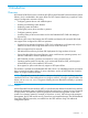
Why UEFI over Legacy BIOS? ProLiant DL580 Gen8 servers transition to UEFI as the limitations of Legacy BIOS prevent the adoption of new technologies. Table 1 (page 8) provides details of how UEFI provides more functionality than Legacy BIOS. Table 1 UEFI versus Legacy BIOS Functionality Description BIOS limitation BIOS cannot boot from hard disks with more than 2.1 TB. Pre-boot security UEFI provides an enhanced networking API that enables network authentication in a pre-boot environment.
Table 3 Comparison of UEFI versus Legacy BIOS (continued) Characteristic UEFI Legacy BIOS The ACPI spec is maintained by the Legacy BIOS-based systems is an UEFI forum, ensuring that OEM responsibility. UEFI-compliant systems are ACPI-compliant. Video support Pre-boot video functions available using Graphics Output Protocol (GOP). Video renders in full graphics mode. Pre-boot video displays in text mode only. Requires INT10h and video BIOS after boot.
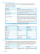
3. To navigate through and modify settings in the menu-driven interface, use the keys defined in the following table. Key Action Up or down arrow Press to change a selection. Enter Press to select an entry. ESC Press to go back to the previous screen. F1 Press to view online help about a selected option. F7 Press to load default RBSU configuration settings. You need to reboot the system for changes to take effect. Press Enter to apply defaults. Press ESC if you want to cancel.
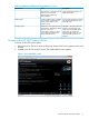
2 Getting Started: Overview of the System Utilities Figure 2 (page 11) shows the System Utilities screen, the main screen in the UEFI System Utilities menu-driven interface. The following functions can be accessed from the System Utiities screen: • System configuration • One-Time Boot menu • System information • Other submenu options To access System Utilities menu: 1. Reboot the server and press F9 when prompted during the startup sequence.
2. Use the keyboard up or down arrows to select an option, and then press Enter to display the submenu for that option. NOTE: You might also see options for your system devices, such as an embedded NIC. For example, “Embedded FlexibleLOM Port 1.” These items reflect installed PCIe cards. These devices vary based on the particular system. Configure the parameters for these devices as needed.
3 Accessing the System Configuration Menu The System Configuration menu options control a wide variety of server configurations. Figure 3 (page 13) shows the System Configuration portion of the UEFI System Utilities. NOTE: You might also see options for your system devices such as embedded NIC. For example, “Embedded FlexibleLOM Port 1.” These devices vary based on the particular system. Configure the parameters for these devices as needed by selecting the device and pressing Enter.
1. From the System Utilities screen, select System Configuration→BIOS/Platform Configuration. The BIOS/Platform Configuration (RBSU) screen appears. Figure 4 BIOS/Platform Configuration screen 2. Select an option, and then press Enter.
1. From the System Utilities screen, select System Configuration→BIOS/Platform Configuration→System Options. The System Options screen appears. Figure 5 System Options screen 2. Select one of the following options and press Enter. • Serial Port Options—Assigns COM port number and associated resources to the selected physical serial port. Also, lets you assign the logical COM port address and associated default resources for the Virtual Serial Port (VSP).
Setting the Embedded Serial Port You can assign a logical COM port address and associated default resources to the selected physical serial port. The operating system can overwrite this setting. 1. From the System Utilities screen, select System Configuration→BIOS/Platform Configuration (RBSU)→System Options→Serial Port Options→Embedded Serial Port and press Enter. 2. Select one of the following options: 3.
Figure 7 Serial Port Options — Virtual Serial Port screen Accessing Network Boot Options You can configure network boot settings, such as enabling or disabling network boot for Embedded NICs or setting the PXE boot policy. To access Network Boot Options: 1. From the System Utilities screen, select System Configuration→BIOS/Platform Configuration (RBSU)→System Options→Network Boot Options.
2. Select one of the following options: • “Selecting a UEFI PXE Boot Policy” (page 18) • “Setting Network Boot Retry Support” (page 19) Figure 8 Network Boot Options screen Selecting a UEFI PXE Boot Policy You can select the UEFI PXE (Pre-Boot Execution Environment) network boot policy. If both IPv4 and IPv6 are enabled, each network boot target appears twice in the UEFI boot order list (one for IPv4 and the other for IPv6). You can only configure this option when Boot Mode is set to UEFI.
Figure 9 Network Boot Options —UEFI PXE Boot Policy screen Setting Network Boot Retry Support You can set the network boot retry setting. By default, the system BIOS attempts to boot the network device (for example, PXE device) up to 20 times before attempting to boot the next IPL device. To set Network Boot Retry support: 1. From the System Utilities screen, select System Configuration→BIOS/Platform Configuration (RBSU)→System Options→Network Boot Options →Network Boot Retry Support and press Enter. 2.
Figure 10 Network Boot Options — Network Boot Retry Support screen Accessing USB Options This menu lets you set USB control, USB boot support, and removable flash media boot sequence. To access USB options: 1. From the System Utilities screen, select System Configuration→BIOS/Platform Configuration (RBSU)→System Options→USB Options. 2.
Figure 11 Network Boot Options —USB Control screen Setting USB Boot Support Use this option to prevent the system from booting any USB devices connected to the server and to disable booting the iLO virtual media. To set USB boot support: 1. From the System Utilities screen, select System Configuration→BIOS/Platform Configuration (RBSU)→System Options→USB Options→USB Boot Support and press Enter. 2. Select one of the following options: 3.
Figure 12 USB Options — USB Boot Support screen Setting Removable Flash Media Boot Sequence Select which USB or SD Card devices you want to search first when enumerating boot devices. Select whether the system should attempt to boot external USB drive keys, internal USB drive keys, or the internal SD Card slot first. This option does not override the device boot order in the Standard Boot Order (IPL) option. Configure this option only when Boot Mode is set to Legacy BIOS.
Figure 13 Options — Removable Flash Media Boot Sequence screen Configuring Processor Options You can configure processor options, such as protecting a system from viruses, enabling virtualization technology, disabling Intel Hyperthreading, enabling processor cores, and enabling Intel Virtualization Technology. To access processor options: • From the System Utilities screen, select System Configuration→BIOS/Platform Configuration (RBSU)→System Options→Processor Options.
3. Press F10 to save your selection. NOTE: Ensure this option is enabled if using Virtual Machine Manager, such as VMware ESX/ESXi and Windows Hyper-V. Figure 14 Processor Options — No-Execute Protection screen Enabling Virtualization Technology You can configure a Virtual Machine Manager that supports this option to use hardware capabilities provided by Intel’s virtualization technology. To enable virtualization technology: 1.
Figure 15 Processor Options — Virtualization Technology screen Disabling Intel Hyper-Threading You can disable the logical processor cores on processors supporting Intel’s Hyper-Threading Technology. This option improves overall performance for applications that benefit from a higher processor core count. The option is supported through the system BIOS. NOTE: Hyper-Threading is not supported on all processors. For more information, see the documentation for your processor model.
Figure 16 Processor Options — Intel Hyper-Threading Options screen Disabling Processor Cores You can disable processor cores that use Intel Core Multi-Processing (CMP) Technology. This option can reduce processor power usage and improve performance with some applications. It can improve overall performance for applications that benefit from higher performance cores rather than more processing cores. This option can also address issues with software that is licensed on a per-core basis.
Figure 17 Processor Options — Processor Core Disable screen Setting Intel Turbo Boost Technology Turbo Boost Technology lets the processor transition to a higher frequency than the processor's rated speed if the processor has available power and is within temperature specifications. To set Intel Turbo Boost technology: 1. From the System Utilities screen, select System Configuration→BIOS/Platform Configuration (RBSU)→System Options→Processor Options→Intel Hyperthreading Options and press Enter. 2.
Figure 18 Intel Turbo Boost Technology screen Enabling Intel VT-d You can enable a Virtual Machine Manager (VM Manager must support this feature) to use hardware capabilities provided by the Intel Virtualization Technology for Directed I/O. To enable Intel VT-d: 1. From the System Utilities screen, select System Configuration→BIOS/Platform Configuration (RBSU)→System Options→Processor Options→Intel VT-d and press Enter. 2. Select one of the following options: 3.
Figure 19 Processor Options — Intel VT-d screen Accessing UEFI Shell Options You can enable the UEFI Shell, add the Embedded UEFI Shell in the boot order, and enable automatic execution of the default startup script for the Embedded UEFI Shell. To access UEFI Shell options: 1. From the System Utilities screen, select System Configuration→BIOS/Platform Configuration (RBSU)→System Options→UEFI Shell Options. 2.
Figure 20 UEFI Shell Options screen Enabling the Embedded UEFI Shell You can enable or disable the Embedded UEFI Shell. The UEFI Shell is a pre-boot command line environment for scripting and running UEFI applications, including UEFI boot loaders. The UEFI Shell also provides CLI-based commands to obtain system information and configure and update the system BIOS. Enabling this option adds the Embedded UEFI Shell to the UEFI boot options. You can only configure this option if Boot Mode is set to UEFI.
Figure 21 UEFI Shell Options — Embedded UEFI Shell screen Adding Embedded UEFI Shell to the boot order list Adding the Embedded UEFI Shell as an entry in the Boot Order list is only applicable when the Embedded UEFI Shell is enabled and Boot Mode is set as UEFI. Otherwise, this option is grayed out. NOTE: When enabling this option, the Embedded UEFI Shell does not appear in the UEFI Boot Order list until the next system reboot. To add the Embedded UEFI Shell to the boot order list: 1.
Figure 22 UEFI Shell Options — Add Embedded UEFI Shell to the Boot Order screen Enabling the UEFI Shell Script Auto Start You can enable or disable automatic execution of the default UEFI Shell startup script during shell startup. When enabled, the shell looks for the startup.nsh file in any of the FAT16 or FAT32 file systems available. If you do not have the startup.nsh file, name the script file “startup.nsh” and place it in a UEFI accessible file system on a fixed or removable media.
Figure 23 Shell Options — UEFI Shell Script Auto Start screen Configuring Advanced Memory Protection You can configure additional memory protection with ECC (error checking and correcting). Advanced ECC provides the largest memory capacity to the operating system. To configure advanced memory protection: 1. From the System Utilities screen, select System Configuration→BIOS/Platform Configuration (RBSU)→System Options→Advanced Memory Protection and press Enter. 2.
Figure 24 Advanced Memory Protection screen Accessing Boot Options You can change the order of the UEFI boot order list, change the order of Legacy boot settings, select a boot mode, and set the UEFI optimized boot mode. NOTE: The server needs to be rebooted when changes are made to the boot mode To access the boot options: 1. From the System Utilities screen, select System Configuration→BIOS/Platform Configuration (RBSU)→Boot Options and press Enter. 2. Select an option, and then press Enter.
Figure 25 Boot Options screen Changing the UEFI boot order list To change the order of the UEFI boot list: 1. From the System Utilities screen, select System Configuration→BIOS/Platform Configuration (RBSU)→Boot Options→UEFI Boot Order and press Enter. The UEFI Boot Order screen appears. 2. Select Enter to open the Boot Order list. 3. Use the arrow keys to navigate within the boot order list. 4. Press the + key (plus) to move an entry higher in the boot list. 5.
Figure 26 Boot Options — UEFI Boot Order screen Accessing Advanced UEFI Boot Maintenance options Advanced UEFI boot maintenance options let you add an OS boot loader or application file that is located on removable media either attached to the server or virtual media from the iLO console. To access advanced UEFI boot maintenance options: 1. From the System Utilities screen, select System Configuration→Advanced UEFI Boot Maintenance and press Enter. 2.
Figure 27 Advanced Boot Maintenance screen Adding a Boot Option You can browse all FAT16 and FAT32 file systems. You can then select an X64 UEFI application with an .EFI extension to add as a new UEFI boot option (such as an OS boot loader or other UEFI application). The new boot option is appended to the boot order list. Once you select a file, you are prompted to enter the boot option description (which is then displayed in the Boot menu), as well as any optional data to be passed to an .EFI application.
Figure 28 Add Boot Option screen Figure 29 Modify Boot Option Description screen 38 Accessing the System Configuration Menu
Figure 30 UEFI Boot Order — Example Deleting a Boot Option You can delete a UEFI boot option from the boot order list. If the options points to a standard boot location (such as Network PXE boot or a removable media device), the system BIOS adds the option on the next system reboot. To delete boot options: 1. From the System Utilities screen, select System Configuration→Advanced UEFI Boot Maintenance→Delete Boot Option and press Enter. 2. Select a port from the list. 3.
Figure 31 Delete Boot Option screen Setting the Legacy Boot Mode order If your server is configured in Legacy mode, you can change the order for Legacy Boot Mode settings. This settings defines how the server looks for OS boot firmware. To change Legacy boot settings: 1. From the System Utilities screen, select System Configuration→BIOS/Platform Configuration (RBSU)→Boot Options→Legacy BIOS Boot Order and press Enter. The Legacy Boot Order screen appears. 2.
Figure 32 Legacy Boot Order screen Selecting a Boot Mode You can select the boot mode for the system to be either UEFI or Legacy BIOS. To select a boot mode: 1. From the System Utilities screen, select System Configuration→BIOS/Platform Configuration (RBSU)→Boot Options→Boot Mode and press Enter. The Boot Mode screen appears. 2. Select one of the following options: 3. 4. 5. • UEFI Mode—Configures the system to boot to a UEFI compatible operating system.
Figure 33 Boot Mode screen Setting UEFI Optimized Boot Configure the system to use native UEFI graphic drivers when booting to the UEFI Boot Mode. This option needs to be enabled to configure Secure Boot. For more information, see “Configuring Secure Boot” (page 69) for more information. Set the Boot Mode to UEFI before you can configure this option. See “Selecting a Boot Mode” (page 41) for detailed information.
Figure 34 UEFI Optimized Boot screen Setting the Boot Order Policy You can control the platform behavior when booting through the boot order. To set the Boot Order Policy: 1. From the System Utilities screen, select System Configuration→BIOS/Platform Configuration (RBSU)→Boot Options→Boot Order Policy and press Enter. The Boot Order Policy screen appears. 2. Select one of the following options: 3. 4.
Figure 35 Boot Options — Boot Order Policy screen Accessing Power Management This menu lets you enable such features as channel interleaving and collaborative power control. You can also set the QPI link frequency to a lower speed and set the processor idle power state. To access power management options: 1. From the System Utilities screen, select System Configuration→BIOS/Platform Configuration (RBSU)→Power Management and press Enter. The Power Management screen appears. 2.
Figure 36 Power Management — HP Power Profile screen Setting HP Power Regulator Configure the Power Regulator for ProLiant support. Configure this option only when the HP Power Profile is set to Custom. For more information, see “Setting HP Power Profile” (page 44). To set the HP Power Regulator: 1. From the System Utilities screen, select System Configuration→BIOS/Platform Configuration (RBSU)→Power Management→HP Power Regulator and press Enter. The Power Management screen appears. 2.
Figure 37 Power Management — HP Power Regulator screen Configuring Advanced Power Management Options To configure advanced power options: 1. From the System Utilities screen, select System Configuration→BIOS/Platform Configuration (RBSU)→Power Management→Advanced Power Management Options and press Enter. The Power Management screen appears. 2.
Place the Quick Path Interconnect links into a low power state when the links are not being utilized. This lowers power usage with minimal performance effect. You can only configure this feature if two or more CPUs are present. To configure Intel QPI Link Power Management: 1. From the System Utilities screen, select System Configuration→BIOS/Platform Configuration (RBSU)→Power Management→Advanced Power Options→Intel QPI Link Power Management and press Enter. 2. Select one of the following options: 3.
Figure 39 Intel QPI Link Frequency screen Setting QPI Bandwidth Optimization (RTID) NOTE: This option is available on Gen8 with Intel processors. The QPI link between two processors provides the best performance for most applications. To set QPI Bandwidth Optimization: 1. From the System Utilities screen, select System Configuration→BIOS/Platform Configuration (RBSU)→Power Management→Advanced Power Options→QPI Bandwidth Optimization (RTID) and press Enter. 2. Select one of the following options: 3.
Figure 40 QPI Bandwidth Optimization screen Setting Minimum Processor Idle Power Core State Select the lowest processor idle power state (C-state) that the operating system uses. The higher the C-state, the lower the power usage of the idle power state. C6 is the lowest power idle state supported by the processor. Configure this option only when HP Power Profile is set to “Custom.” To set minimum processor idle power core state: 1.
Figure 41 Advanced Power Management — Minimum Processor Idle Power Core State screen Setting Minimum Processor Idle Power Package State NOTE: This option is available on servers with Intel processors. Configure the lowest processor idle power state (C-state). The processor automatically transitions into package C-states based on the Core C-states in which cores on the processor have transitioned. The higher the package C-state, the lower the power usage of that idle package state.
Figure 42 Advanced Power Management — Minimum Processor Idle Power Package State screen Setting Energy/Performance Bias Configure several processor subsystems to optimize the processor’s performance and power usage. Configure this option only if the HP Power Profile is set to “Custom.” To set energy/performance bias: 1. From the System Utilities screen, select System Configuration→BIOS/Platform Configuration (RBSU)→Power Management→Advanced Power Options→Energy/Performance Bias and press Enter. 2.
Figure 43 Advanced Power Management — Energy/Performance Bias screen Setting Maximum Memory Bus Frequency Configure the system to run memory at a lower maximum speed than that supported by the installed processor and DIMM configuration. Setting this option to Auto configures the system to run memory at the maximum speed supported by the system configuration. Configure this option only when HP Power Profile is set to Custom. To set the maximum memory bus frequency: 1.
2. 3. Select one of the following options: • Enabled (default) • Disabled Press F10 to save your selection. Setting Maximum PCI Express Speed If a PCI-Express device does not run properly at its maximum speed, reducing the speed can address this issue. This option lets you lower the maximum PCI-express speed in which the server allows PCI-express devices to operate. It can be useful in addressing issues with problematic PCI-express devices.
for Dynamic Power Savings Mode, this option has no impact to system operation. Configure this option only if the HP Power Profile is set to Custom. To set the Collaborative Power Control: 1. From the System Utilities screen, select System Configuration→BIOS/Platform Configuration (RBSU)→Power Management→Advanced Power Options→Collaborative Power Control and press Enter. 2. Select one of the following options: 3. • Enabled (default) • Disabled Press F10 to save your selection.
Setting ACPI SLIT Preferences The ACPI SLIT (System Locality Information Table) describes the relative access times between processors, memory subsystems, and I/O subsystems. Operating systems that support the SLIT can use this information to improve performance by allocating resources and workloads more efficiently. To set ACPI SLIT Preferences: 1.
Figure 46 PCI Device Enable/Disable screen Setting the System Date and Time Set the system time and date on the server. To set the system date and time on the server: 1. From the System Utilities screen, select System Configuration→BIOS/Platform Configuration (RBSU)→Date and Time and press Enter. The Date and Time screen appears. 2. Select a device on your system from the list and press Enter. 3. Select Date (mm-dd-yyyy) and press Enter to set the date.
Figure 47 Date and Time screen Accessing the Server Availability menu Enable the automatic server recovery status and timeout, set thermal shutdown, configure power-on-self-test, set the power button mode, and set the power-on delay. To access the Server Availability menu: 1. From the System Utilities screen, select System Configuration→BIOS/Platform Configuration (RBSU)→Server Availability and press Enter. The Server Availability screen appears. 2.
Figure 48 Server Availability — ASR Status screen Setting ASR (Automatic Server Recovery) Timeout If Automatic Server Recovery is enabled, this option lets you set the time to wait before rebooting the server in the event of an operating system crash or server lockup. When the server has not responded in the selected amount of time, the server automatically reboots. To set ASR timeout: 1.
Figure 49 Server Availability — ASR Timeout screen Setting Thermal Shutdown Initiate a shutdown due to non-redundant fan failures or temperature increases beyond the pre-set threshold. If disabled, the System Management Driver ignores thermal events and the system immediately powers off in data-destructive situations. To set thermal shutdown: 1. From the System Utilities screen, select System Configuration→BIOS/Platform Configuration (RBSU)→Server Availability and select Thermal Shutdown and press Enter.
Figure 50 Server Availability — Thermal Shutdown screen Remotely Powering On the Server Configure the server to power on remotely when it receives a special packet. If you enable the Wake-On LAN option, the system can be powered up remotely using a WOL-capable NIC. This option requires a NIC, NIC driver, and operating system that are WOL-capable. If you choose the enabled option, the following caution appears: When enabling Wake-on LAN, remove all power cords before adding or removing any adapters.
Figure 51 Server Availability — Wake On LAN screen Configuring the POST (Power-On-Self-Test) F1 Prompt Configure the system to display the F1 key in the server POST screen. If an error is encountered, press the F1 key to continue with the server power-up sequence. To configure the POST F1 prompt: 1. From the System Utilities screen, select System Configuration→BIOS/Platform Configuration (RBSU)→Server Availability and select POST F1 Prompt and press Enter. 2. The following options are available: 3. 4.
Figure 52 Server Availability — POST F1 Prompt screen Setting Power Button Mode Disabling this option disables the momentary power button functionality. This option does not effect the four-second power button override or the remote power control functionality. To set power button mode: 1. From the System Utilities screen, select System Configuration→BIOS/Platform Configuration (RBSU)→Server Availability and select Power Button Mode and press Enter. 2. Select one of the following options: 3.
Figure 53 Server Availability — Power Button Mode screen Setting Automatic Power-On Configure the server to automatically power on when AC power is applied to the system. By default, the system returns to its previous power state when AC power is restored after an AC power loss. This option allows overriding this behavior such that the system always returns to the "on" state whenever power is applied (even if the system had been in the off state when power was lost).
Figure 54 Server Availability — Automatic Power-On screen Setting Power-On Delay Delay the server from turning on for the desired time. Pressing the power button (using the iLO Virtual Power Button) Wake-ON LAN events and RTC (Real-Time Clock) wake-up events overrides the delay and immediately turns on the server. This allows staggering when servers power-up after a power loss to prevent power usage spikes. To set Power-On Delay: 1.
Figure 55 Server Availability — Power-On Delay Accessing the Server Security menu Control access to the server and its utilities. This menu sets the power-on and administrator passwords, set Intelligent Provisioning, and access the Trusted Platform Module. To access the Server Security menu: 1. From the System Utilities screen, select System Configuration→BIOS/Platform Configuration (RBSU)→Server Security and press Enter. 2.
Figure 56 Server Security screen Setting a Power On Password Set a password for accessing the server during the boot process. When powering-on the server, a prompt appears where you enter the password to continue. To disable or clear the password, enter the password followed by a / (slash) when prompted to enter the password. NOTE: In the event of an Automatic Server Recovery (ASR) reboot, the power-on password is bypassed and the server boots normally. To set a power-on password: 1.
Figure 57 Server Security — Set Power On Password screen Setting an Administrator Password Set an administrator password to protect the server configuration. If enabled, you are prompted for this password before being allowed to modify the configuration. To set the administrator password: 1. From the System Utilities screen, select System Configuration→BIOS/Platform Configuration (RBSU)→Server Security and select Set Admin Password and press Enter. 2. Enter the password and press Enter. 3.
Figure 58 Server Security — Set Admin Password screen Disabling the F11 One-Time Boot Menu This menu specifies a specific boot override option for this boot only. This option does not modify the normal boot order settings. By default, you can boot directly into the One-Time Boot menu in the System Utilities by pressing F11 in the HP ProLiant main screen after a server reboot. See “Configuring a One-Time Boot Menu” (page 139) for more details about options in the One-Time Boot menu.
Figure 59 Server Security — F11 Boot Menu Prompt Disabling Intelligent Provisioning (F10 Prompt) This option disables the Intelligent Provisioning functionality. If this option is disabled, you are prevented from entering the Intelligent Provisioning environment by pressing F10 during server boot. Set this option to “Enabled” use the Intelligent Provisioning functionality. To disable Intelligent Provisioning (F10 Prompt): 1.
HP UEFI System Utilities and Shell Release Notes on the HP website (http://www.hp.com/go/ ProLiantUEFI/docs). A physically present user can customize the certificates embedded in the UEFI BIOS by adding/removing their own certificates. Before configuring Secure Boot, select the UEFI Boot Mode. See “Selecting a Boot Mode” (page 41). Also enable the UEFI Optimized Boot option. See “Setting UEFI Optimized Boot” (page 42) for details. To configure Secure Boot: 1.
Setting the Secure Boot Custom Mode If you select the “Custom Mode” for Secure Boot mode, the Secure Boot Custom Mode Options menu appears. From this menu, select the Platform Key (PK) Options, Key Exchange Key (KEK) Options, Allowed Signatures Database (DB) Options, and Forbidden Signatures Database (DBX) Options. Figure 61 Server Security — Secure Boot Custom Mode Options screen 1. 2. Select Secure Boot Mode Options and press Enter. Select one of the following options:.
Figure 62 Server Security — Custom Secure Boot Options screen Enrolling a Platform Key (PK) A Platform Key protects the next key from uncontrolled modification. Select this option to enter the Platform Key (PK) options menu. You can enroll or delete the PK certificate. The file must be in DER-encoded certificate format. To enroll a Platform Key: 1. Select Platform Key (PK) Options→Enroll PK and press Enter. 2. Select Enroll PK using File and press Enter.
Figure 63 Server Security—Enroll PK screen Deleting a Platform Key You can delete a Platform Key. This requires an immediate system reboot. Deleting the PK forces Secure Boot to be disabled until you enroll a new PK. To delete a Platform Key: 1. Select Platform Key (PK) Options→Delete Platform Key (PK) and press Enter 2. Select a key from the list. 3. Press Enter (Yes) in the message prompt to delete the Key or ESC to cancel.
Figure 64 Server Security—Enroll KEK Entry screen Figure 65 Server Security—Enroll KEK using File screen Enrolling a Key or Signature using a Signature GUID You can optionally enroll a Key or Signature using a GUID. To enroll a Key or Signature using a Signature GUID: 1. Select Key Exchange Key (KEK) Options→Signature GUID (optional) and press Enter.
2. 3. Enter the optional security certificate Signature GUID and press Enter. Enter the data in the following GUID format (36 characters): 11111111-2222-3333-4444-1234567890ab. • For Hewlett Packard certificates, enter F5A96B31-DBA0-4faa-A42A-7A0C9832768E • For Microsoft certificates, enter 77fa9abd-0359-4d32-bd60-28f4e78f784b • For SUSE certificates, enter 2879c886-57ee-45cc-b126-f92f24f906b9 Select Commit changes and exit to save your changes.
Figure 67 Server Security—Enroll DB Signature using File screen Forbidden Signatures Database (DBX) Options The database maintains signatures of codes that are forbidden to run on the platform. Select this option to enter the Forbidden Signatures (DBX) Options menu. You can enroll or delete the DBX signatures. To enroll a Forbidden Signature Database (DBX): 1. Select Forbidden Signatures Database (DB) Options→Enroll Signature and press Enter. 2. Select Enroll Signature using File and press Enter. 3.
Figure 68 Server Security—Enroll DBX Signature screen Figure 69 Server Security—Enroll DBX Signature using File screen Accessing the Trusted Platform Module (TPM) Trusted Platform Module (TPM) allows the firmware and operating system to take measurements of all phases of the booting process.
1. 2. From the System Utilities screen, select System Configuration→BIOS/Platform Configuration (RBSU)→Server Security and select Trusted Platform Module Options and press Enter. For servers configured with an optional TPM, the following configuration option is available: • “Setting TPM Functionality” (page 78) IMPORTANT: TPM menus appear only if the TPM kit is installed. Setting TPM Functionality This option controls Trusted Platform Module functionality at startup.
Figure 70 BIOS Serial Console and EMS screen Setting BIOS Serial Console Port You can re-direct video and keystrokes through the serial port to OS boot. This option can interfere with non-terminal devices attached to the serial port. In this case, set this option to “Disabled.” IMPORTANT: This option is not supported under RBSU on Japanese or Simplified Chinese systems. To set the BIOS serial console port: 1.
Figure 71 BIOS Serial Console and EMS — BIOS Serial Console Port screen Setting BIOS Serial Console Emulation Mode You can select an emulation mode type. The selected option depends on the emulation you want to use in your serial terminal program (for example, HyperTerminal or PuTTY). The BIOS emulation mode must match the selected mode in the terminal program. To set the BIOS Serial Console Emulation Mode: 1.
Figure 72 BIOS Serial Console and EMS — BIOS Serial Console Emulation Mode screen Setting BIOS Serial Console Baud Rate You can set the transfer rate at which data is transmitted through the serial port. To set the BIOS Serial Console Emulation Port: 1. From the System Utilities screen, select System Configuration→BIOS/Platform Configuration (RBSU)→BIOS Serial Console and EMS and select BIOS Serial Console Baud Rate and press Enter. 2. Select one of the following baud rates: 3.
Figure 73 BIOS Serial Console and EMS — BIOS Serial Console Baud Rate screen Setting the EMS Console You can configure the ACPI serial port settings, which can be used to configure the Windows Server Emergency Management (EMS) console to be redirected through a serial port.
Figure 74 BIOS Serial Console and EMS — EMS Console screen EMS provides input/output support for all Microsoft Windows kernel components: the loader, setup, recovery console, OS kernel, blue screens, and the Special Administration Console. The Special Administration Console is a text mode management console available after Windows Server 2008 or 2012 OS has initialized. Microsoft enables EMS in the OS, but EMS must also be enabled in the ROM.
Figure 75 Server Asset Text menu screen Entering Server Info Text menu These options define reference information for the server administrator. To enter server information text: 1. From the System Utilities screen, select System Configuration→BIOS/Platform Configuration (RBSU)→Server Asset Text and select Server Info Text and press Enter. 2. Select one of the following options: 3. 84 • Server Name—Identifies the server. • Server Asset Tag—Identifies the server asset number.
Figure 76 Server Asset Text — Server Info Text screen NOTE: Each of these options can display a maximum of 14 characters. By default, all values are blank. Entering Administrator Information You can define contact information for the server administrator. To enter administrator information: 1. From the System Utilities screen, select System Configuration→BIOS/Platform Configuration (RBSU)→Server Asset Text and select Administrator Information and press Enter. 2.
Figure 77 Server Asset Text — Administrator Information screen NOTE: The number of characters allowed for each entry varies depending on server model. By default, all values are blank. Entering Service Contact Text You can define reference information for the server administrator. To enter service contact text: 1. From the System Utilities screen, select System Configuration→BIOS/Platform Configuration (RBSU)→Server Asset Text and select Service Contact Information and press Enter. 2.
Figure 78 Server Asset Text — Service Contact Information screen Entering a Custom POST Message You can enter a custom message to display during server POST in the HP ProLiant POST screen. To enter a custom POST message: 1. From the System Utilities screen, select System Configuration→BIOS/Platform Configuration (RBSU)→Server Asset Text and select Custom POST Message and press Enter. 2. Enter a custom POST message as needed. A maximum of 60 characters is supported. By default, this value is blank. 3.
Figure 79 Server Asset Text — Custom POST Message screen Accessing Advanced Options You can display advanced system ROM options, advanced performance tuning options, enable the embedded video controller for iLO remote video and dual-head video support to functions properly, override the system power supply requirements, select the fan cooling system, and lock asset tag information. To access the Advanced Options menu 1.
Figure 80 Advanced Options screen Accessing Advanced System ROM Options This menu lets you enter a chassis serial number and product ID, set ROM selection, NMI debug button, virtual install disk, PCI bus padding, and power-on logo, and consistent device naming. You can also enable SR-IOV support. To access advanced system ROM options: 1. From the System Utilities screen, select System Configuration→BIOS/Platform Configuration (RBSU)→Advanced Options→Advanced System ROM Options and press Enter. 2.
Figure 81 Advanced Options — Advanced System ROM options screen Entering a Chassis Serial Number After replacing the system board, re-enter the server serial number. Consult a qualified IT service specialist for assistance in modifying this value. To enter a chassis serial number: 1. From the System Utilities screen, select System Configuration→BIOS/Platform Configuration (RBSU)→Advanced Options→Advanced System ROM Options→Serial Number and press Enter. 2. Enter the serial number and press Enter. 3.
2. 3. The following configuration options are available: • Use Current ROM (default) • Switch to Backup ROM Press F10 to save your selection. Figure 82 Advanced Options — ROM Selection screen Setting NMI Debug Button You can enable debug functionality when the system has experienced a software lock-up. The NMI Debug Button generates an NMI to enable the use of the operating system debugger.
Figure 83 Advanced Options —NMI Debug Option screen Setting Virtual Install Disk You can control the Virtual Install Disk. The Virtual Install Disk can contain drivers specific to the server that an operating system can use during installation. If this option is enabled, Microsoft Windows Server automatically locates required drivers and installs them, eliminating the need for user intervention and the requirement that a driver be present on external media during operating system installation.
Figure 84 Advanced Options —Virtual Install Disk screen Setting PCI Bus Padding Options You can disable the default PCI Bus padding where each expansion slot is provided with an extra PCI Bus number. By default, the System BIOS pads one PCI bus per expansion slot to allow expansion cards with PCI-PCI bridges to not effect current bus numbering schemes. Disabling this option works around issues with certain expansion cards. It is not recommended to disable this option unless a specific issue is encountered.
Figure 85 Advanced Options — PCI Bus Padding Options Setting Power-On Logo This option controls the display of the logo during system boot. This is an aesthetic modification only and does not affect the system boot times. To set power-on logo: 1. From the System Utilities screen, select System Configuration→BIOS/Platform Configuration (RBSU)→Advanced Options→Advanced System ROM Options→Power-On Logo and press Enter. 2. Select one of the following options: 3.
Figure 86 Advanced Options — Power-On Logo screen Enabling SR-IOV Support You can create virtual instances of a PCI device for use under a Hypervisor-based operating system. When you create virtual instances, the BIOS allocates more PCI resources to the PCI devices. Enable this option for a PCIe device or operating system that supports SR-IOV. To enable SR-IOV support: 1.
Figure 87 Advanced Options — SR-IOV screen Setting Consistent Device Naming You can select the level of Consistent Device Naming. On supported operating systems, NIC ports are named based on their location in the system. To set device naming: 1. From the System Utilities screen, select System Configuration→BIOS/Platform Configuration (RBSU)→Advanced Options→Advanced System ROM Options→Consistent Device Naming and press Enter. 2. Select one of the following options: 3.
Figure 88 Advanced Options — Consistent Device Naming screen Setting PCI Express 64-Bit BAR Support Force PCIe resources to use 32–bit MMIO addressing. Disabling 64–bit BAR support might be necessary for certain legacy option card device to function properly when Boot Mode is set to “Legacy Boot.” To set PCI express 64-bit BAR support: 1.
Figure 89 PCI Express 64–Bit BAR Support screen Setting Processor X2Apic Support This option enables support for processor X2Apic devices. Enabling this option generates ACPI X2Apic structures. To set processor X2Apic support: 1. From the System Utilities screen, select System Configuration→BIOS/Platform Configuration (RBSU)→Advanced Options→Advanced System ROM Options→Processor X2Apic Support and press Enter. 2. Select one of the following options: 3.
Figure 90 Processor X2Apic Support Setting ACPI RASF Table Support This option enables the ACPI RASF table. Enabling this option generates the ACPI RASF table. To set ACPI RASF Table Support: 1. From the System Utilities screen, select System Configuration→BIOS/Platform Configuration (RBSU)→Advanced Options→Advanced System ROM Options→ACPI RASF Table Support and press Enter. 2. Select one of the following options: 3. • Enabled (default) • Disabled Press F10 to save your selection.
Figure 91 ACPI RASF Table Support screen Setting ACPI Root Bridge PXM Preferences This option enables Root Bridge devices PXM objects. Enabling this option generates an ACPI PXM method for PCI Root Bridge devices. To set ACPI Root Bridge PXM Preferences: 1. From the System Utilities screen, select System Configuration→BIOS/Platform Configuration (RBSU)→Advanced Options→Advanced System ROM Options→ACPI Root Bridge PXM Preferences and press Enter. 2. Select one of the following options: 3.
Figure 92 ACPI Root Bridge PXM Preferences screen Configuring Extended Memory Test You can configure the system to validate memory during the memory initialization process. If uncorrectable memory errors are detected, the memory is mapped out and failed DIMMs are logged to the Integrated Management Log (IML). Enabling this option can result in a significant increase in the system boot time. To configure extended memory test: 1.
Figure 93 Extended Memory Test screen ACPI RTC Support You can configure standard ACPI (Advanced Configuration and Power Interface) tables to determine whether the operating system should use RTC (Real-Time Clock) for date/time information. Typically, you should set this option to Disabled (default). Newer operating systems support ACPI tables to handle date/time information. Older operating systems do not support ACPI tables. To configure ACPI RTC Support: 1.
Figure 94 ACPI RTC Support screen Accessing Advanced Performance Tuning This menu lets you set HW prefetcher, adjacent sector prefetch, DCU stream prefetcher, DCU IP prefetcher, node interleaving, and performance counter monitor. It also lets you set HP SmartMemory. To access the Advanced Performance Tuning Options menu: 1. From the System Utilities screen, select System Configuration→BIOS/Platform Configuration (RBSU)→Advanced Options→Advanced Performance Tuning Options and press Enter. 2.
To set HW prefetcher: 1. From the System Utilities screen, select System Configuration→BIOS/Platform Configuration (RBSU)→Advanced Options→Advanced Performance Tuning Options→HW Prefetcher and press Enter. 2. Select one of the following options: 3. • Enabled • Disabled Press F10 to save your selection. Figure 95 Advanced Options — HW Prefetcher screen Setting Adjacent Sector Prefetch You can disable the processor prefetch option. In most cases, this option should remain enabled.
Figure 96 Advanced Options — Adjacent Sector Prefetch screen Setting DCU Stream Prefetcher You can control processor prefetching. In most cases, leave this option enabled. With certain workloads, however, disabling this option can provide a performance benefit. Disable this option only after performing application benchmarking to verify improved performance in a particular environment. To set DCU Stream Prefetcher: 1.
Figure 97 Advanced Options — DCU Stream Prefetcher screen Setting DCU IP Prefetcher You can control processor prefetching. In most cases, this option should remain enabled. With certain workloads, however, disabling this option can provide a performance benefit. Disable this option only after performing application benchmarking to verify improved performance in a particular environment. To set DCU IP prefetcher: 1.
Figure 98 Advanced Options — DCU IP Prefetcher screen Setting Node Interleaving You can disable the NUMA architecture properties of the system. All operating systems supported by this platform support NUMA architectures. In most cases, obtain optimum performance by disabling Node Interleaving. When this option is enabled, memory addresses are interleaved across the memory installed for each processor and some workloads might experience improved performance.
Figure 99 Advanced Options — Node Interleaving screen Setting 1333 MHz Support for 3DPC PC3-10600H HP SmartMemory NOTE: This option is available on Gen8 with 3DPC PC3-10600H HP SmartMemory. You can enable a memory speed of 1333 Mhz for 3-DIMM per channel configurations and should be enabled only when the system contains PC3-10600H HP Smart Memory exclusively. To set 3DPC PC3-10600H HP SmartMemory: 1.
Figure 100 Advanced Options — 1333 MHz Support for 3DPC-10600H HP SmartMemory screen Setting 1333 MHz Support for 3DPC PC3-12800R HP SmartMemory NOTE: This option is available on Gen8 with 3DPC PC3-12800R HP SmartMemory. You can enable memory speed of 1333 Mhz for 3DIMM per-channel configurations. This option should be enabled only when the system contains exclusively PC3-12800R HP Smart Memory. To set 1333 MHz Support for 3DPC PC3-12800R HP SmartMemory: 1.
Figure 101 Advanced Options — 1333 MHz Support for 3DPC PC3-12800R HP SmartMemory screen Enabling Intel NIC DMA Channels This a NIC acceleration option that only runs on Intel Based NICs. For servers that do not have an Intel NIC, leave this option disabled. To enable Intel NIC DMA channels: 1. From the System Utilities screen, select System Configuration→BIOS/Platform Configuration (RBSU)→Advanced Options→Advanced Performance Tuning Options→Intel NIC DMA Channels and press Enter. 2.
Figure 102 Advanced Options — Intel NIC DMA Channels screen Setting Intel Performance Counter Monitor (PCM) You can unhide certain performance counters in the processor. If enabled, you can use tools such as PCM. To set PCM: 1. From the System Utilities screen, select System Configuration→BIOS/Platform Configuration (RBSU)→Advanced Options→Advanced Performance Tuning Options→Intel Performance Counter Monitor (PCM) and press Enter. 2. Select one of the following options: 3.
Figure 103 Intel Performance Counter Monitor (PCM) screen Setting Video Options You can configure the video display. By default, the system BIOS disables the embedded video controller when an optional video controller is installed in the system. This option allows the embedded video controller to remain enabled so that the iLO remote video functions properly or for dual-head video support. Early system startup video is always displayed to the embedded video controller. To set video options: 1.
Figure 104 Advanced Options — Video Options screen Setting Power Supply Requirements Override The server can operate workloads and configurations with the required power supplies installed. You can modify the server's power supply requirements to allow the server to operate with one power supply and be redundant or with two power supplies and be redundant with three power supplies.
Figure 105 Advanced Options — Power Supply Requirements Override screen Setting Thermal Configuration You can select the fan cooling solution for the system. To set thermal configuration: 1. From the System Utilities screen, select System Configuration→BIOS/Platform Configuration (RBSU)→Advanced Options→Thermal Configuration and press Enter. 2.
Figure 106 Advanced Options — Thermal Configuration screen Locking Asset Tag Protection You can protect asset tag information. To lock the asset tag information: 1. From the System Utilities screen, select System Configuration→BIOS/Platform Configuration (RBSU)→Advanced Options→Asset Tag Protection and press Enter. 2.
Figure 107 Advanced Options — Asset Tag Protection screen Accessing System Default Options To access system default options: 1. From the System Utilities screen, select System Configuration→BIOS/Platform Configuration (RBSU)→System Default Options and press Enter.
2. The following configuration options are available: • Restore Default System Settings—Resets all configuration settings to their default values. Any changes you made are not saved. • Restore Default Manufacturing Settings— Resets all configuration settings to their default manufacturing values. Previous changes that you have made are lost. • User Default Options—Defines default configuration settings, which are used instead of the factory default settings.
Figure 109 System Default Options — Restore Default System Settings Restoring Default Manufacturing Settings Restoring default manufacturing settings lets you reset all BIOS configuration settings to their default manufacturing values and delete all UEFI non-volatile variables, such as boot configuration and Secure Boot security keys (if Secure Boot is enabled). Previous changes that you have made are lost. To restore default manufacturing settings: 1.
Figure 110 System Default Options — Restore Default Manufacturing Settings screen Saving Default Settings You can configure default settings as necessary and then save the configuration as the custom default configuration. When the system loads the default settings, the custom default settings are used instead of the manufacturing defaults. To save custom default settings: 1.
Figure 111 System Default Options — User Default Options screen 120 Accessing the System Configuration Menu
4 Accessing Smart Array Controllers You can access Smart Array Controllers and view device information. HP 12Gb/s capable SAS Smart Array controllers (for example, HP Smart Array P430, P431, P731m, and P830 Controllers) support UEFI-based servers. For more information, see the HP Smart Array Controllers compatibility matrix at www.hp.com/go/smartarray/gen8compat. To view information about Smart Array Controllers: 1.
Figure 113 Smart Array P830i Controller screen — Device Information 122 Accessing Smart Array Controllers
5 Using the iLO 4 Configuration Utility The iLO 4 Configuration Utility is available in the HP UEFI System Utilities. iLO 4 Configuration Utility has the following options: • Network Options • Advanced Network Options • User Management • Setting Options • About • Set to Factory Defaults For more information, see the HP iLO 4 User Guide. Accessing the iLO 4 Configuration Utility menu The iLO 4 Configuration Utility is embedded in the system ROM of HP ProLiant servers that support UEFI.
Figure 114 iLO 4 Configuration Utility screen 5. Select an option, and then press Enter.
Figure 115 Network Options screen 5. View or update the following values, as needed: • MAC Address (read-only)—The MAC address of the selected iLO network interface. • Network Interface Adapter—Specifies the iLO network interface adapter to use. Select ON to enable the iLO Dedicated Network Port. Select Shared Network Port to use the Shared Network Port. Selecting OFF disables all network interfaces to iLO. The Shared Network Port option is available only on supported servers.
• DNS Name—The DNS name of the iLO subsystem (for example, ilo instead of ilo.example.com). This name can be used only if DHCP and DNS are configured to connect to the iLO subsystem name instead of the IP address. 6. 7. 8. 9. • IP Address—The iLO IP address. If DHCP is used, the iLO IP address is supplied automatically. If DHCP is not used, enter a static IP address. • Subnet Mask—The subnet mask of the iLO IP network. If DHCP is used, the subnet mask is supplied automatically.
Figure 116 Advanced Network Options screen 5. 6. 7. 8. 9. View or update the following values, as needed: • Gateway from DHCP—Specifies whether iLO uses a DHCP server-supplied gateway. • Gateway #1, Gateway #2, and Gateway #3—If Gateway from DHCP is disabled, enter up to three iLO gateway IP addresses. • DHCP Routes—Specifies whether iLO uses the DHCP server-supplied static routes.
Managing iLO users by using the iLO 4 Configuration Utility You can use the iLO 4 Configuration Utility to perform the following user management tasks: • “Adding user accounts” (page 128) • “Editing or removing user accounts” (page 130) Adding user accounts You can use the iLO 4 Configuration Utility User Management menu to configure local iLO user accounts. To add local iLO user accounts: 1. Optional: If you access the server remotely, start an iLO remote console session. You can use the .
Figure 118 Configuring user account properties 6. 7. 8. 9. Select from the following iLO privileges. To enable a privilege, set it to YES. To disable a privilege, set it to NO. • Administer User Accounts—Enables a user to add, edit, and delete local iLO user accounts. A user with this privilege can change privileges for all users. If you do not have this privilege, you can view your own settings and change your own password.
10. Select Exit and Resume Boot in the main menu, and then press Enter. 11. When prompted to confirm the request, press Enter to exit the utility and resume the boot process. Editing or removing user accounts You can use the iLO 4 Configuration Utility User Management menu to edit or remove local iLO user accounts. To edit or remove a local iLO user account: 1. Optional: If you access the server remotely, start an iLO remote console session. You can use the .NET IRC or Java IRC. 2. 3.
Figure 120 Editing or removing user accounts 6. 7. 8. 9. 10. 11. 12. Locate the user name that you want to edit or delete, select the Action menu for that user name, and then press Enter. Select one of the following, and then press Enter. • No Change—Returns you to the main menu. • Delete—Deletes this user. • Edit—Edits the user. Depending on your selection in step 7, do one of the following: • If you selected No Change, no further action is needed.
4. From the System Utilities screen, select System Configuration→iLO 4 Configuration Utility→Setting Options. The Setting Options screen appears. Figure 121 Setting Options screen 5. View or update the following values, as needed: • iLO 4 Functionality—The iLO network and communications with operating system drivers are terminated when iLO functionality is disabled.
• • Serial CLI Status—This setting enables you to change the login model of the CLI feature through the serial port. The following settings are valid: ◦ Enabled-Authentication Required—Enables access to the iLO CLP from a terminal connected to the host serial port. Valid iLO user credentials are required. ◦ Enabled-No Authentication Required—Enables access to the iLO CLP from a terminal connected to the host serial port. iLO user credentials are not required.
Figure 122 About screen This screen includes the following information: 5. 6. 7. • Firmware Date—The iLO firmware revision date. • Firmware Version—The iLO firmware version. • iLO CPLD Version—The iLO complex programmable logic device version. • Host CPLD Version—The ProLiant server complex programmable logic device version. • Serial Number—The iLO serial number. • RBSU Date—The iLO 4 Configuration Utility revision date. • PCI BUS—The PCI bus to which the iLO processer is attached.
4. From the System Utilities screen, select System Configuration→iLO 4 Configuration Utility→Set to factory defaults. The iLO 4 Configuration Utility prompts you to select YES or NO. Figure 123 Set to factory defaults screen 5. Select YES, and then press Enter. The iLO 4 Configuration Utility prompts you to confirm the reset request.
The iLO system is reset, and you cannot access the iLO 4 Configuration Utility until after the next system reboot. You can press Enter to confirm, or press Esc to cancel. 6. Press Enter. iLO resets to the factory default settings. If you are managing iLO remotely, the remote console session is automatically ended. 7. Resume the boot process: a. Optional: If you are managing iLO remotely, wait for the iLO reset to finish, and then start the iLO remote console.
5. Select YES, and then press Enter. The iLO 4 Configuration Utility prompts you to confirm the reset request. When you reset iLO, the iLO 4 Configuration Utility is not available again until the next reboot. 6. Press Enter. iLO resets. If you are managing iLO remotely, the remote console session is automatically ended.
7. Resume the boot process: a. Optional: If you are managing iLO remotely, wait for the iLO reset to finish, and then start the iLO remote console. The UEFI System Utilities are still open from the previous session. b. c. d. 138 Press Esc until the main menu is displayed. Select Exit and Resume Boot in the main menu, and then press Enter. When prompted to confirm the request, press Enter to exit the utility and resume the normal boot process.
6 Configuring a One-Time Boot Menu You can select a UEFI boot option for a one-time boot override. This option does not modify your predefined boot order settings. To configure a One-Time boot menu: 1. From the System Utilities screen, select One-Time Boot Menu and press Enter. 2. Select one of the following options: 3. • Embedded UEFI Shell—Select this option to exit System Utilities and display the Embedded UEFI Shell prompt.
Mode” (page 41) for details. You also need to enable Embedded UEFI Shell from the UEFI Shell Options menu. See “Enabling the Embedded UEFI Shell” (page 30) for details. To access the Embedded UEFI Shell: 1. From the System Utilities screen, select One-Time Boot Menu and press Enter. 2. Select Embedded UEFI Shell and press Enter. You are taken to the Embedded UEFI Shell command screen. 3. Enter the exit command to exit the Shell. For information on running commands, see the HP UEFI Shell User Guide.
Figure 127 Shell Command Prompt Intelligent Provisioning (F10 Prompt) Intelligent Provisioning is an essential single-server deployment tool embedded in HP ProLiant Gen8 servers that simplifies HP ProLiant server setup, providing a reliable and consistent way to deploy HP ProLiant server configurations. This option lets you select the Intelligent Provisioning host override option for this boot only. This option does not modify the normal boot order or boot mode settings.
Figure 128 One-Time Boot Menu — Intelligent Provisioning screen 142 Configuring a One-Time Boot Menu
7 Viewing System Information The System Information menu lets you scan server details and check that the firmware version was updated after applying an update. To view system information: 1. From the System Utilities screen, select System Information and press Enter. 2.
8 Viewing Device Health Status You can check the health status of all devices in the system. For example, this screen could display the presence of an unsupported device found during the boot process. To check device health status: 1. From the System Utilities screen, select Device Health Status and press Enter. 2.
9 Selecting a Language You can select the current language for the system. Choose from English, Japanese, or Simplified Chinese. To select the language you want to use with the system: 1. From the System Utilities screen, select Select Language and press Enter. 2. Select one of the following options: 3. • English • Japanese • Simplified Chinese Press F10 to save your selection.
10 Exiting and Resuming Boot You can exit the system and continue to go through boot order list and launch the first bootable option in the system. For example, you can launch the UEFI Shell, if enabled and registered as first bootable option in the boot order list. To exit and resume boot: 1. From the System Utilities screen, select Exit and Resume Boot and press Enter. A confirmation message appears. 2. Press Enter to exit and resume normal boot.
11 Configuration flows (manual and scripted) Configuration flow overview There are two ways to configure a server: • “Manual configuration flow” (page 147) • “Scripted configuration flow” (page 147) Manual configuration flow BIOS/Platform Configuration (RBSU) can be used to configure an HP server manually. When the server is powered up in an unconfigured state, BIOS/Platform Configuration (RBSU) executes when you press F9, to configure the server.
Figure 133 Scripted Installation Flow Configuration Replication Utility (CONREP) CONREP with HP ProLiant DL580 Gen8 and other UEFI enabled servers is shipped in the Scripting Toolkit (STK) and is a utility that operates with the BIOS/Platform Configuration (RBSU) to replicate hardware configuration on ProLiant Gen8 servers. This utility is run during State 0, Run Hardware Configuration Utility when performing a scripted server deployment.
ROM Family : O33 Processor Manufacturer : Intel XML System Configuration : conrep_SL160zg6_20090728.xml Hardware Configuration : sl160zconrep.dat Loading configuration from sl160zconrep.dat. ASM values not set! aborting CONREP Return code: 0 Array Configuration Replication Utility ACR is shipped in the Scripting Toolkit and is a replication utility used for RAID arrays. ACR is used during State 0, Run Array Configuration Utility when performing a scripted server deployment.
12 Support and other resources Contacting HP For worldwide technical support information, see the HP Support Center: http://www.hp.
Table 4 Document conventions (continued) Convention Element Bold text • Keys that are pressed • Text typed into a GUI element, such as a box • GUI elements that are clicked or selected, such as menu and list items, buttons, tabs, and check boxes Italic text Text emphasis Monospace text • File and directory names • System output • Code • Commands, their arguments, and argument values Monospace, italic text • Code variables • Command variables Monospace, bold text WARNING! CAUTION: IMPORTANT: NOTE:
For more information, see the product documentation on the HP website: http://www.hp.com/ go/insightremotesupportdocs. HP Insight Remote Support central connect When you use the embedded Remote Support functionality with an HP ProLiant Gen8 or Gen9 server or HP BladeSystem c-Class enclosure, you can register a server or enclosure to communicate to HP through an HP Insight Remote Support centralized Hosting Device in your local environment.
13 Documentation feedback HP is committed to providing documentation that meets your needs. To help us improve the documentation, send any errors, suggestions, or comments to Documentation Feedback (docsfeedback@hp.com). Include the document title and part number, version number, or the URL when submitting your feedback.
Glossary ACR Array Configuration Replication Utility ASR Automatic Server Recovery BIOS Basic Input/Output System CLI Command Line Interface CNA Converged Network Adapter CONREP Configuration Replication utility ECC Error Checking and Correcting ECP Extended Capabilities Port Mode EMS Emergency Management Services EPP Enhanced Parallel Port Mode IDE Integrated Device Electronics iLO Integrated Lights-Out IMD Integrated Management Display IOMMU I/O Memory Management Unit IPL Init
Index Symbols 1333 MHz Support for 3DPC PC3-10600H HP SmartMemory, 108 1333 MHz Support for 3DPC PC3-12800R HP SmartMemory, 109 A accessing the BIOS Platform Configuration (RBSU) menu, 13 accessing the Embedded UEFI Shell, 139 accessing the System Configuration menu, 13 accessing the System Options menu, 14 ACPI RASF Table support, 99 ACPI RTC Support, 102 ACPI SLIT, 55 adding a boot option, 37 adjacent sector prefetch, 104 administrator information, 85 administrator password, 67 Advanced ECC Support, 33 A
F L F11 boot menu prompt disabling, 68 FAT16, 32 FAT32, 32 Forbidden Signatures Database (DBX), 76 language selection, 145 Legacy BIOS One-Time Boot menu, 139 legacy boot mode, 41 Legacy Boot Mode order, 40 Legacy boot options, 34 Lockstep Mode with Advanced DDDC Support, 33 logo, 94 H help obtaining, 150 HP subscription service, 150 technical support, 150 HP Insight Online, 152 HP Power Profile, 44 HP Power Regulator, 45 HP ProLiant POST screen, 9 HW prefetcher, 103 I iLO 4 Configuration Utility menu
Processor Core Disable, 26 Processor Hyper-Threading, 25 processor idle power, 49 processor idle power state, 50 Processor Options configuring, 23 Processor options, 14 processor performance, 53 processor power usage, 51 processor rate speed, 27 processor speed, 45 Processor X2Apic support, 98 product ID, 90 profiles power settings, 78 protecting system from viruses, 23 PXE boot policy, 17 Q QPI Bandwidth Optimization (RTID), 48 QPI link frequency , 47 QPI link power management, 46 Quick Path Interconnect
W Wake On LAN, 60 web sites HP subscription service, 150 websites, 150 product manuals, 150 WOL see Wake On LAN 158 Index