
Service manual
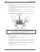
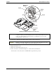
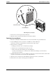
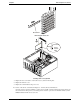
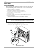
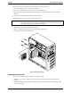
Table Of Contents
- 1 Specifications
- 2 Controls, Ports, and Indicators
- 3 Connector Pinouts
- 4 Maintenance Guidelines
- 5 Error Messages
- 6 Diagnostics
- 7 Maintenance and Troubleshooting
- Preventive Maintenance Procedures
- Troubleshooting
- Password Problems
- General Server Problems
- No lights are on and no error message appears
- Operating system or an application is not responding properly
- Server stops working (hangs)
- Server does not start (boot)
- Power Problems
- Video/Monitor Problems
- Configuration Problems
- Printer/Datacomm Problems
- Keyboard and Mouse Problems
- Flexible Disk Drive Problems
- CD-ROM Problems
- SCSI Problems
- Processor Problems
- Memory Problems
- Embedded Network Interface Card Problems
- Network Interface Card (Installed) Problems
- 8 Parts and Illustrations
- 9 Remove/Replace Procedures
- Introduction
- Covers
- Front Bezels
- Status Panel Assembly
- Mass Storage Devices
- Removing the Flexible Disk Drive
- Replacing the Flexible Disk Drive
- Removing the CD-ROM
- Replacing the CD-ROM
- Removing a Backup Tape Drive
- Replacing a Backup Tape Drive
- Removing a Hard Disk Drive (Tray Mounted)
- Replacing a Hard Disk Drive (Tray Mounted)
- Removing a Hard Disk Drive (Drive Cage Mounted)
- Replacing a Hard Disk Drive (Drive Cage Mounted)
- DIMMs
- Processor
- Accessory Boards
- Power Supply
- Battery
- Chassis Fan
- System Board
- Index
Chapter 9 Remove/Replace Procedures
93
Accessory Boards
Removing Accessory Boards
To remove an accessory board, refer to the following procedure.
1. If the Server is operating, power down the Server.
Refer to Chapter 2, “Controls, Ports, and Indicators” for instructions.
2. Disconnect the power cord and any external cables connected to the Server.
If necessary, label each one to expedite re-assembly.
3. Remove the left side cover.
WARNING The power supply will continue to provide standby current to the HP Server tc2100 until
the power cord is disconnected from the AC power source.
CAUTION Wear a wrist-strap and use a static-dissipating work surface connected to the chassis
when handling components. Ensure the metal of the wrist-strap contacts your skin.
4. Lay the Server on its side with the system board facing up (component side up).
5. Remove any cables attached to the accessory board.
If necessary, label each one to expedite re-assembly of a replacement board.
6. Remove the slot cover latch by:
a. Lift up on the tab of slot cover latch.
b. Raise the slot cover latch up from the slot covers.
c. Remove it from the chassis and keep it for reassembly.
You may need to lift the slot cover latch out of its retainer before lifting it out of the chassis.