Service manual
Table Of Contents
- 1 Specifications
- 2 Controls, Ports, and Indicators
- 3 Connector Pinouts
- 4 Maintenance Guidelines
- 5 Error Messages
- 6 Diagnostics
- 7 Maintenance and Troubleshooting
- Preventive Maintenance Procedures
- Troubleshooting
- Password Problems
- General Server Problems
- No lights are on and no error message appears
- Operating system or an application is not responding properly
- Server stops working (hangs)
- Server does not start (boot)
- Power Problems
- Video/Monitor Problems
- Configuration Problems
- Printer/Datacomm Problems
- Keyboard and Mouse Problems
- Flexible Disk Drive Problems
- CD-ROM Problems
- SCSI Problems
- Processor Problems
- Memory Problems
- Embedded Network Interface Card Problems
- Network Interface Card (Installed) Problems
- 8 Parts and Illustrations
- 9 Remove/Replace Procedures
- Introduction
- Covers
- Front Bezels
- Status Panel Assembly
- Mass Storage Devices
- Removing the Flexible Disk Drive
- Replacing the Flexible Disk Drive
- Removing the CD-ROM
- Replacing the CD-ROM
- Removing a Backup Tape Drive
- Replacing a Backup Tape Drive
- Removing a Hard Disk Drive (Tray Mounted)
- Replacing a Hard Disk Drive (Tray Mounted)
- Removing a Hard Disk Drive (Drive Cage Mounted)
- Replacing a Hard Disk Drive (Drive Cage Mounted)
- DIMMs
- Processor
- Accessory Boards
- Power Supply
- Battery
- Chassis Fan
- System Board
- Index

Chapter 9 Remove/Replace Procedures
90
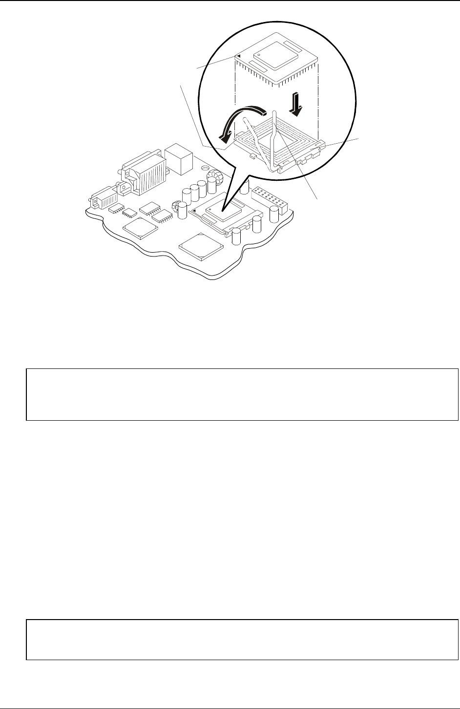
Pin-1
Marker
ZIF
Lever
Processor
Socket
Base
Replacing the Heatsink-Cooling Fan
Once the processor is installed, the heatsink-cooling fan must be installed on top of the processor. Each
processor requires a heatsink, with its cooling fan attached, and a thermal bonding between the processor and
the heatsink, provided with a thermal patch. The heatsink is mechanically connected to the processor socket
with both latches, mechanically making contact with processor through the thermal patch.
CAUTION To prevent overheating or a possible system crash, do not use the Celeron heatsink-
cooling fan assembly on a Pentium III processor. The Celeron heatsink-cooling fan
assembly uses a smaller fan and a little different heatsink and should not be used on the
Pentium III processor.
1. Remove the heatsink-fan assembly from the shipping container and ensure you do not touch the thermal
patch on the bottom of the heatsink.
2. Verify the thermal patch has not been damaged (missing thermal material from the patch) and if
necessary, remove the plastic tab protecting the thermal patch.
Some thermal patches have a small plastic sheet (with a finger tab) covering the non-adhesive side of
the patch to help protect the thermal material. This plastic sheet/tab must be removed before placing the
heatsink on the processor. The thermal patch used for the Celeron processors is smaller than the
thermal patch used by the Pentium III processors.
3. If the thermal patch has been damaged, peel it off the heatsink and replace it with a new one from the
installation kit.
It may help to use a felt-tip pen to mark an outline around the thermal patch on the bottom of the
heatsink, before removing the old patch. This may help you place the new patch on the heatsink.
4. Ensure the latches are free and pointing away from the heatsink.
CAUTION To prevent scratching off some of the thermal material, do not slide the heatsink around
on the processor once it is in place. Rocking it slightly to install the hook latch is
acceptable.
5. Position the heatsink over the processor and use one of two methods:


