
Service manual
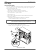
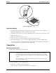
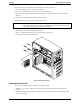
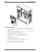

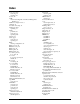
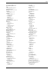
Table Of Contents
- 1 Specifications
- 2 Controls, Ports, and Indicators
- 3 Connector Pinouts
- 4 Maintenance Guidelines
- 5 Error Messages
- 6 Diagnostics
- 7 Maintenance and Troubleshooting
- Preventive Maintenance Procedures
- Troubleshooting
- Password Problems
- General Server Problems
- No lights are on and no error message appears
- Operating system or an application is not responding properly
- Server stops working (hangs)
- Server does not start (boot)
- Power Problems
- Video/Monitor Problems
- Configuration Problems
- Printer/Datacomm Problems
- Keyboard and Mouse Problems
- Flexible Disk Drive Problems
- CD-ROM Problems
- SCSI Problems
- Processor Problems
- Memory Problems
- Embedded Network Interface Card Problems
- Network Interface Card (Installed) Problems
- 8 Parts and Illustrations
- 9 Remove/Replace Procedures
- Introduction
- Covers
- Front Bezels
- Status Panel Assembly
- Mass Storage Devices
- Removing the Flexible Disk Drive
- Replacing the Flexible Disk Drive
- Removing the CD-ROM
- Replacing the CD-ROM
- Removing a Backup Tape Drive
- Replacing a Backup Tape Drive
- Removing a Hard Disk Drive (Tray Mounted)
- Replacing a Hard Disk Drive (Tray Mounted)
- Removing a Hard Disk Drive (Drive Cage Mounted)
- Replacing a Hard Disk Drive (Drive Cage Mounted)
- DIMMs
- Processor
- Accessory Boards
- Power Supply
- Battery
- Chassis Fan
- System Board
- Index
Chapter 9 Remove/Replace Procedures
101
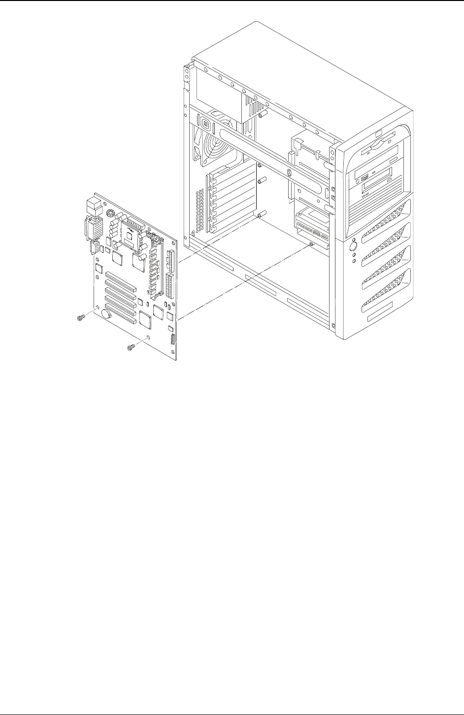
Replacing the System Board
1. Remove the replacement system board and any cables from the anti-static shipping container.
2. Place the system board on an anti-static pad and set all jumper connections as recorded during the
system board removal.
3. Place the system board in the chassis aligning the rear panel connectors to the rear chassis and the
mounting holes in the board with the holes in the chassis.
4. Install all the screws into the system board to secure it to the chassis.
5. Replace all cables that were disconnected during the previous removal.
6. Replace the DIMMs, processor and heatsink-cooling fan and accessory boards.
7. Replace the left side cover.
8. Return the Server to the upright position.
9. Connect the power cord and any external cables to the Server.
10. Power on the Server as described in Chapter 2, “Controls, Ports, and Indicators.”
11. Enter the (BIOS) Setup Utility and set the BIOS configuration.
12. Reboot the Server and verify the Server is operating correctly.