HP Tower Server tc2100 Service Manual Online Version 1.
Notice The information contained in this document is subject to change without notice. Hewlett-Packard makes no warranty of any kind with regard to this material, including, but not limited to, the implied warranties of merchantability and fitness for a particular purpose. Hewlett-Packard shall not be liable for errors contained herein or for incidental or consequential damages in connection with the furnishing, performance, or use of this material.
Contents 1 Specifications .........................................................................................................................................7 Technical Specifications............................................................................................................................7 Environmental .......................................................................................................................................7 Weight and Dimensions ........................
Contents HP DiagTools Capabilities ..................................................................................................................37 About Error Messages ........................................................................................................................38 Advantages and Limitations of Hardware Diagnostics .......................................................................38 7 Maintenance and Troubleshooting ........................................................
Contents Removing the Upper Bezel .................................................................................................................72 Replacing the Upper Bezel .................................................................................................................73 Removing the Lower Bezel .................................................................................................................74 Replacing the Lower Bezel ....................................................
1 Specifications Technical Specifications The specifications listed below for HP Tower Server tc2100 may vary if you install a mass storage device in your server that has more stringent environmental limits. Ensure the operating environment for your server is suitable for all of the mass storage devices being used.
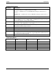
Chapter 1 Specifications Hardware Specifications Specification Characteristics Processors This HP Server supports Intel Celeron or Intel Pentium III processors (system board automatically detects processor FSB and changes accordingly): Intel Celeron - 850 MHz and above with 100 MHz FSB and Integrated 128K L2 cache on processor Intel Pentium III - 1.
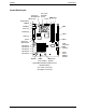
Chapter 1 Specifications System Board Layout Connector Heatsink Fan Processor, Heatsink & Fan DIMM Slots Power 3 2 1 Mouse (U) Keyboard (L) LAN (U) 2 USB (L) FDD Com 1 (L) Parallel (U) IDE-2 Video (L) IDE-1 Com 2 Connector Chassis Fan SCSI Controller LED Headers PCI Slot P1 PCI Slot P2 PCI Slot P3 PCI Slot P4 PCI Slot P5 Pin 3 Pin 1 Battery Front Panel Display Header Beep Code CMOS Clear Jumper Speaker System Board Components/Connectors Illustration Notes (L) = Lower connector(s) (U) = Upper
2 Controls, Ports, and Indicators Front Panel Control and Indicators The HP Tower Server tc2100’s controls, indicators, and user-serviceable internal components are shown in the following illustrations.
Chapter 2 Controls, Ports, and Indicators Flickering green LED during any embedded LAN activity. LAN Activity LED Off when there is no embedded LAN activity. Additional Front Panel Controls and Indicators The Mass Storage devices have additional controls and indicators providing the user with external controls to these devices and the related operational status. See the following table for Backup Tape drive LED Codes.
Chapter 2 Controls, Ports, and Indicators Rear Panel Ports and Features The following text and illustration describe the ports, switches, and unique features on the Server's rear panel. Power Input Voltage Switch Keylock Mouse LAN Keyboard USB (2) COM 1 System Fan Parallel Video COM 2 External SCSI (SCSI Model only) HP Server – Rear View • The power connector accepts a standard power cable to connect the HP Server tc2100 with the site power source.
Chapter 2 Controls, Ports, and Indicators • The LAN port is included as an embedded controller based on Intel's 82559 10/100 BaseT Fast Ethernet Controller. It has a RJ-45 LAN connector on the rear panel. The LED on the front panel is used to indicate LAN activity. • System Fan is a variable speed fan controlled by thermal sensors on the system board. The system fan speed can also be controlled by the fan speed settings in the (BIOS) Setup Utility.
Chapter 2 NOTE Controls, Ports, and Indicators The power supply will continue to provide standby current to the Server until the power cable is disconnected from the rear panel. Multiple-Server Configurations The HP Server temporarily draws a large "inrush current," when first connected to an AC power source. This also occurs when the Server is in a standby mode (power is turned off and the power cord is plugged into AC power).
Chapter 2 CAUTION Controls, Ports, and Indicators If the power button override is used; there is a strong possibility of corrupted or lost data. Refer to the BIOS Setup Utility in Chapter 8, “Configuring the HP Server” and your NOS documentation for instructions on setting up Sleep States and transitioning into and out of the various states.
3 Connector Pinouts Unless otherwise noted, the following features apply to all models. Some features are factory installed; others are optional.
Chapter 3 Connector Pinouts Parallel Port Connector 1 2 3 4 5 6 7 8 9 10 11 12 13 14 15 16 17 18 19 20 21 22 23 24 25 Parallel Connector Parallel Port Connector (female) Pinouts Pin Number Signal Description Pin Number Signal Description 1 Strobe5 10 Acknowledgeb 2 Data bit 06 11 Busy 3 Data bit 1a 12 Paper end 4 Data bit 2a 13 Select 5 Data bit 3a 14 Auto line feedb 6 Data bit 4a 15 Error1 7 Data bit 5a 16 Initialize printerb 8 Data bit 6a 17 Select inb 9 Data bit 7
Chapter 3 Connector Pinouts USB Connector 1 1 2 2 3 3 4 4 USB Connector Universal Serial Bus Connector Pinouts Pin Number Signal Description 1 VBUS 2 D+ 3 D- 4 GND NOTE Use of the USB port is supported for printers, scanners, and external modems. Video Connector The embedded video uses the standard 15-pin analog display pinout configuration. The pinouts for your monitor may vary. For the pinouts for your monitor, refer to the manual provided with your monitor.
Chapter 3 Connector Pinouts 68-Pin LVD SCSI Port Connector (Low Voltage Differential) Pin 1 LVD SCSI Connector (Male) Pin 68 68-Pin SCSI Port Connector Shown as pin matching Pin Number 20 Signal Description Pin Number Signal Description 1 +DB(12) 35 -DB(12) 2 +DB(13) 36 -DB(13) 3 +DB(14) 37 -DB(14) 4 +DB(15) 38 -DB(15) 5 +DB(P1) 39 -DB(P1) 6 +DB(0) 40 -DB(0) 7 +DB(1) 41 -DB(1) 8 +DB(2) 42 -DB(2) 9 +DB(3) 43 -DB(3) 10 +DB(4) 44 -DB(4) 11 +DB(5) 45 -DB(5)
Chapter 3 Connector Pinouts 50-Pin Narrow SCSI Port Connector – Accessory Board Position 25 Position 1 Position 50 Position 26 SCSI Port Connector 50-Pin Narrow SCSI Port Connector Pinouts Pin Number Signal Description Pin Number Signal Description 1-11 Ground 37 Reserved 12 Reserved 38 Termpwr 13 Open 39 Reserved 14 Reserved 40 Ground 15-25 Ground 41 -ATN 26 -DB(0) 42 Ground 27 -DB(1) 43 -BSY 28 -DB(2) 44 -ACK 29 -DB(3) 45 -RST 30 -DB(4) 46 -MSG 31 -DB(5)
Chapter 3 Connector Pinouts Pin Number Signal Description 3 Ground 4 Power (+5 V dc) 5 Clock signal 6-8 Not used 22
4 Maintenance Guidelines Introduction This chapter provides the HP Tower Server tc2100’s maintenance guidelines when removing or replacing the mass storage devices, DIMM memory, accessory boards, and processors. Mass Storage The HP Server tc2100 comes standard with one IDE CD-ROM and one flexible disk drive with various possible configurations of SCSI or IDE hard disk drives, depending on the model (SCSI or IDE).
Chapter 4 Maintenance Guidelines o Use only HP Ultra-160 SCSI LVD (1-inch) low profile 3.5-inch hard disk drives for the removable hard disk drive cage. o Only use an HP Ultra-160 SCSI LVD drive as the optional third drive. o The optional HP backup tape drive comes with a 50-to-68-pin adapter to connect to the 68-pin SCSI connector on the SCSI cable used for connection of backup tape drive. o The optional HP backup tape drive may slow down access time for the Ultra-160 SCSI hard drives.
Chapter 4 Maintenance Guidelines IDE Mass Storage Devices This section provides the configuration of the IDE mass storage devices, if you have selected an IDE version of the HP Server tc2100. IDE Controller Configuration The embedded IDE controller is available for both models (IDE or SCSI) of the HP Server. The embedded IDE controller is an Ultra DMA33/66/100 E-IDE dual channel controller, which provides IDE-1 and IDE-2 connectors. Each channel can only control two IDE devices.
Chapter 4 Maintenance Guidelines • 1 external 68-pin connector – This external SCSI connector is only used for external SCSI devices and requires no additional internal cabling or switch settings. This connector supports up to 15 devices connected to it externally. NOTE Only one 68-pin connector on the SCSI controller board can be used as the active SCSI connector.
Chapter 4 Maintenance Guidelines SCSI Mass Storage Additions The table below lists the number and types of mass storage devices in or may added into the SCSI model of the HP Server. SCSI Model Mass Storage Devices Interface Types Max No. Devices FDD 1 Factory installed flexible disk drive (FDD) in shelf 1 IDE-2 2* Factory installed CD-ROM drive in shelf 2 Installed Devices and Addresses A second IDE device (hard disk drive) could be installed, if shelf 3 is available.
Chapter 4 Maintenance Guidelines http://www.hp.com/go/Server • HP Customer Service The video memory is limited to 4 MB on the system board and cannot be upgraded. Accessory Board Guidelines The system board in the HP Server tc2100 provides up to five 32-bit PCI slots (P1 through P5).
Chapter 4 Maintenance Guidelines • Ensure the front ridge on the bottom of the heatsink fits into the groove between the processor socket and processor and both ridges should straddle the processor. The bottom of each heatsink has two ridges, which are used to align the heatsink with the processor. • Both latches (hook and thumb) on the heatsink must be connected to the processor socket base or the processor will overheat.
5 Error Messages Introduction This chapter describes the beep codes and the POST error codes that may occur during the boot process or normal operation of the HP Tower Server tc2100. Beep Codes If the POST routines cannot display messages when an error occurs before the video display is initialized, the HP Server emits a series of beeps. If you get a blank screen on boot, but hear beeps, refer to the table below to interpret the meaning of the beeps.
Chapter 5 Error Messages Error Code Description (Extended Errors) Problem/Solution 0200 POST has detected the specified hard disk drive is not responding, but is configured in the Setup Utility. Fixed Disk Failure To correct this: 1. If the specified hard disk has just been removed, press to automatically validate the change. 2. Verify all data cables and power cables are firmly connected. 3. If the cable is damaged, connect the hard disk drive to another IDE cable, if available. 4.
Chapter 5 0251 Error Messages System CMOS checksum bad – (Default configuration used) The BIOS configuration has been lost, cleared, corrupted, or has not been initialized. When the HP Server remains unplugged for a long period of time, the battery will discharge and not provide enough current to keep the CMOS memory powered. To correct this: 1. Verify the battery is properly inserted. 2. If necessary, replace the battery as described in your in this manual or the Installation Guide. 3.
Chapter 5 0280 Error Messages Previous boot incomplete The HP Server configuration has been cleared or has not been initialized and the Default configuration has been used instead. • Run the Setup Utility to re-configure your system. 0281 DIMM size boot error The system memory (DIMMs) size detected during POST is smaller than previously detected. One or several DIMMs are disconnected, or have been replaced by smaller size DIMMs. To correct this: 1.
Chapter 5 0231 Error Messages Shadow Ram Failed (at offset) POST has detected an incorrectly installed DIMM or the failure of one or more DIMMs. To correct this: 1. If additional memory was just installed in your Server, please verify the installation conforms to the description in the Installation Guide. 2. If this error is reported when no additional memory has just been installed, restart the Server. 3. If the error persists, contact your service representative.
Chapter 5 Error Messages Code Description (System Monitor Errors) Problem/Solution 0A01 Emergency shutdown occurred (system initiated) The Server has performed an emergency shutdown to prevent damage to system board. • To prevent unstable behavior, or a system hang during the boot process, do not skip this error message or continue with Server operation. To verify this error: 1. Reboot the Server. 2.
6 Diagnostics Diagnostic Tests When the Server boots, a series of tests are displayed on the screen. The number of tests displayed depends on the configuration of the Server. The following are the types of errors a user might get with the HP Server. • Built-in diagnostic Error Messages. • BIOS and other error messages. These are errors detected by the system BIOS outside the built-in diagnostics or application errors.
Chapter 6 Diagnostics The HP DiagTools Utility is run from the Startup CD-ROM, which is a bootable CD-ROM when inserted into the CD-ROM drive and the Server is rebooted. A basic suite of tools checks key Server components, and a menu of advanced tests is available for in-depth testing.
Chapter 6 Diagnostics • No access to operating system error logs, since the OS is not operating at the same time as the diagnostic tools • Limited ability to test only a single component at a time • Inability to indicate problems with wrongly configured Servers or the network 39
7 Maintenance and Troubleshooting Preventive Maintenance Procedures Refer to the following table for preventive maintenance procedures used for the HP Tower Server tc2100. Be sure to turn off power to the Server when cleaning it. Preventative Maintenance Procedures Component Time Frame Maintenance Procedure Keyboard Regularly Dust with damp, lint-free cloth. Monitor screen Regularly Use "HP Video Screen Cleaning Solution" found in 92193M Master Clean Kit.
Chapter 7 Maintenance and Troubleshooting • Remove all options added since the Server was received and then add one option, and only one option, at a time. NOTE If the Server has a large amount of memory installed, it may take 30 seconds for the first screen to display. If it is a hardware error, follow these steps: 1. Log users off the network, and if necessary backup the Server. 2. Power down the Server and disconnect the power cord from the AC power source.
Chapter 7 Maintenance and Troubleshooting Refer to “Processor Problems” later in the chapter. Server Powers On, but Fails POST Do one of the following: • If the Server fails POST and an error message appears, refer to Chapter 5, "Error Messages.” • If the suggested solutions do not solve the problem, contact HP or your reseller. Server Passes POST, but Does Not Function If an error message appears, read the error message text for actions to take. Also, refer to Chapter 5, "Error Messages.
Chapter 7 Maintenance and Troubleshooting BIOS Reset If you need to reset your BIOS settings to the factory defaults (the HP recommended values) due to possible corruptions, perform the following steps. The default values have been selected to optimize the HP Server’s performance. 1. Reboot the Server in a normal manner and press to enter the BIOS Setup Utility. 2. Press to load default values. 3. Press F10 to save changes and exit the BIOS Setup Utility.
Chapter 7 Maintenance and Troubleshooting 1. Turn off power to the Server and remove the left side cover. 2. Move the jumper from its “Normal” position (Pins 1 & 2) on the system board to the “Clear CMOS” position (Pins 2 & 3) and leave it there for five seconds as shown in the figures below. Pin 3 Pin 1 Battery Spring CMOS Latch Clear Jumper Configuration Switch Location Pin 3 Pin 1 Normal Clear CMOS CMOS Jumper Settings 3.
Chapter 7 Maintenance and Troubleshooting 1. Verify the power is good and available. 2. Ensure the Server is turned on (the power-on light should be green and the fans should be on). 3. Turn the Server off and unplug the power cord. a. Wait 30 seconds and plug the power cord back in. b. Turn the Server back on. c. Verify the failure. 4. Verify all boards are installed properly and seated firmly in the slots with cables firmly connected. 5.
Chapter 7 Maintenance and Troubleshooting NOTE The POST error messages may reflect which modules are defective and should be replaced. 2. Review the Troubleshooting Checklist before you continue. 3. Power the Server off and on (instead of using Ctrl-Alt-Del). Powering the server off and on is a more complete system reset. 4. If POST reports a problem, check the error against the Error Messages and correct the problem. Refer to Chapter 5, "Error Messages.” 5.
Chapter 7 Maintenance and Troubleshooting Typically, all fans run when power is turned on and all fans are off when the power is turned off. 5. With the power supply connected to the system board, check the power supply's voltages. 6. If voltages are not present: a. Turn off AC power. b. Disconnect the power cord for 5 minutes in order to reset the power supply's circuitry. c. Turn on AC power again. d. If power is still not getting to the system board, replace the power supply. e.
Chapter 7 Maintenance and Troubleshooting a. Unplug the power cord and wait 30 seconds. b. Plug in the power cord and turn on the Server. c. Wait a full 2 minutes. d. Verify the monitor starts displaying normally. 10. Check the monitor display to see if the system memory count takes place correctly: a. Turn the Server off and then on. b. Check to see if the memory is counted during the Server boot. If no count occurs, go to Step 12. c.
Chapter 7 Maintenance and Troubleshooting 17. If the customer has installed a video board instead of using the embedded video, ensure all jumpers and switches are set properly on the installed video board. Refer to the user manual provided with the video board. 18. If the monitor displays a badly scrambled image that looks to be the current screen image, then the monitor is not synchronizing correctly. a. If a video board is installed, replace it with a known good one.
Chapter 7 Maintenance and Troubleshooting Symptom: • The configuration information is frequently lost and the battery is good. If the battery is good and you cannot save system configuration, do the following 1. Review the Troubleshooting Checklist before you continue. BIOS configuration information is saved in the CMOS memory. 2. If you continue to loose configuration information and the battery is good, or you cannot save the BIOS information to CMOS memory: a.
Chapter 7 Maintenance and Troubleshooting Keyboard and Mouse Problems Symptoms: • The keyboard does not work • A character is not displayed when a key is pressed 1. Review the Troubleshooting Checklist before you continue. 2. Ensure the keyboard is not locked. 3. Ensure the keyboard cable connections at the rear of the Server and at the back of the keyboard are securely and correctly attached. 4.
Chapter 7 Maintenance and Troubleshooting 4. Select the Setup Utility (press [F2] during the boot process and verify the Server's mass storage configuration is correct. a. If for some reason you cannot run the Setup, you can clear CMOS and reconfigure the Server. b. Try to reboot. 5. If you cannot format or write to a flexible disk: o Ensure diskette is not write-protected o Ensure flexible disk drive is properly configured with the Setup Utility and you have access privileges. 6.
Chapter 7 Maintenance and Troubleshooting Symptom: • The CD-ROM drive is not working properly The CD-ROM drive provided with this HP Server (SCSI or IDE models) is IDE CD-ROM. If the CD-ROM drive does not work, do the following: 1. Review the basic IDE installation guidelines to ensure a proper configuration. 2. In addition, check the following: o Verify correct drivers are installed. o Verify there is a CD-ROM disk in the CD-ROM drive.
Chapter 7 Maintenance and Troubleshooting Symptom: • The SCSI controller board does not work during installation Usually an incorrect configuration and not faulty hardware causes most of the SCSI problems encountered during installation. If the SCSI controller does not work after installation, do the following: 1. Review the Troubleshooting Checklist and Mass Storage Guidelines before you continue. 2.
Chapter 7 Maintenance and Troubleshooting For example, in this Server with 1 SCSI controller and 2 hard disk drives (one with ID 0 and one with ID 1), if a valid device is found at device address 0, but not at address 1, you would see these device validation lines on the boot screen: Channel x, SCSI ID #n - id info - Drive C: (80h) If you see this message: a. Verify the SCSI hard disk drive is set to address 1. b.
Chapter 7 Maintenance and Troubleshooting a. Remove the new board and restart the Server. b. If this corrects the problem, the board is either defective or it is trying to use a system resource used by the SCSI controller board. c. Check if the board is using memory, I/O addresses, or interrupt lines that are also used by the SCSI controller board. 5. Check for any recent changes or upgrades to the software.
Chapter 7 Maintenance and Troubleshooting 9. Ensure no SCSI device is set to SCSI address ID = 7. This address ID is the reserved for the SCSI controller. 10. Verify all SCSI devices are low voltage differential (LVD) SCSI devices, and there are no single-ended devices on the bus. 11. Verify the SCSI hard disk drive that loads the operating system is set to the lowest SCSI address (usually set to 0). 12.
Chapter 7 Maintenance and Troubleshooting c. If the error goes away, add another DIMM and reboot again. d. Continue this process until you have installed all DIMMs or you experience a failure. e. Replace the defective DIMM. 7. Once a suspect part has been found, verify the cause of the problem by reinstalling the part and attempting to duplicate the error. Also install it in another memory socket to confirm whether or not the socket is defective.
8 Parts and Illustrations Exploded View – Covers and Bezels 1 2 8 3 4 7 6 5 61
Chapter 8 Parts and Illustrations Exploded View – Mass Storage Devices 9 10 11 12 13 14 20 15 19 16 17 18 62
Chapter 8 Parts and Illustrations Exploded View – Chassis Fan, Power Supply, and System Board Rear View 21 26 25 24 23 22 63
Chapter 8 Parts and Illustrations Exploded View – System Board Components 27 28 29 32 31 30 64
Chapter 8 Parts and Illustrations Replaceable Parts List The items in this list and the corresponding item numbers in the respective Exploded Views apply to both models of the HP Server, except where noted. NOTE The part numbers listed below were available at the time of publication. Part numbers may change after publication. Order parts by the number listed below; HP's parts price list database will generally contain a reference to the revised part number.
Chapter 8 Parts and Illustrations Item No.
Chapter 8 Parts and Illustrations Language Part Number Language Part Number Polish D4950-63035 Swedish D4950-63012 Hungarian D4950-63037 UK D4950-63013 Turkish D4950-63035 Czech D4950-63036 Greek D4950-63032 Dutch D4950-63006 Power Cords Country Part Number Country Part Number Australia/New Zealand 8120-1369 India/South Africa 8120-4211 Canada/United States 8120-1751 Denmark 8120-2956 Switzerland 8120-2104 Europe 8120-1689 United Kingdom 8120-1351 67
9 Remove/Replace Procedures Introduction This chapter describes the removal and replacement procedures for the user serviceable components in the HP Tower Server tc2100. Safety Information Follow the procedures listed below to ensure safe handling of components and to prevent harm to both you and the server: • Use an anti-static wrist strap and a grounding mat, such as those included in the Electrically Conductive Field Service Grounding Kit (HP 9300-1155).
Chapter 9 Remove/Replace Procedures 2. Power down the Server and disconnect the power cord and any phone lines. 3. If necessary, unlock the left side cover, using the lock located on the rear of the Server. The locking mechanism is at the rear, as shown below. Initially, the keys are attached to the rear of the HP Server, similar to the view shown below. Turn Key to Unlock Unlocking the Left Side Cover 4. Open the latch by lifting it up and out on the left side cover, to release the side cover. 5.
Chapter 9 Remove/Replace Procedures Removing the Left Side Cover 6. Place the left side cover in a safe place for re-installation later. Replacing the Left Side Cover To replace the left side cover, follow these steps: 1. If you have been installing accessories or servicing the Server, return the Server to its normal upright position. 2. Use two hands to place the side cover’s lower edge at an angle to the hinge latches along the bottom of the chassis.
Chapter 9 Remove/Replace Procedures Latch Hinge Tabs Replacing the Left Side Cover Alternate Covers The other covers (top or right side) used on the Server are not essential when accessing components in or on the Server. However, if for some reason you need to replace one of these covers you can find both covers illustrated in some detail in the exploded view of Chapter 8, “Parts and Illustrations.
Chapter 9 Remove/Replace Procedures This action will swing the upper front bezel open on its hinge teeth. 6. Swing the upper bezel completely open and remove it from the front of the Server. Release Tabs (2) Removing the Upper Front Bezel Replacing the Upper Bezel The upper front bezel uses hinge teeth, instead of a normal hinge assembly, to engage each side of the hinge and pivots on these when opening or closing the upper bezel. 1.
Chapter 9 Remove/Replace Procedures Hinge Teeth (4) Replacing the Upper Bezel Removing the Lower Bezel 1. If the Server is operating, power down the Server. Refer to Chapter 2, “Controls, Ports, and Indicators” for instructions. 2. Disconnect the power cord and any external cables connected to the Server. If necessary, label each one to expedite re-assembly. 3. Remove the left side cover. 4. Remove the upper bezel as describe in the previous procedures. 5.
Chapter 9 Remove/Replace Procedures C A B Removing the Lower Bezel Replacing the Lower Bezel 1. If the Server is operating, power down the Server. Refer to Chapter 2, “Controls, Ports, and Indicators” for instructions. 2. Disconnect the power cord and any external cables connected to the Server. If necessary, label each one to expedite re-assembly. 3. Remove the left side cover. 4. Remove the upper bezel. 5.
Chapter 9 Remove/Replace Procedures 2. Disconnect the power cord and any external cables connected to the Server. If necessary, label each one to expedite re-assembly. 3. Remove the left side cover. 4. Remove the upper bezel. 5. Remove the lower bezel. 6. Disconnect the status panel connector(s) from the header pins on the system board. 7. Remove the screw holding the status panel assembly to the chassis. You must access the head of the screw from inside the chassis, as shown in following illustration. 8.
Chapter 9 Remove/Replace Procedures 8. Restore power to the Server and verify the status panel assembly is working properly. Mass Storage Devices Shelf 1 (FDD) Shelf 2 (CD-ROM) Shelf 3 (Backup Tape Drive) (Optional) Latch Release (Drive Cage) Shelf 5 (2nd Hard Drive) (Optional) Mass Storage Device Locations Removing the Flexible Disk Drive 1. If the Server is operating, power down the Server, and if necessary, backup mass storage devices.
Chapter 9 Remove/Replace Procedures A B C Removing the Flexible Disk Drive (FDD) 7. Rotate the FDD mounting assembly off of the flexible disk drive. 8. Place the flexible disk drive in an anti-static bag. Replacing the Flexible Disk Drive 1. If not already mounted, place the two hooks in the screw holes on the right side of the FDD and rotate the FDD mounting assembly onto the flexible disk drive. 2. Secure the FDD mounting assembly on the flexible disk drive by inserting the two screws. 3.
Chapter 9 Remove/Replace Procedures 4. Remove the upper bezel. 5. At the rear of the CD-ROM, carefully disconnect the power and data cables. 6. Remove the CD-ROM by: a. Pressing in on both release tabs to release the CD-ROM tray assembly. b. Pull the CD-ROM assembly out of the chassis. c. Remove the four screws, two from both sides of the CD-ROM tray. 7. Place the CD-ROM in an anti-static bag. A B C Removing the CD-ROM Replacing the CD-ROM 1. Remove the CD-ROM from the shipping container. 2.
Chapter 9 Remove/Replace Procedures The IDE CD-ROM uses one connector on the cable from the IDE-2 connector, leaving one connector for the optional third hard drive on the IDE model. 7. Replace the upper bezel. 8. Replace the left side cover. 9. Replace the external cables and power cord. 10. Power on the Server as described in Chapter 2, “Controls, Ports, and Indicators.” Removing a Backup Tape Drive This procedure is used to remove the optional HP Backup Tape Drive mounted in the third shelf. 1.
Chapter 9 Remove/Replace Procedures 2. Make any settings required by the HP Backup Tape Drive documentation. The SCSI backup tape drive should not be terminated, but if it is remove the termination jumper. The default SCSI address for HP Backup Tape Drive is normally set to ID address = 3. 3. Attach the backup tape drive to third mounting tray using the four screws on the sides of the tray.
Chapter 9 Remove/Replace Procedures B A A C Removing Hard Disk Drive (HDD) and Tray Replacing a Hard Disk Drive (Tray Mounted) This procedure is used to replace the third hard disk drive (HDD) mounted in the fourth shelf. The second and third drive trays are identical, but the forth drive tray is reserved for a hard drive (IDE or SCSI). The fourth drive tray provides four raised mounting posts to mount hard drives without the use of any mounting brackets. 1.
Chapter 9 Remove/Replace Procedures 7. Replace the left side cover. 8. Replace the external cables and power cord. 9. Power on the Server as described in Chapter 2, “Controls, Ports, and Indicators.” Removing a Hard Disk Drive (Drive Cage Mounted) The replacement of the mass storage cage mounted drives is the same for IDE or SCSI drives. CAUTION Install and remove connectors carefully, and avoid displacing any pins. 1. If the Server is operating, power down the Server.
Chapter 9 Remove/Replace Procedures Replacing a Hard Disk Drive (Drive Cage Mounted) 1. If the drive cage is already removed from the chassis, perform the following procedure starting at Step 3. 2. If it is necessary to remove the drive cage from the chassis, perform steps 3 through 6 of the proceeding removal procedure. NOTE If the hard disk drive (HDD) you are planning to install already has a mounting tray attached, you must remove it before you can install the drive into the drive cage. 3.
Chapter 9 Remove/Replace Procedures For the SCSI model, use the SCSI cable, which has 5 connectors and a termination on the end of the cable. Typically, the SCSI cable is already folded, allowing you to use the available connectors on the SCSI cable nearest the drive cage. 9. Connect the power cables to all the drives in the drive cage. 10. Replace the left side cover. 11. Replace the external cables and power cord. 12. Power on the Server as described in Chapter 2, “Controls, Ports, and Indicators.
Chapter 9 Remove/Replace Procedures DIMM Slots 3 2 1 System Board Removing DIMMs from System Board Replacing DIMMs 1. Choose a DIMM slot for the desired DIMM. DIMM sizes may be mixed on the system board and may be loaded in any order (1 through 3). However, HP recommends starting at slot 1 and filling the slots in order: 1, 2, and 3. Empty slots between DIMMs are permitted. 2. Spread the two retaining latches on the slot outward. CAUTION Use only HP DIMMs, which are 168-pin, 3.
Chapter 9 Remove/Replace Procedures Notches Keys Retaining Latches DIMM Slot DIMM to Slot Alignment 5. Holding the DIMM at 90 degrees to the system board, press the DIMM fully into the slot until the retaining latches close. If the latches do not close, the DIMM is not inserted correctly. 6. Repeat Steps 1-5, to install all of the remaining DIMMs for your memory configuration. 7. Replace the left side cover. 8. Replace the external cables and power cord. 9.
Chapter 9 Remove/Replace Procedures WARNING The power supply will continue to provide standby current to the HP Server until the power cord is disconnected from the AC power source. 4. Lay the Server on its side (components showing). 5. Disconnect the cooling fan power cable from the connector on the system board. 6. Remove the heatsink by: a. Unhooking the thumb latch on the heatsink and lifting the heatsink up slightly from the processor.
Chapter 9 Remove/Replace Procedures Pin-1 Marker Processor Socket Base ZIF Lever Removing the Processor 3. Grasp the processor by its edges and lift it out of the processor socket. 4. Place the processor on a static-dissipating work surface or into an anti-static bag. Replacing the Processor 1. Locate the pin-1 marker on the processor before installing the processor.
Chapter 9 Remove/Replace Procedures Pin-1 Marker Processor Socket Base ZIF Lever Replacing the Heatsink-Cooling Fan Once the processor is installed, the heatsink-cooling fan must be installed on top of the processor. Each processor requires a heatsink, with its cooling fan attached, and a thermal bonding between the processor and the heatsink, provided with a thermal patch.
Chapter 9 Remove/Replace Procedures Method A a. Position the heatsink over the processor socket and lower it squarely onto the processor, as shown in the following illustration. There are two ridges on the heatsink to help align the heatsink to the processor. The heatsink can only be installed in one direction, with the metal step to the right of processor socket, as shown in the following illustration. b.
Chapter 9 Remove/Replace Procedures Hook Latch (hidden) Step A Thumb Latch Tab Step C Tab Step B Processor Socket Base Replacing Heatsink-Cooling Fan on the Processor CAUTION Ensure you have made good contact with the processor to avoid thermal overheating. If you have not made good contact with the processor, it will overheat within 20 seconds of power on, possibly causing a system crash before completing the boot process and causing damage to the processor. 6.
Chapter 9 Remove/Replace Procedures Accessory Boards Removing Accessory Boards To remove an accessory board, refer to the following procedure. 1. If the Server is operating, power down the Server. Refer to Chapter 2, “Controls, Ports, and Indicators” for instructions. 2. Disconnect the power cord and any external cables connected to the Server. If necessary, label each one to expedite re-assembly. 3. Remove the left side cover.
Chapter 9 Remove/Replace Procedures A. C. B. Slot Cover Latch Latch Retainer Removing Slot cover Latch 7. Lift the accessory board up and away from the slot. 8. Place the accessory board and any cables in an anti-static container. Replacing Accessory Boards 1. Read the documentation included with the accessory board and follow any special instructions. 2. If your installing the accessory board into a new PCI slot, continue with Step 3.
Chapter 9 Remove/Replace Procedures Slot Cover Removing the Slot Cover Slot Cover Chassis CrossSection View Inserting an Accessory Board 7. Replace the slot cover latch to ensure the accessory board is held in place. 8. Replace the left side cover. 9. Replace the external cables and power cord. 10. Power on the Server as described in Chapter 2, “Controls, Ports, and Indicators.” Once the accessory board is installed, you may need to install or update software drivers.
Chapter 9 Remove/Replace Procedures Power Supply Removing the Power Supply The low voltage ON/OFF switch on the front panel controls the power supply and the voltage selector switch on the rear panel adapts the power supply to the input AC voltage. To remove the power supply from the chassis, perform the following procedure. 1. If the Server is operating, power down the Server. Refer to Chapter 2, “Controls, Ports, and Indicators” for instructions. 2.
Chapter 9 Remove/Replace Procedures 6. If the power supply is defective and the replacement power supply does not have the mounting bracket, remove the mounting bracket from the defective supply before going to the next procedure. Replacing the Power Supply 1. Place the power supply into the chassis and connect the mounting bracket to the top of the chassis. 2. Slide the power supply toward the rear of the chassis with the mounting bracket attached to the inside of the chassis. 3.
Chapter 9 Remove/Replace Procedures View Rotated 90 Degrees CCW Removing the Battery Replacing the Battery 1. Insert the new battery with the positive sign (+) facing out, and ensure that it is seated completely. Ensure the retaining latch is in place, and holds the battery firmly. 2. If necessary, replace any accessory boards or SCSI cables removed to allow access to the battery socket. 3. Replace the left side cover. 4. Replace the external cables and power cord. 5.
Chapter 9 Remove/Replace Procedures 2. Disconnect the power cord and any external cables connected to the Server. If necessary, label each one to expedite re-assembly. 3. Disconnect the chassis fan’s power connector from the system board. 4. Remove the fan by placing a sharp flat object (screwdriver or knife) under the edge of the mounting snap rivet. 5. Lift the snap rivet away from the surface of the rear chassis. 6. Remove the snap rivet housing from the rear of the chassis.
Chapter 9 Remove/Replace Procedures 4. Repeat Step 3 for the three-remaining snap rivet housings and snap rivets. 5. Connect the chassis fan’s power connector. 6. If necessary, replace any accessory boards removed to allow clear access to the fan. 7. Replace the left side cover. 8. Replace the external cables and power cord. 9. Power on the Server as described in Chapter 2, “Controls, Ports, and Indicators.” 10. Verify the chassis fan is operating correctly. System Board Removing the System Board 1.
Chapter 9 Remove/Replace Procedures Replacing the System Board 1. Remove the replacement system board and any cables from the anti-static shipping container. 2. Place the system board on an anti-static pad and set all jumper connections as recorded during the system board removal. 3. Place the system board in the chassis aligning the rear panel connectors to the rear chassis and the mounting holes in the board with the holes in the chassis. 4.
Index accessory boards removing, 95 replacing, 96 acetone, 43 ACPI Advanced Configuration and Power Management Interface, 11 AGP video display modes, 8 ammonia, 43 anti-static wrist strap, 71 backup tape drive replacing, 83 battery problems, 52 removing, 99 replacing, 100 benzene, 43 bezel, upper removing, 74 replacing, 75 BIOS clearing configuration, 47 BIOS recovery, 45 BIOS Recovery, 46 BIOS reset, 45 BIOS update, 45 BIOS Update, 46 boot device priority boot order, 26 boot order boot device priority, 26
Index front side bus (FSB), 31, 91 front side bus speed, 31, 91 FSB Front Side Bus speed, 91 FSB speed, 31, 91 general information, 7, 11, 33 heatsink thermal patch, 31, 92 heatsink alignment ridges, 31 hook latch, 93 mounting, 93 ridges, 31 thermal patch, 92 thumb latch, 93 HP NetRAID M1 Controller, 28 HP Server controls, 11 inrush current, 16 ports, 11 powering down, 15 powering up, 15 HP Tape Drive error codes, 12 IDE CD-ROM Cable, 68 IDE HDD cable, 68 inrush current, 16 installation additional memory,
Index processor Pin-1 marker, 30, 91 processor heatsink-cooling fan, 60 heatsink-cooling fan, 93 problems, 60 removing, 89 replacing, 91 processor socket Pin-1 marker, 30, 91 processors overheating, 94 read/write errors, 55 replacing parts, 71 SCSI external connector, 15 Problems, 59 SCSI controller ID, 26 SCSI port 50-pin connector, 23 68-pin connector, 22 security keylock, 15 serial port connectors, 19 serial ports, 14 shelf HDD replacing, 84 shelf mounted removing hard disk drive, 82, 83 Sleep States, 1