Troubleshooting Guide HP t5325 Thin Clients
© Copyright 2009 Hewlett-Packard Development Company, L.P. The information contained herein is subject to change without notice. Microsoft and Windows are trademarks of Microsoft Corporation in the U.S. and other countries. The only warranties for HP products and services are set forth in the express warranty statements accompanying such products and services. Nothing herein should be construed as constituting an additional warranty.
About This Book WARNING! Text set off in this manner indicates that failure to follow directions could result in bodily harm or loss of life. CAUTION: Text set off in this manner indicates that failure to follow directions could result in damage to equipment or loss of information. NOTE: Text set off in this manner provides important supplemental information.
iv About This Book
Table of contents 1 Product Description ........................................................................................................................................ 1 Product features ................................................................................................................................... 1 Serial Number Location ....................................................................................................... 1 Front Panel Components .............................
No Internal Network Connection ....................................................................... 26 No Audio ........................................................................................................... 27 No IP Address ................................................................................................... 28 5 Restoring the Flash Image ...........................................................................................................................
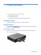
1 Product Description The following features are common to all HP thin clients: ● no hard drives or diskette drives ● 5-minute hardware setup time ● central deployment and management using HP Management Solutions Operating systems The t5325 thin client offers an extensible Linux image built upon Debian. Product features For more information, http://www.hp.com and search for your specific thin client model to find the model-specific QuickSpecs.
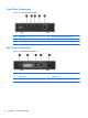
Front Panel Components Figure 1-2 Front panel components (1) Power button (4) Line-out (headphone) audio connector (2) Flash activity LED (5) Universal serial bus (USB) connectors (2) (3) Line-in (microphone) connector Rear Panel Components Figure 1-3 Rear panel components 2 (1) Power connector (4) Ethernet RJ-45 connector (2) DVI-I connector (5) Cable lock slot (3) Universal serial bus (USB) connectors (2) Chapter 1 Product Description
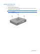
Installing the Rubber Feet To install the rubber feet: 1. Remove the feet from their backing. 2. Line up the hole in each foot with a VESA hole on the bottom of the thin client. Press the foot down firmly to secure it to the thin client. NOTE: The feet provide a protective cushion between the thin client and whatever surface it sits on or is mounted to.
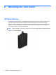
2 Mounting the Thin Client HP Quick Release This thin client incorporates four mounting points on the bottom of the unit. These mounting points follow the VESA (Video Electronics Standards Association) standard, which provides industrystandard mounting interfaces for Flat Displays (FDs), such as flat panel monitors, flat displays, and flat TVs. The HP Quick Release connects to the VESA-standard mounting points, allowing you to mount the thin client in a variety of orientations.
To use the HP Quick Release: 1. Using four 10 mm screws included in the mounting device kit, attach one side of the HP Quick Release to the thin client as shown in the following illustration. Figure 2-2 Connecting the HP Quick Release to the thin client 2. Using four screws included in the mounting device kit, attach the other side of the HP Quick Release to the device to which you will mount the thin client. Make sure the release lever points upward.
3. Slide the side of the mounting device attached to the thin client (1) over the other side of the mounting device (2) on the device on which you want to mount the thin client. An audible 'click' indicates a secure connection. Figure 2-4 Connecting the thin client NOTE: When attached, the HP Quick Release automatically locks in position. You only need to slide the lever to one side to remove the thin client.
Supported Mounting Options The following illustrations demonstrate some of the supported and not supported mounting options for the mounting bracket. ● You can mount a thin client between a flat panel monitor and the wall. Figure 2-5 Thin client mounted with flat panel on wall ● You can mount the thin client on the back of a flat panel monitor stand. Figure 2-6 Thin client mounted on back of monitor stand ● You can mount the thin client on a wall.
Figure 2-7 Thin client mounted on wall ● You can mount the thin client under a desk. Figure 2-8 Thin client mounted under desk Non-supported Mounting Option CAUTION: Mounting a thin client in an non-supported manner could result in failure of the HP Quick Release and damage to the thin client and/or other equipment. Do not mount the thin client on a flat panel monitor stand between the panel and the stand.
Figure 2-9 Unsupported mounting position—thin client between stand and monitor HP Quick Release 9
3 Thin Client Operation Routine Thin Client Care Use the following information to properly care for your thin client: ● Never operate the thin client with the outside panel removed. ● Keep the thin client away from excessive moisture, direct sunlight, and extreme heat and cold. For information about the recommended temperature and humidity ranges for the thin client, see Specifications on page 31. ● Keep liquids away from the thin client and keyboard.
Figure 3-2 Under monitor stand Non-supported Orientation HP does not support the following orientations for the thin client. CAUTION: Non-supported placement of thin clients could result in operation failure and/or damage to the devices. Thin clients require proper ventilation to maintain operating temperature. Do not block the vents. Do not put thin clients in drawers or other sealed enclosures. Do not place a monitor or other object on top of the thin client.
Figure 3-4 Do not place a monitor on the thin client 12 Chapter 3 Thin Client Operation
4 Diagnostics and Troubleshooting LEDs Table 4-1 Power and IDE Flash Activity LEDs LED Status Power LED Off When the unit is plugged into the wall socket and the Power LED is off, the unit is powered off. However, the network can trigger a Wake On LAN event in order to perform management functions. Power LED On Displays during boot sequence and while the unit is on.
Power-On Sequence At power-on, the flash boot block code initializes the hardware to a known state, then performs basic power-on diagnostic tests to determine the integrity of the hardware. Initialization performs the following functions: 1. Initializes CPU and memory controller. 2. Initializes and configures all PCI devices. 3. Initializes USB devices to a known state. 4. The unit boots the operating system. Beep Codes uBoot provides some feedback during startup according to the following table.
Troubleshooting Basic Troubleshooting If the thin client is experiencing operating problems or will not power on, review the following items. Table 4-2 Power-On Troubleshooting Issue Procedures The thin client unit is experiencing operating problems. Ensure that the following connectors are securely plugged into the thin client unit: The thin client unit does not power on. The thin client unit powers on and displays a splash screen, but does not connect to the server.
Table 4-2 Power-On Troubleshooting (continued) A newly connected unknown USB peripheral does not respond or USB peripherals connected prior to the newly connected USB peripheral will not complete their device actions. An unknown USB peripheral may be connected and disconnected to a running platform as long as you do not reboot the system. If problems occur, disconnect the unknown USB peripheral and reboot the platform. Video does not display. 1.
Initial Troubleshooting Start Intial Troubleshooting Is there power? No Go to No Power No Go to No Video Yes Is there video? Yes Beeps, LEDs, or error No Go to Error Messages Yes Is the OS loading? No Go to No OS Loading Yes Go to next page t5000 Troubleshooting Flow Chart B Troubleshooting 17
Initial Troubleshooting Part 2 Continued from B Initial Troubleshooting Keyboard/ mouse working? No Go to Non-functioning pointing device or keyboard Yes NIC working? No Go to No internal network connection Yes Audio working? No Go to No audio Yes Linux desktop displayed but can't connect? 18 No Chapter 4 Diagnostics and Troubleshooting Go to No IP address
No Power, Part 1 No Power, Part 1 No Power (Power LED is off) No Is power cord connected from power source to brick and brick to system? No Plug power cord into brick and power source, then from brick to system. Yes Using power strip or UPS? Yes Ensure power strip or UPS is turned on. No Active Outlet No Turn computer off. Plug power cord into different active wall outlet. Yes Turn off power and disconnect power cord Restart thin client and return to start of this chart.
No Power, Part 2 No Power, continued No Power, Part 2 Plug directly into AC outlet Yes PowerNo LED on? Done No Reseat AC adapter in thin client and at power source Power on? Yes Done No Power outlet active? Yes Go to next page t5000 Troubleshooting Flow Chart No Power, Part 3 20 Chapter 4 Diagnostics and Troubleshooting No Try different outlet
No Power, Part 3 No Power, Part 2 continued No Power, Part 3 Replace power cord PowerNo on? Yes Done No Is the power brick light Replace the power brick Power on? No Call your local HP Call Center for a diagnosis. To locate a local phone number, visit the HP Web site at: http://www.hp.com/cgibin/hpsupport/index.
No Video, Part 1 No Video Part 1 Beeps Yes Go to Error Messages No Monitor LED on? Yes No LED color? (note 1) Amber Video adapter connected? (note 2) No Go to next page t5000 Troubleshooting Flow Chart No Video, Part 2 22 Chapter 4 Diagnostics and Troubleshooting Contrast and brightness turned up.
No Video, Part 2 No Video continued No Video Part 2 Reconnect Yes monitor to thin client (note 3) Monitor plugged in and turned on? No No No Plug in and turn on monitor Video OK? Video OK? Yes Yes Done Replace monitor Note: 3. Turn off and unplug thin client before reconnecting cables. Done No Have the unit serviced. NOTE: Refer to the Warranty for coverage information.
No OS Loading NO OS Loading (IDE Flash LED Blinking Green) Restore image using Recovery process. Still failing? No Yes Service the unit.
Non-Functioning Pointing Device or Keyboard Non-functioning Pointing Device or Keyboard Pointing device or keyboard not operating properly. Reseat keyboard or mouse and disconnect other devices. Press the power button to reboot. Keyboard or mouse working? Yes Done No Disconnect the nonfunctioning device and attach a known working keyboard/ mouse to the system. Press the power button to reboot. Working? Yes Done No Reimage device using the recovery process.
No Internal Network Connection No Internal Network Connection Note: Yellow or green LED on NIC connector indicates an active jack. Keyboard or mouse working? No Replace cable or have jack activated. NIC configured in OS? No Reimage using recovery process. Yes OK? Yes Done No Call your local HP Call Center for a diagnosis. To locate a local phone number, visit the HP Web site at: http://www.hp.com/cgibin/hpsupport/index.
No Audio No Audio Is Volume Control or Media Player muted? If so, change the setting. Audio? Yes Done N Are speaker connectors in correct jacks? Try both audio jacks. Audio? Restore image using the Recovery process. Yes Audio? Yes Done N In Control Panel's Sound and Audio, does the Audio tab indicate whether the unit sees its audio hardware? Yes Disconnect any external speakers Turn up volume for internal and external speakers. N N Take the following actions: 1. Reseat speaker cable. 2.
No IP Address No IP Address Done Thin client have a valid IP address? Yes N Ping Loopback OK? Done N Yes Thin client have a valid IP address? Yes Ping Gateway OK? N Reimage device using restore N Reboot unit and server. Yes Ping Server by name OK? N Contact Server Administrator to verify DCHP, DNS services started. Replace network cable. Yes Done If none of above corrects the issue, service the unit. Note: Refer to the Warranty for coverage information.
5 Restoring the Flash Image Creating a Bootable USB Flash Drive To create a bootable USB flash drive for purposes of reflashing or restoring the software image on the onboard flash, see the HP ThinPro Administrator’s Guide, section HP ThinState Utility > Manage the ThinPro Image > Capture HP ThinPro Image to a Bootable USB Flash Drive. NOTE: During the restore process, the thin client flash drive is reformatted and all data is erased before the system image is copied to it.
6 Bootloader The t5325 does not use a BIOS; instead, the t5325 uses a bootloader named uBoot. uBoot allows you to configure a limited number of parameters. uBoot does not have an F10 setup menu. To configure the following settings, boot the unit to ThinPro. You must be in administrator mode to configure these settings. Navigate to Control Panel > Setup > ThinPro Configuration, and then select the System tab.
A Specifications Table A-1 HP t5325 Thin Client Dimensions Width (front to back) 160 mm 6.3 in. Height (top to bottom) 32 mm 1.3 in Depth (side to side) 123 mm 4.8 in. Approximate Weight 490 g 17.3 oz 10° to 35° C 50° to 95° F -30° to 60° C -22° to 140° F Temperature Range (fanless design)* Operating** (max. rate of change is 10° C per hour or 18° F per hour) Nonoperating (max.
Table A-1 HP t5325 Thin Client (continued) 32 Power Output (maximum) 36 W 36 W Rated Output Current (maximum) 3A 3A Output Voltage +12 V DC +12 V DC Appendix A Specifications
B Electrostatic Discharge A discharge of static electricity from a finger or other conductor may damage system boards or other static-sensitive devices. This type of damage may reduce the life expectancy of the device. Preventing Electrostatic Damage To prevent electrostatic damage, observe the following precautions: ● Avoid hand contact by transporting and storing products in static-safe containers.
Index A altitude specifications 31 horizontal orientation 3, 10 HP Quick Release 4 humidity specifications 31 B basic troubleshooting 15 beep codes 14 I installing HP Quick Release 4 rubber feet 3 thin client onto HP Quick Release 4 C cable routing slot 2 cautions HP Quick Release 6 mounting thin client 8 thin client orientation 10, 11 ventilation 11 components front panel 2 rear panel 2 L LEDs 13 line-out audio location E electrostatic discharge 33 Ethernet connector location F feet, installing 3 F
supported mounting options 7 supported orientations horizontal 10 under monitor stand 10 vertical 10 T temperature specifications 31 troubleshooting 15 U unsupported mounting option USB ports location 2 8 V vertical orientation 10 VESA mounting holes 3 VGA connector location 2 W weight 31 Index 35