
User Manual
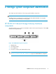
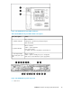
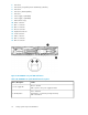
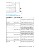

2. PCIe slot 6
3. PCIe slot 4 (occupied by P812 Smart Array controller)
4. PCIe slot 2
5. PCIe slot 3 (SAS Expander)
6. PCIe slot 1
7. Power supply 2 (standard)
8. Power supply 1 (standard)
9. USB connectors (2)
10. Video connector
11. NIC 1 connector
12. NIC 2 connector
13. Mouse connector
14. Keyboard connector
15. Serial connector
16. iLO 3 connector
17. NIC 3 connector
18. NIC 4 connector
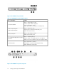
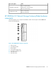
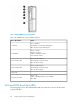
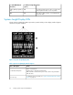
Figure 8 HP X3800 G2 rear panel LEDs and buttons
.
Table 5 HP X3800 G2 rear panel LED and button descriptions
StatusItem / Description
Green = Normal
Off = System is off or power supply has failed
1. Power supply LED
Blue = Activated
Flashing blue = System being managed remotely
Off = Deactivated
2. UID LED/button
Storage system component identification26