HP StorageWorks Modular Smart Array 500 System Maintenance and Service Guide (formerly Smart Array Cluster Storage System) October 2003 (Fourth Edition) Part Number 251850-004 HP CONFIDENTIAL Codename: Aurora Part Number: 251850-004 Last Saved On: 9/19/03 10:52 AM
© 2002, 2003 Hewlett-Packard Development Company, L.P. Microsoft®, Windows®, and Windows NT® are trademarks of Microsoft Corporation in the U.S. and other countries. Hewlett-Packard Company shall not be liable for technical or editorial errors or omissions contained herein. The information in this document is provided “as is” without warranty of any kind and is subject to change without notice.
Contents About This Guide Audience Assumptions..................................................................................................................................v Technician Notes...........................................................................................................................................v Where to Go for Additional Help.................................................................................................................vi Telephone Numbers ...........
Contents Chapter 4 Component Identification Front Panel Components............................................................................................................................4-1 Enclosure LEDs .........................................................................................................................................4-2 Rear Panel Components.............................................................................................................................
About This Guide This maintenance and service guide can be used for reference when servicing the HP StorageWorks Modular Smart Array 500 system. WARNING: To reduce the risk of personal injury from electric shock and hazardous energy levels, only authorized service technicians should attempt to repair this equipment. Improper repairs can create conditions that are hazardous. Audience Assumptions This guide is for service technicians.
About This Guide CAUTION: To properly ventilate the system, you must provide at least 7.6 cm (3.0 in) of clearance at the front and back of the system. CAUTION: The equipment is designed to be electrically grounded (earthed). To ensure proper operation, plug the AC power cord into a properly grounded AC outlet only. NOTE: Any indications of component replacement or printed wiring board modifications may void any warranty.
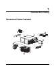
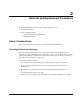
1 Illustrated Parts Catalog Mechanical and System Components 6 7 1 3 8 5 2 4 HP StorageWorks Modular Smart Array 500 System Maintenance and Service Guide HP CONFIDENTIAL Codename: Aurora Part Number: 251850-004 Last Saved On: 9/19/03 10:55 AM 1-1
Illustrated Parts Catalog Table 1-1: Mechanical and System Components Item Description Spare Part Number Mechanical Components 1 Chassis, 4U, with backplane 229198-001 2 Bezel blank 229208-001 3 Interconnect blank 229200-001 System Components 4 AC power supply assembly, 499 W 212398-001 5 Blower 123482-001 Boards 6 2-Port Shared Storage Module for HP StorageWorks Modular Smart Array 500 system 229205-001 7 Controller 229202-001 8 Power button/LED assembly 229201-001 9 Cache modu
2 Removal and Replacement Procedures To service the MSA500 system, you may need the following tools: • Flat-blade screwdriver • From the SmartStart CD: — Advanced Diagnostics Utility (ADU) — ROM Update Utility Safety Considerations Before performing service procedures, review all the safety information. Preventing Electrostatic Discharge To prevent damaging the system, be aware of the precautions you need to follow when setting up the system or handling parts.
Removal and Replacement Procedures Rack Warnings and Cautions WARNING: Because the rack allows stacking of computer components on a vertical rather than horizontal plane, be sure that precautions have been taken to provide for rack stability and safety. It is important to follow these precautions providing for rack stability and safety, and to protect both personnel and property. Heed all cautions and warnings throughout the installation instructions provided with the device.
Removal and Replacement Procedures WARNING: Be sure that the AC power supply branch circuit that provides power to the rack is not overloaded. Not overloading AC power to the rack power supply circuit reduces the risk of personal injury, fire, or damage to the equipment. The total rack load should not exceed 80 percent of the branch circuit rating. Consult the electrical authority having jurisdiction over your facility wiring and installation requirements.
Removal and Replacement Procedures System Power Down WARNING: To reduce the risk of personal injury, electric shock, or damage to the equipment, remove the power cord to remove power from the system. The front panel Power On/Standby button does not completely shut off system power. Portions of the power supply and some internal circuitry remain active until AC power is removed. IMPORTANT: If installing a hot-plug device, it is not necessary to power down the system. To power down the system: 1.
Removal and Replacement Procedures Hot-Plug SCSI Hard Drive CAUTION: If you must replace a hot-plug drive, follow the guidelines in this section. Failure to do so can result in data loss and can void the warranty. RAID 0 is not a fault-tolerant configuration. Never remove a drive from a RAID 0 array unless it has failed. Drive failure is indicated by an amber drive failure LED. In a RAID 0 configuration, removal of an operating drive results in data loss.
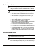
Removal and Replacement Procedures To remove the component: 1. Be sure that the online and activity LEDs on the failed drive are both off. CAUTION: To prevent improper cooling and thermal damage, do not operate the system unless all bays are populated with either a component or a blank. 2. Remove the failed drive. 3 2 1 To replace a hot-plug SCSI hard drive: 1. Slide the drive into the bay until it locks into place. 2. Close the lever. CAUTION: Data loss can occur if the drive is not firmly seated. 3.
Removal and Replacement Procedures Universal Hot-Plug Tape Drive To remove the component: CAUTION: To prevent improper cooling and thermal damage, do not operate the system unless all bays are populated with either a component or a blank. CAUTION: Installation of the tape drive height converter is permanent. Attempting to remove the converter after installation voids the tape drive warranty. 1 2 To replace the Universal Hot-Plug Tape drive: 1.
Removal and Replacement Procedures Bezel Blank To remove the component: CAUTION: Always populate bays with either a component or blank. Proper airflow can only be maintained when the bays are populated. Operating the system with unpopulated bays can lead to improper cooling and thermal damage. 1 2 3 To replace the bezel blank: 1. Slide the bezel blank into the bay until it locks into place. 2. Close the lever.
Removal and Replacement Procedures HP StorageWorks Modular Smart Array 500 Controller When the MSA500 controller in a single-controller system fails, HP recommends that you migrate the cache module to a new controller. Battery-backed cached data in a failed controller can remain intact for up to 3 days with 256-MB modules or up to 4 days with 128-MB modules.
Removal and Replacement Procedures Battery-Backed Cache Module CAUTION: To prevent data loss or equipment damage, follow the instructions in this procedure. To remove the component: 1. Determine if the controller configuration supports hot-plug cache replacement: — If the system is equipped with a single controller, power down the system before performing step 2. Refer to “System Power Down” in this chapter.
Removal and Replacement Procedures Blower To remove the component: WARNING: The blower blades rotate at a high speed. Avoid touching the rotating blades when removing the blower. NOTE: The power supply is designed so that removing a blower does not adversely affect system performance. However, do not remove a blower until the replacement blower is available. 1 2 1 To replace the blower: 1. Align the guidepost on the blower with the connector on the power supply.
Removal and Replacement Procedures Hot-Plug Power Supply Observe the following cautions for AC power supplies: CAUTION: Removing a power supply significantly changes the airflow within the enclosure. The system will shut down to prevent overheating unless the power supply is replaced within 5 minutes. CAUTION: Handle the blower carefully to avoid damaging the housing. • Do not press on the center section of the blower because this action can damage the blades. Press only on the outer edge of the blower.
Removal and Replacement Procedures To remove the component: 1. Disconnect the power cord from the power supply. 2. Remove the blower. Refer to “Blower” in this chapter. 3. Remove the power supply. 1 2 To replace the power supply: 1. Lift the locking latch. 2. Slide the power supply into the bay until it locks into place. 3. Install the blower on the power supply. 4. Connect the power cord.
Removal and Replacement Procedures 2-Port and 4-Port Shared Storage Modules To remove the component: 1. Power down the system. Refer to “System Power Down” in this chapter. 2. Disconnect the SCSI cabling connected to the 2-Port Ultra3 SCSI I/O module. 3. Remove the module. 1 2 To replace the component, reverse the removal procedure.
Removal and Replacement Procedures Interconnect Blank To remove the component: CAUTION: Always populate interconnect bays with a blank. Proper airflow can only be maintained when the bays are populated. Operating the system with unpopulated bays can lead to improper cooling and thermal damage. 1 2 To replace the component, reverse the removal procedure.
Removal and Replacement Procedures Power Button/LED Assembly To remove the component: 1. Power down the system. Refer to “System Power Down” in this chapter. 2. Remove the hot-plug SCSI hard drives in bays 10 through 14. Refer to “Hot-Plug SCSI Hard Drive” in this chapter. IMPORTANT: To press the plastic latches behind the front bezel, you may choose to use a flat-head screwdriver. 3.
Removal and Replacement Procedures MSA500 System Chassis and Backplane If the backplane board fails or the chassis sustains significant damage, you must order a replacement chassis. To replace the chassis and backplane: 1. Power down the system. Refer to “System Power Down” in this chapter. 2. Remove all installed hard drive blanks. Refer to “Hard Drive Blank” in this chapter. 3. Remove all installed hot-plug SCSI hard drives. Refer to “Hot-Plug SCSI Hard Drive” in this chapter. 4.
3 Diagnostic Tools Server Utilities HP utilities provide reporting functions that enable event-focused management and diagnostics. To install and run these utilities, refer to the server documentation. • Diagnostics Utility—This utility tests and verifies proper operation of the system hardware. If problems are found, the utility isolates failure(s) down to the replaceable part, whenever possible. When an operating system is installed with SmartStart Version 5.
Diagnostic Tools ROM Upgrades Each MSA500 controller has a ROM that contains the controller firmware. The ROM flash tool enables system administrators to efficiently upgrade array controller ROM images. This tool has the following features: • Supports Microsoft Windows NT® 4.
Diagnostic Tools NetWare Online Array Configuration Utility (CPQONLIN) The NetWare Online Array Configuration Utility, also called CPQONLIN, is a NetWare Loadable Module (NLM) for configuring drive arrays without shutting down the server. CPQONLIN also provides information about the status of drives attached to the MSA500 controller. It indicates drive failure, expansion, or waiting for expansion or rebuild (queued).
4 Component Identification Front Panel Components 1 2 3 7 4 6 5 Table 4-1: Front Panel Components Item Description 1 Bezel blank (bay for optional redundant controller) 2 Service port (for HP service technicians only) 3 Hot-plug MSA500 controller 4 Controller display 5 Power On/Standby button 6 Enclosure LEDs (refer to Table 4-2) 7 Hot-plug SCSI hard drive bays with blanks HP StorageWorks Modular Smart Array 500 System Maintenance and Service Guide HP CONFIDENTIAL Codename: Aurora P
Component Identification Enclosure LEDs 1 2 3 Table 4-2: Enclosure LEDs Item LED Description Status 1 Environmental Monitoring Unit (EMU) heartbeat Green flashing = Shared storage module is operating normally. System power Green = System power is On. 2 Green/Off = Shared storage module is not operating normally. Off = System is in standby mode or power is removed from the system.
Component Identification Rear Panel Components 1 4 2 3 Table 4-3: Rear Panel Components Item Description 1 Interconnect blanks (Required for proper airflow) 2 Power supply/blower assemblies 3 AC power connectors 4 2-Port Shared Storage Module Power Supply/Blower Assembly LEDs The power supply/blower assembly LEDs have the following functions: • Green—The power supply is receiving power, and the blower is operating normally.
Component Identification 2-Port Shared Storage Module Components 1 2 Table 4-4: 2-Port Shared Storage Module Components 4-4 Item Connector Description Bus 1 SCSI port connector A 2 SCSI port connector B HP StorageWorks Modular Smart Array 500 System Maintenance and Service Guide HP CONFIDENTIAL Codename: Aurora Part Number: 251850-004 Last Saved On: 9/19/03 11:00 AM
Component Identification 2-Port Shared Storage Module LEDs 1 2 3 Table 4-5: 2-Port Shared Storage Module LEDs Item LED Description Status 1 Power Green = Power on Off = Power off 2 SCSI host port A Flashing green = On/Activity 3 SCSI host port B Off = Off HP StorageWorks Modular Smart Array 500 System Maintenance and Service Guide HP CONFIDENTIAL Codename: Aurora Part Number: 251850-004 Last Saved On: 9/19/03 11:00 AM 4-5
Component Identification 4-Port Shared Storage Module Components 1 2 3 4 Table 4-6: 4-Port Shared Storage Module Components 4-6 Item Connector Description Bus 1 SCSI port connector A1 A 2 SCSI port connector A2 3 SCSI port connector B1 4 SCSI port connector B2 B HP StorageWorks Modular Smart Array 500 System Maintenance and Service Guide HP CONFIDENTIAL Codename: Aurora Part Number: 251850-004 Last Saved On: 9/19/03 11:00 AM
Component Identification 4-Port Shared Storage Module LEDs 1 2 3 Table 4-7: 4-Port Shared Storage Module LEDs Item LED Description Status 1 Power Green = Power on Off = Power off 2 SCSI host port A connectors 1 and 2 3 SCSI host port B connectors 1 and 2 Flashing green = On/Activity Off = Off HP StorageWorks Modular Smart Array 500 System Maintenance and Service Guide HP CONFIDENTIAL Codename: Aurora Part Number: 251850-004 Last Saved On: 9/19/03 11:00 AM 4-7
Component Identification Controller Components Controller Display Each MSA500 controller has an LCD display for informational and error messages.
Component Identification Controller LEDs 15 14 13 12 11 10 9 8 17 7 6 5 4 3 2 1 0 16 Table 4-9: Controller LEDs Item LED Description Status 0-2 Busy status Green = Controller is idle. Off = Controller is operating at full capacity.
Component Identification Table 4-9: Controller LEDs continued Item LED Description Status 14 Cache activity Green = Cache activity Off = No cache activity Flashing green = Cache transfer pending 15 Drive failure Green = An array-configured drive has failed. Off = No drive failures 16 Active redundancy Green = Controllers are operating with redundancy. Off = No redundancy 17 Fault Amber = Error message received by controller display.
Component Identification SCSI IDs 1 2 3 4 5 6 7 8 9 10 11 12 13 14 Table 4-10: SCSI IDs Bay SCSI ID Bus Port 1 0 0 2 1 3 2 4 3 5 4 6 5 7 8 8 0 9 1 10 2 11 3 12 4 13 5 14 8 1 HP StorageWorks Modular Smart Array 500 System Maintenance and Service Guide HP CONFIDENTIAL Codename: Aurora Part Number: 251850-004 Last Saved On: 9/19/03 11:00 AM 4-11
Component Identification Hot-Plug SCSI Hard Drive LEDs 1 3 2 Table 4-11: Hot-Plug SCSI Hard Drive LEDs Item LED Description 1 Activity 2 Online 3 Fault Hot-Plug SCSI Hard Drive LED Combinations Table 4-12: Hot-Plug SCSI Hard Drive LED Combinations Activity LED Online LED Fault LED Status On Flashing Off Do not remove the drive.
5 Specifications System Unit Specification Table 5-1: System Unit Specifications Specification Value Dimensions Height 17.5 cm (6.9 in) Depth 52.1 cm (20.5 in) Width 48.3 cm (19.0 in) Weight, no drives installed 22.7 kg (50 lb) Input power requirements * (US and international) Rated input voltage 100 to 240 VAC Rated input frequency 50 to 60 Hz Rated input current 7.
Specifications Table 5-1: System Unit Specifications continued Specification Value Relative humidity (noncondensing) Operating 10% to 90% Nonoperating up to 95% Maximum wet bulb temperature Long-term storage 29°C (84.2°F) Short term storage 30°C (86°F) Memory Table 5-2: SDRAM DIMM Specifications Specification Value Speed 100 MHz minimum Width 80 bits Note: Use only HP battery-backed cache modules.
Specifications Hot-Plug AC Power Supply Table 5-4: Hot-Plug Power Supply Specifications Specification Value Height 12.7 cm (4.5 in) Width 15.9 cm (6.25 in) Depth 24.1 cm (9.5 in) Weight 2.9 kg (6.4 lb) Note: The MSA500 system power supply specifications are calculated without the blower.
Index Symbols and Numbers 2-Port Shared Storage Module components 4-4 LEDs 4-5 location 4-3 removing 2-14 replacing 2-14 spare part number 1-2 4-Port Shared Storage Module components 4-6 LEDs 4-7 removing 2-14 replacing 2-14 spare part number 1-2 A AC power connectors 4-3 AC power cord, spare part number 1-2 ADU See Array Diagnostics Utility (ADU) Array Configuration Utility (ACU) features 3-2 version 3-2 array controllers LEDs 4-9 MSA500 4-1 removing 2-9 replacing 2-9 spare part number 1-2 Array Diagnost
Index drives See hot-plug SCSI hard drives; tape drives fault 4-10, 4-12 fault, enclosure 4-2 hot-plug SCSI hard drives 4-12 power supply/blower assembly 4-3 system power 4-2 E EMU heartbeat LED 4-2 enclosure LEDs 4-1, 4-2 M F G mechanical components 1-2 modules See 2-Port Shared Storage Module; 4-Port Shared Storage Module; battery-backed cache module M-Series Rack Rail option, spare part number 1-2 grounding vi grounding plug v P fault LEDs 4-2, 4-10, 4-12 front panel components 4-1 ports H ha
Index backplane 2-17 battery-backed cache module 2-10 bezel blank 2-8 blower 2-11 chassis 2-17 hard drive blank 2-4 hot-plug SCSI hard drives 2-6 interconnect blank 2-15 power button/LED assembly 2-16 power supplies 2-13 tape drives 2-7 restoring data 2-9 return kit, spare part number 1-2 S SCSI IDs 4-11 service port 4-1 shared storage modules See 2-Port Shared Storage Module; 4-Port Shared Storage Module SmartStart CD 2-1, 3-2 spare part numbers 2-Port Shared Storage Module 1-2 4-Port Shared Storage Modu