
Specifications


Table Of Contents
- MSA1510i maintenance and service guide
- Contents
- About this guide
- 1 Illustrated parts list
- 2 Specifications
- 3 System components and LEDs
- 4 Available diagnostic tools
- 5 Customer replaceable components
- Procedural overview
- Customer self repair
- Recommended tools
- Warnings and precautions
- Determining whether a component is hot-pluggable
- Powering off and powering on the MSA
- Removing or installing a 2-Port Ethernet iSCSI blank
- Removing or installing a hard drive blank
- Replacing a hard drive
- Replacing the controller, controller cache, or controller battery
- Replacing a 2-Port Ethernet iSCSI module
- Replacing a fan module
- Replacing a SCSI I/O module
- Replacing a power supply module
- Replacing the MSA1510i chassis
- A Regulatory compliance and safety
- Index
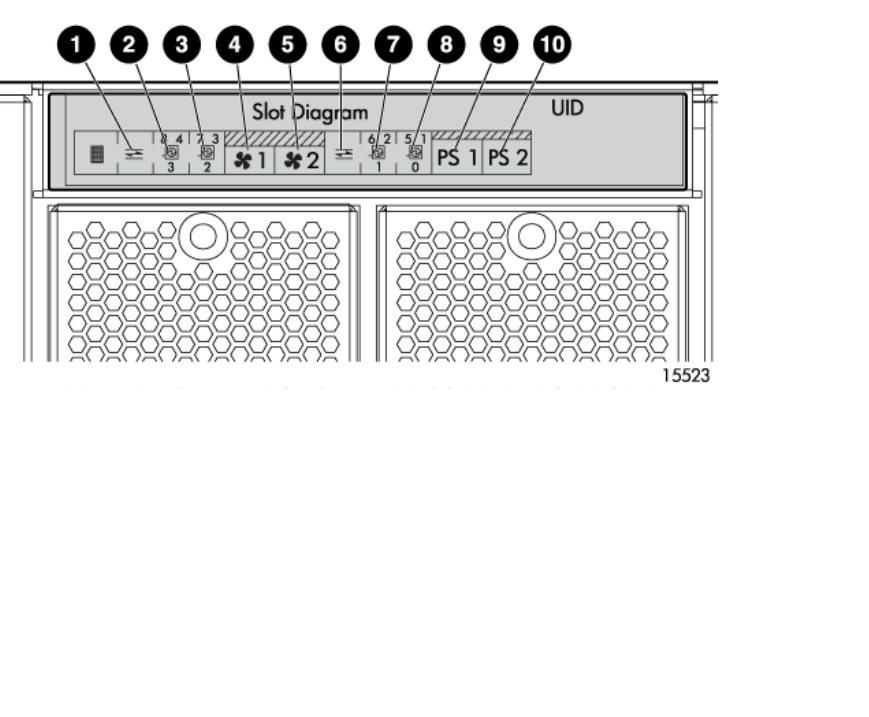
Slot diagram LE
Ds
Located on the r
ear of the MSA, the slot diagram provides information about MSA modules.
1. 2 – Po r t E
thernet iSCSI module (for the controller in slot 2)
2. SCSI I/O module (bus 3)
3. SCSI I/O module (bus 2)
4. Fan module 1
5. Fan module 2
6. 2–Port Ethernet iSCSI module (for the controller in slot 2)
7. S C S I I / O
module (bus 1)
8. SCSI I/O module (bus 0)
9. Power supply 1
10. Power
supply 2
newpage p
i
24
System components and LEDs