
Specifications


Table Of Contents
- MSA1510i maintenance and service guide
- Contents
- About this guide
- 1 Illustrated parts list
- 2 Specifications
- 3 System components and LEDs
- 4 Available diagnostic tools
- 5 Customer replaceable components
- Procedural overview
- Customer self repair
- Recommended tools
- Warnings and precautions
- Determining whether a component is hot-pluggable
- Powering off and powering on the MSA
- Removing or installing a 2-Port Ethernet iSCSI blank
- Removing or installing a hard drive blank
- Replacing a hard drive
- Replacing the controller, controller cache, or controller battery
- Replacing a 2-Port Ethernet iSCSI module
- Replacing a fan module
- Replacing a SCSI I/O module
- Replacing a power supply module
- Replacing the MSA1510i chassis
- A Regulatory compliance and safety
- Index
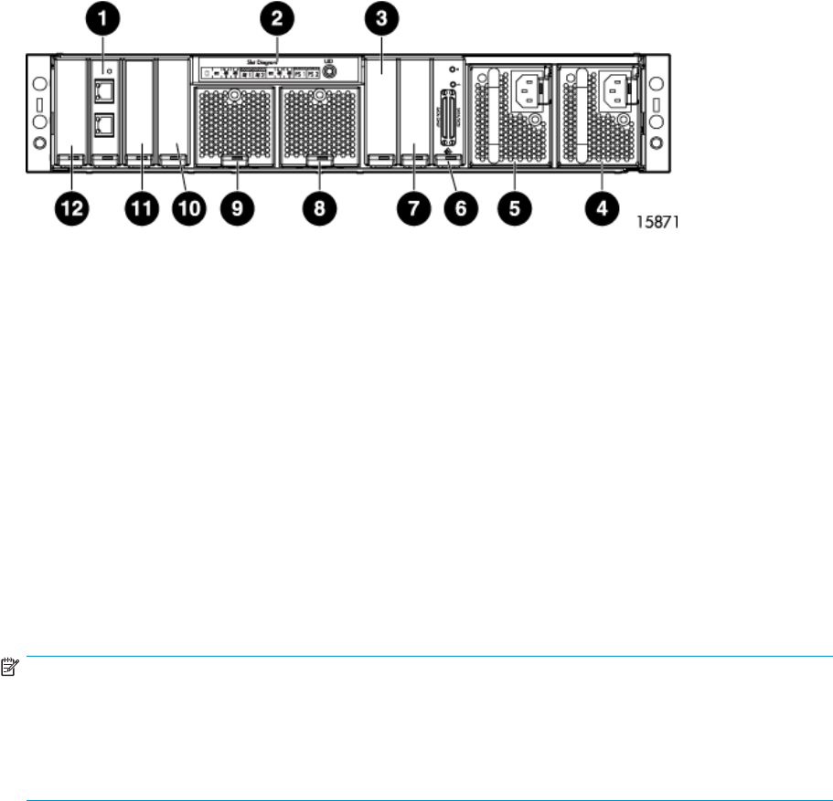
Rear view
1. 2–Port Ethernet iSCSI module (for the controller in slot 1)
2. Chassis slot diagram
3. Blank for
additional 2-Port Ethernet iSCSI module (for the controller in slot 2)
4. Power supply module 2
5. Power supply module 1
6. SCSI I/O m
odule (bus 0)
7. Blank for additional SCSI I/O module (bus 1)
8. Fan module 2
9. Fan modu
le 1
10. Blank for additional SCSI I/O module (bus 2)
11. Blank for additional SCSI I/O module (bus 3)
12. U nu se d s l ot
NOTE:
Each MSA SCSI I/O module has two ports. Depending on the type of external hard drive storage
enclosure, one or both of the ports may be used.
• When connecting SATA enclosures, both ports may be used.
• WhenconnectingSCSIenclosures,onlytherightportmaybeused.
newpage pi
18
System components and LEDs