
Specifications


Table Of Contents
- MSA1510i maintenance and service guide
- Contents
- About this guide
- 1 Illustrated parts list
- 2 Specifications
- 3 System components and LEDs
- 4 Available diagnostic tools
- 5 Customer replaceable components
- Procedural overview
- Customer self repair
- Recommended tools
- Warnings and precautions
- Determining whether a component is hot-pluggable
- Powering off and powering on the MSA
- Removing or installing a 2-Port Ethernet iSCSI blank
- Removing or installing a hard drive blank
- Replacing a hard drive
- Replacing the controller, controller cache, or controller battery
- Replacing a 2-Port Ethernet iSCSI module
- Replacing a fan module
- Replacing a SCSI I/O module
- Replacing a power supply module
- Replacing the MSA1510i chassis
- A Regulatory compliance and safety
- Index
3 System components and LEDs
This chapter includes fi gures and tables that identify system components and describe chassis and
module LEDs patterns.
•Frontview
•Rearview
• Chassis and component LEDs
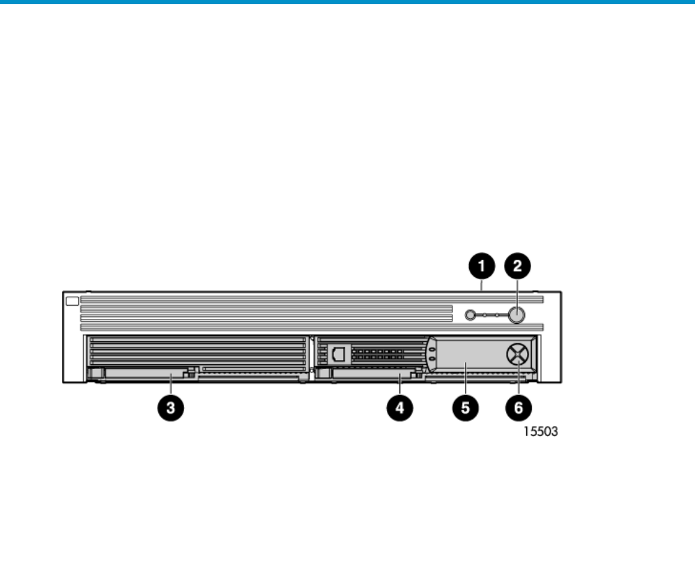
Front view
1. Chassis LEDs
2. Chassis Power On/Standby button
3. Blank for an additional controller (controller slot 2)
4. MSA1510i controller (controller slot 1)
5. Controller LCD message display panel
6. Controller LCD panel push buttons
1510i Modular Smart Array maintenance and service guide
17