HP Server tc2110 Operations and Maintenance Guide Online Version: 1.
Notice The information contained in this document is subject to change without notice. Hewlett-Packard makes no warranty of any kind with regard to this material, including, but not limited to, the implied warranties of merchantability and fitness for a particular purpose. HewlettPackard shall not be liable for errors contained herein or for incidental or consequential damages in connection with the furnishing, performance, or use of this material.
Contents 1 Controls and Indicators ......................................................................................................................... 1 Front Panel ............................................................................................................................................... 1 Additional Controls and Indicators........................................................................................................ 2 Rear Panel ...........................................
Contents IRQ Settings ....................................................................................................................................... 37 Boot Priority ........................................................................................................................................ 37 Installing an Accessory Board ............................................................................................................ 38 Removing Accessory Boards ............................
Contents Server stops working (hangs)...............................................................Error! Bookmark not defined. Power Problems........................................................................................Error! Bookmark not defined. Video/Monitor Problems ...........................................................................Error! Bookmark not defined. Configuration Problems ............................................................................
Contents 8 Parts Identification ............................................................................................................................... 97 Exploded View – Covers and Bezels...................................................................................................... 97 Exploded View – Mass Storage Devices ................................................................................................ 98 Exploded View – Chassis Fan, Power Supply, and System Board.............
1 Controls and Indicators This chapter describes the controls, ports, and indicators on the front and rear of the HP Server tc2110. Front Panel The front panel provides the controls and indicators commonly used when operating the Server. Figure 1-1.
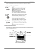
Chapter 1 Controls and Indicators Table 1-1 provides the front panel power switch and the lower bezel LED indicator definitions. Table 1-1. Control Panel Switch and Indicators Control / Indicator Description Power On/Off/ Sleep LED This green LED indicator provides the power state of the Server: Steady green when the Server is operating normally. Blinking green when the Server is in standby mode. Off when the Server is powered off.
Chapter 1 NOTE Controls and Indicators For more information on the HP Tape Drive and its error codes, refer to the documentation provided with the tape drive or refer to Hewlett-Packard’s web site, at: http://www.hp.com/. Rear Panel The ports, connectors, switches and other related items at the rear of the Server are listed below and shown in Figure 1-3. · The power connector accepts a standard power cable to connect the HP Server tc2110 with the site power source.
Chapter 1 Controls and Indicators Figure 1-3. Rear Panel and Ports Applying Power to the HP Server If you choose to use sleep states in conjunction with the HP Server tc2110, refer to “Sleep States (ACPI)” later in this section and your respective NOS. Connecting the Power Cords WARNING 4 For your safety always connect equipment to a grounded wall outlet.
Chapter 1 Controls and Indicators Setting the input voltage Remove the warning label covering the power connector, and ensure that the voltage setting is correct for your country. (The voltage is set during manufacture and should already be correct.) Figure 1-4. Input Voltage Selection Switch Connecting the Power Cords 1. Connect the power cords to the rear of the monitor and the HP Server. (The connectors are shaped to go in one way only.) 2.
Chapter 1 Controls and Indicators Powering-Down the Server 1. Make sure that you have exited all applications. 2. Use the shut down command in your operating system’s Start menu (for Windows NT 4.0 and Windows 2000, and Windows XP operating systems). 3. When prompted, press the power button on the HP Server. WARNING The power supply will continue to provide standby current to the Server until the power cord is disconnected from the rear panel.
Chapter 1 Controls and Indicators the user interface provided by the ACPI-compliant NOS. While power management is under the control of the ACPI-compliant NOS, the HP Server’s power button is capable of an override in case of a non-responsive NOS. NOTE The HP Server power button will force a power down without waiting for the NOS to gracefully shut down the Server, if the power button is pressed and held for more than five seconds.
2 External Connectors Unless otherwise noted, the following features apply to all models. Some features are factory installed; others are optional.
Chapter 2 External Connectors Parallel Port Connector 1 2 3 4 5 6 7 8 9 10 11 12 13 14 15 16 17 18 19 20 21 22 23 24 25 Parallel Connector Parallel Port Connector (female) Pinouts Pin Number Signal Description Pin Number Signal Description 1 Strobe5 10 Acknowledgeb 2 Data bit 06 11 Busy 3 Data bit 1a 12 Paper end 4 Data bit 2a 13 Select 5 Data bit 3a 14 Auto line feedb 6 Data bit 4a 15 Error1 7 Data bit 5a 16 Initialize printerb 8 Data bit 6a 17 Select inb 9 Data bit
Chapter 2 External Connectors 68-Pin LVD SCSI Port Connector (Low Voltage Differential) Pin 1 LVD SCSI Connector (Male) Pin 68 68-Pin SCSI Port Connector Shown as pin matching Pin Number Signal Description Pin Number Signal Description 1 +DB(12) 35 -DB(12) 2 +DB(13) 36 -DB(13) 3 +DB(14) 37 -DB(14) 4 +DB(15) 38 -DB(15) 5 +DB(P1) 39 -DB(P1) 6 +DB(0) 40 -DB(0) 7 +DB(1) 41 -DB(1) 8 +DB(2) 42 -DB(2) 9 +DB(3) 43 -DB(3) 10 +DB(4) 44 -DB(4) 11 +DB(5) 45 -DB(5) 12
Chapter 2 External Connectors Pin Number 34 Signal Description +DB(11) Pin Number Signal Description 68 -DB(11) 50-Pin Narrow SCSI Port Connector – Accessory Board Position 25 Position 1 Position 50 Position 26 SCSI Port Connector 50-Pin Narrow SCSI Port Connector Pinouts Pin Number Signal Description Pin Number Signal Description 1-11 Ground 37 Reserved 12 Reserved 38 Termpwr 13 Open 39 Reserved 14 Reserved 40 Ground 15-25 Ground 41 -ATN 26 -DB(0) 42 Ground 27 -DB(1
Chapter 2 External Connectors Standard LAN Connector LAN Connector LAN Connector Pinouts Pin Number Signal Description 1 Data signal 2 Not used 3 Ground 4 Power (+5 V dc) 5 Clock signal 6-8 Not used 13
3 Installing and Configuring Opening and Closing the HP Server This section describes how to remove and replace the left side cover and the upper front bezel of the HP Server tc2110. WARNING Before removing the cover, always disconnect the power cord and unplug telephone cables. Disconnect the power cord to avoid exposure to high energy levels that may cause burns when parts are short-circuited by metal objects such as tools or jewelry.
Chapter 3 Installing and Configuring 3. Pull outward on the latch, grasp the edges of the cover and lift the cover upward to remove it. See Figure 3-1. Figure 3-1. Removing the Left Side Cover 4. Place the left side cover in a safe place for re-installation later. WARNING Parts inside the server may be hot; wait for them to cool before touching them. Replacing the Left Side Cover To replace the left side cover, follow these steps: 1.
Chapter 3 Installing and Configuring 4. Lift the latch to engage the lock and completely close the side cover. The side cover should snap into place when securely closed. Figure 3-2. Replacing the Left Side Cover 5. Lock the cover using the key provided, if required. Reconnect all the power and telecommunication cables. Removing the Upper Bezel The upper front bezel must be removed to install or replace mass storage devices in the first four shelves (common trays). To remove the upper bezel: 1.
Chapter 3 Installing and Configuring Figure 3-3. Removing the Upper Front Bezel Replacing the Upper Bezel 1. Hold the upper bezel next to the chassis, and align the hinge teeth, both upper and lower, as shown in the following illustration. The hinge teeth can only fit together within the space allowed, so it should fit on the first try. 2. Close the upper bezel, swinging it to the left, where it will engage the release tabs. 3. Push the upper bezel closed so it engages the release tabs.
Chapter 3 Installing and Configuring Figure 3-4. Replacing the Upper Bezel Mass Storage This section describes how to install the internal mass storage devices, including the internal hard disk drives (IDE or SCSI) and the optional tape backup (DAT) drive. The HP Server tc2110 comes standard with one flexible disk drive, one IDE CD-ROM, and at least one SCSI or IDE hard disk drive, depending on the model. The mass storage cage can hold two hard disk drives.
Chapter 3 Installing and Configuring Figure 3-5. Mass Storage Locations Mass Storage Guidelines · General Guidelines o Use care when unpacking and handling the hard disk drives. The hard disk drives are very susceptible to mechanical shock and can be easily damaged by a drop as short as one-quarter of an inch. If the drop would crack an egg, it will damage the drive. o Do not stack drives. o The Server is internally limited to 6 mass storage shelves.
Chapter 3 Installing and Configuring o Ensure that the SCSI devices you install do not have terminations installed. The SCSI drives are connected to a terminated cable and do not require termination on the SCSI drive. o Use only HP Ultra 160 SCSI LVD (1-inch) low profile 3.5-inch hard disk drives for the hard disk drive cage. o The optional HP backup tape drive comes with a 50-to-68-pin adapter to connect to the 68-pin SCSI connector on the SCSI cable used for connection of backup tape drive.
Chapter 3 Installing and Configuring The IDE Server model uses the IDE-1 for the boot drive and the IDE-2 connector for the IDE CD-ROM. The Setup Utility (BIOS) can be used to change the boot order of the flexible disk drive and the IDE devices. Refer to “BIOS Setup Utility” later in this chapter for more information. IDE Mass Storage Additions Table 3-1 lists the number and types of mass storage devices that may be added to the IDE model of the HP Server. Table 3-1.
Chapter 3 Installing and Configuring The HP Server tc2110 will support an HP NetRAID 1M controller board, separate from the SCSI controller board. SCSI Mass Storage Additions Table 3-2 lists the number and types of mass storage devices that may be added to the SCSI model of the HP Server. Table 3-2. SCSI Model Mass Storage Devices Interface Types Max No.
Chapter 3 Installing and Configuring Figure 3-6. Releasing the Retaining Clips 5. Remove the hard disk drive from its protective bag and check, or set the following items: a. Check for bent pins on any of the connectors and carefully straighten any bent pins. b. If mounting a SCSI hard drive, ensure it is not terminated and set the SCSI ID jumper for address = ID 1. Refer to the documentation provided with the hard drive. 6.
Chapter 3 Installing and Configuring 7. Slide the drive into the lower cage opening with the data and power connectors facing out of the drive cage. See Figure 3-8. Figure 3-8. Drive Cage Mounting 8. Attach the data connectors to the drives. Assuming that you want to boot from the original hard drive, attached the end connector (marked DRIVE 0) to this drive and the other connectors to the remaining drive(s). If mounting a SCSI hard drive, connect the SCSI cable to both drives. 9.
Chapter 3 Installing and Configuring NOTE If the hard disk drive (HDD) you are planning to install already has a mounting tray attached, you must remove it from the tray. 6. Install the hard disk drive as described below: a. Place the hard disk drive into the tray and use the screws provided to secure it to the tray from the bottom. b. Insert the hard disk drive assembly into the fourth shelf. See Figure 3-9. The tabs should snap into place when the drive is pushed all the way into the fourth shelf.
Chapter 3 Installing and Configuring 1. If the Server is operating, power down the Server. Refer to Chapter 1, “Controls and Indicators” for instructions. 2. Disconnect the power cord and any external cables connected to the Server. If necessary, label each one to expedite re-assembly. 3. Remove the left side cover. Refer to “Opening and Closing the HP Server” earlier in this chapter. 4. Remove the upper bezel. Refer to “Opening and Closing the HP Server” earlier in this chapter. 5.
Chapter 3 Installing and Configuring Installing an Optional Backup Tape Drive The optional HP SureStore DAT 24i backup tape drive is a single-ended device and may slow down the disk access time for the Ultra-160 SCSI drives. A second SCSI controller board may be required to separately control the backup tape drive. 1. If the Server is already installed and operating, power-down the Server. Refer to Chapter 1, “Controls and Indicators.” 2.
Chapter 3 Installing and Configuring Figure 3-11. Installing the Optional Backup Tape Drive Memory Modules The main memory for the HP Tower Server tc2110 is implemented using three memory slots on the system board and it supports up to 1.5 GB (512 MB x 3) of memory. The Server only supports HP 168-pin, PC 133 (133 MHz), 3.3V, unbuffered, ECC SDRAM DIMMs and ships with at least one 128 MB DIMM installed. NOTE Use only memory modules provided for your HP Server model.
Chapter 3 Installing and Configuring · Supported memory capacity ranges from 128 MB to 1.5 GB maximum (512 MB x 3 DIMM slots total). The minimum capacity is 128 MB (one DIMM). · DIMM sizes may be mixed on the system board and may be loaded in any order (1 through 3). However, HP recommends starting at slot 1 and filling the slots in order with the largest size first: 1, 2, and 3. · Open slots between DIMMs are permitted. · When handling DIMMs, observe anti-static precautions to avoid damage.
Chapter 3 Installing and Configuring Figure 3-12. DIMM Locations on System Board 6. Remove the new DIMM from its container, handling the module by its edges. Use only HP PC133 (133 MHz) unbuffered ECC SDRAM DIMMs. CAUTION The DIMM should be left in the anti-static container or placed on an anti-static surface, until you are ready to install it into the DIMM slot. 7. Spread the two retaining latches on the slot and align the notches on the DIMM with the keys on the slot. See Figure 3-13. Figure 3-13.
Chapter 3 Installing and Configuring Figure 3-14. DIMM Insertion 9. Repeat Steps 7-8 to install the remaining DIMMs of your memory configuration. Removing DIMMs You may need to remove a DIMM module to downsize your memory configuration or to replace a defective DIMM. 1. If the Server is already installed and working, power down the Server. Refer to Chapter 1, “Controls and Indicators.” 2. Disconnect the power cables and all external cables. If necessary, label each one to support re-assembly.
Chapter 3 Installing and Configuring CAUTION Wear a wrist-strap and use a static-dissipating work surface connected to the chassis when handling components. Ensure the metal of the wrist-strap contacts your skin. Removing the Heat Sink and Cooling Fan 1. If the Server is operating, power down the Server. Refer to Chapter 1, “Controls and Indicators” for instructions. 2. Disconnect the power cord and any external cables connected to the Server. If necessary, label each one to expedite re-assembly.
Chapter 3 Installing and Configuring Removing the Processor 1. If you have not removed the heat sink-cooling fan assembly, do so now before continuing. CAUTION Wear a wrist-strap and use a static-dissipating work surface connected to the chassis when handling components. Ensure the metal of the wrist-strap contacts your skin 2. Open the ZIF (Zero Insertion Force) lever completely to allow removal of the processor. Figure 3-16. Removing the Processor 3.
Chapter 3 Installing and Configuring 4. Insert the processor into the socket and close the ZIF lever to fully seat the processor. You should hear the ZIF lever click when it closes properly. Figure 3-17. Replacing the Processor Replacing the Heat Sink and Cooling Fan Once the processor is installed, the heat sink-cooling fan must be installed on top of the processor. The thermal interface material on the bottom of the heat sink provides thermal bonding between the heat sink and processor.
Chapter 3 Installing and Configuring Figure 3-18. Replacing Heat Sink and Cooling Fan 5. Connect the cooling fan power cable to the fan connector on the system board. CAUTION Ensure that you connect the fan to the correct system board connector. If necessary, see “System Board Layout” in Chapter 9, “Specifications.” 6. Replace the left side cover. 7. Replace the external cables and power cord. 8. Power on the Server as described in Chapter 1, “Controls and Indicators.
Chapter 3 Installing and Configuring Tools Required These tools may be needed for preparing the accessory boards for installation in the Server: · Torx T-15 screwdriver · ¼-inch flat blade screwdriver · An anti-static service kit (3M 8501/8502/8503 or equivalent). This kit includes a static-dissipating work surface, a chassis clip lead, and a wrist strap. Guidelines The following sections provide the guidelines necessary to install the PCI accessory boards into the Server.
Chapter 3 Installing and Configuring SCSI Model Boot Order: 1. Flexible disk drive 2. IDE CD-ROM drive 3. IDE hard drive (if boot drive) 4. SCSI devices 5. PCI slot P1 (32-bit slot) 6. PCI slot P2 (32-bit slot) 7. PCI slot P3 (32-bit slot) NOTE The boot order can be changed by pressing F8 during the POST, or by using the Server’s (BIOS) Setup Utility. For more information, refer to “BIOS Setup Utility” later in this chapter. You may also activate the Network Boot by pressing F12 during the POST.
Chapter 3 Installing and Configuring Figure 3-19. Accessory Board Slots NOTE Refer to the Tested Products List on the HP web site for specific slot recommendations for a particular accessory board type. 7. Remove the slot cover latch: a. Lift up on the tab of slot cover latch. b. Raise the slot cover latch up from the slot covers. c. Remove it from the chassis and keep it for reassembly. See Figures 3-20 and 3-21.
Chapter 3 Installing and Configuring 8. Move the top of the desired slot cover away from the chassis and then lift it up and out of the chassis. See Figure 3-21. Figure 3-21. Removing the Slot Cover NOTE Ensure that you save the slot covers for use later to prevent EMI interference. 9. If you are installing an AGP card, open the latch located at the side of the slot. 10. Align the card carefully, slide it into position, and press it firmly into the slot. See Figure 3-22. Figure 3-22.
Chapter 3 Installing and Configuring NOTE You may need a plastic extension to secure any full-length boards in PCI slots P1 through P5. See Figure 3-23. Figure 3-23. PCI Board Plastic Extension 13. Once the accessory board is installed, you may need to install software drivers. The drivers for the new board are either part of your existing system software or included on a flexible diskette or CD-ROM provided with the accessory board.
Chapter 3 Installing and Configuring Figure 3-24. Rear Panel Ports Monitor, Keyboard, and Mouse 1. Place the monitor, keyboard, and mouse near the HP Server and connect these devices to the Server using the connections provided on the rear of the chassis. See Figure 3-24. The connectors are color-coded for easy matching. NOTE If you have a console switch box, refer to the switch box’s user guide for instructions on connecting the keyboard, mouse, and monitor.
Chapter 3 Installing and Configuring The HP Server tc2110 performs a diagnostic test when the power switch is turned on. If an error condition occurs, note any error code appearing on the display, then refer to Chapter 6, “Troubleshooting.” Configuring the HP Server tc2110 The following sections describe how to configure the HP Server tc2110 with the help of the HP Startup CDROM, (BIOS) Setup Utility, and SCSISelect Utility.
Chapter 3 Installing and Configuring To use the Startup CD-ROM on a Windows PC, you must have an HTML browser tool (like Microsoft Internet Explorer 4.x, or Netscape Navigator version 4.x or greater) to view the HTML format. · DOS Boot method - This method allows you to boot the HP Startup CD-ROM as a bootable CD-ROM and launch HP Diagtools Utility directly from the CD-ROM in DOS.
Chapter 3 Installing and Configuring Accessing the Setup Utility 1. Turn on the monitor and the HP Server. If the HP Server is already turned on, save your data and exit all programs, then restart the server. 2. Press F2 while the startup-logo is displayed at the bottom of the screen. If you fail to press F2 in time and the startup process continues, you will need to restart the HP Server so that you can press F2.
Chapter 3 Installing and Configuring o Administrator Password – The Administrator can access and change all settings in the Setup program. o User Password– The User can only access and modify certain items in the Main menu. o Power-on Password – If enabled, a password (User or Administrator) is required to enter the Setup Utility or complete the boot process. o Device Start Protection – Enable or disable unauthorized startup from network, flexible disk, CDROM, IDE hard disk drive, or USB device.
Chapter 3 Installing and Configuring Once in the Setup Utility, the menu bar appears at the top of the screen. The menu choices are Main, Advanced, Security, Boot, Power, and Exit. The Main menu is the default menu and should be the highlighted selection at the left of the menu bar when the Setup Utility first opens. 3. If necessary, use the up-arrow key to move to the System Time field.
Chapter 3 Installing and Configuring SCSI Configuration Utility The HP Server uses the SCSISelect Utility to verify or modify the SCSI controller board settings for the devices connected to the active SCSI connector on the SCSI controller board. If you need to verify or modify SCSI controller settings, or if you need to low-level format SCSI disks or verify SCSI disk media, run the SCSISelect Utility.
4 Diagnostics When the Server boots, a series of tests are displayed on the screen. The number of tests displayed depends on the configuration of the Server. The following are the types of errors a user might get with the HP Server. · Built-in diagnostic error messages. · BIOS and other error messages. These are errors detected by the system BIOS outside the built-in diagnostics or application errors. To see the Power On Self-Tests (POST): · The HP Server must be functionally able to run the diagnostics.
Chapter 4 Diagnostics No Error Messages Displayed General Checks: 1. All external cables and power cables are firmly plugged in. 2. The power outlet is working. 3. The server and monitor are turned on. (The power-on indicator should be illuminated.) 4. The display’s contrast and brightness settings are correct. 5. All internal cables are properly connected and all boards firmly seated. 6. Verify that the processor and its heat sink-fan are fully seated in its socket on the system board. 7.
Chapter 4 Diagnostics Table 4-1 describes typical POST text errors and the corrective action you may take to remedy the problem. Table 4-1. POST Error Messages Message Operating system not found Corrective Action · Verify that the desired boot drive has power and its SCSI cable is connected. · Verify that the SCSI cable is securely plugged into the SCSI connector on the system board. · Verify that the boot device is enabled in the Setup Utility under the Security menu.
Chapter 4 Diagnostics A message indicates that the configuration has been cleared. 7. Power down the Server and disconnect the power cord. 8. Remove the left side cover. 9. Set the CMOS/Password switch to the OFF position to retain the configuration. 10. Replace the left side cover and reconnect the power cord and all data cables. 11. Power up the server. 12. Run the Setup program by pressing F2. 13. Press F9. The CMOS default values are automatically downloaded and saved. 14.
Chapter 4 Diagnostics HP Server Diagtools The purpose of hardware diagnostic software is to provide tools for checking hardware problems. By design, diagnostic software executes simple tests of each hardware component. Usually, such tests assure the hardware is not the source of Server problems.
Chapter 4 Diagnostics About Error Messages A hexadecimal number designates each error message reported by Diagtools; a short note on the type of error; and a list of one or more steps the user can take in response. When you run a test, it exercises many aspects of the hardware, so the number of possible error messages exceeds 300. Most of these are encountered rarely, if ever.
5 Error Messages This chapter describes the POST error and beep codes that may occur during the boot process or normal operation of the HP Tower Server tc2110. Power-On Self Test (POST) Error Messages A POST error message displays if an error condition occurs during the boot process of the HP Server tc2110, providing the video display and supporting circuitry are functioning.
Chapter 6 Maintenance and Troubleshooting 6 Maintenance and Troubleshooting Preventive Maintenance Procedures Refer to the following table for preventive maintenance procedures used for the HP Tower Server tc2110. Be sure to turn off power to the server when cleaning it. Preventative Maintenance Procedures Component Time Frame Maintenance Procedure Keyboard Regularly Dust with a damp, lint-free cloth.
Chapter 6 Maintenance and Troubleshooting · Drivers and software downloads for HP Servers. · HP Instant Support – Fast, web-based support that is automated and provides quick diagnosis and resolution of most computing problems. · Step-by-step guides and documents on the Instant Support site for system troubleshooting and information. · Technical information – Data sheets, application notes, configuration guides, installation tips, product papers, reference material and more.
Chapter 6 Maintenance and Troubleshooting www.hp.com and search for the specific product. These instructions do not generally cover third-party components or devices. Refer to the documentation that comes with the third-party device for diagnostic and troubleshooting information. CAUTION Always wear an antistatic wrist guard when working inside the HP Server. · Ensure the HP Server is properly configured.
Chapter 6 Maintenance and Troubleshooting 10. Simplify the HP Server’s configuration. The minimum required: · Monitor · Keyboard · Mouse · 1 hard drive (may need to disconnect for hardware troubleshooting) · CD-ROM and Flexible disk drive (may need to disconnect for hardware troubleshooting) 11. Reconnect the power cords and power on the HP Server.
Chapter 6 NOTE Maintenance and Troubleshooting If you do not have convenient access to the Internet, you can create a BIOS Update/Recovery diskette from the HP Startup CD-ROM. Please note that these CDROMs may not provide the most recent BIOS. To create the BIOS Update/Recovery diskette, run the Startup CD-ROM on any Windows PC with an HTML browser and follow the menu instructions.
Chapter 6 Maintenance and Troubleshooting 3. To clear the CMOS memory, set the configuration switch 5 to the ON position. Configuration and Password Switch Location 4. Power on the HP Server tc2110. A message indicates that the configuration has been cleared. 5. Power down the server. 6. Set the CMOS switch to the OFF position. 7. Replace the cover and power on the server. 8. On boot, press F2 to enter the system BIOS Setup Utility. 9. Make any necessary changes then press F10 to save and exit.
Chapter 6 Maintenance and Troubleshooting Server Stops or Hangs While Starting Up Typically, if the HP Server hangs before the end of POST completes, the problem is possibly a hardware problem or failure. If the HP Server hangs after POST completes, the problem is possibly due to an incorrectly configured or corrupt driver, operating system, application program, or a media (disk drive) error. If the HP Server stops working or hangs starting up: 1. 2.
Chapter 6 Maintenance and Troubleshooting e. If power is still not getting to the HP Server, the power supply may be faulty. Contact the HP Customer Support Center for further assistance before replacing any parts. Video/Monitor Problems NOTE The HP Server supports the ACPI (Advanced Configuration and Power Management Interface) standard, which is a key component of a NOS's directed power management. The supported features are only available when an ACPI-compliant NOS is installed on the Server.
Chapter 6 Maintenance and Troubleshooting b. Disconnect IDE and flexible disk drive cables. c. Take the HP Server down to base memory (1 DIMM) and reseat that DIMM. d. Plug the HP Server into a known good power source and power on the HP Server. e. If video returns, reinstall the removed components one at a time back into the HP Server. One of the removed components may have been causing the no video problem. f.
Chapter 6 Maintenance and Troubleshooting 1. Verify that the AC power cord is plugged into the power source and the printer. 2. Ensure the printer power switch is ON and the AC outlet is working. 3. If the printer is plugged into a multiple-outlet box, make sure the switch on the outlet box is turned on and the circuit breaker (if applicable) is not tripped. 4. Ensure the printer is online and available for printing. 5. Verify the correct cables are being used and that the cables are connected properly.
Chapter 6 Maintenance and Troubleshooting NOTE Make sure the mouse is plugged into the mouse port and not the keyboard port. 3. Ensure that the mouse port does not have a resource conflict with another device. Use the system BIOS Setup Utility (F2) to check. 4. Ensure that the correct mouse driver has been installed onto the boot drive. Refer to the mouse installation manual or the operating system manual. 5. Replace the mouse with a known good mouse.
Chapter 6 Maintenance and Troubleshooting CD-ROM Problems The CD-ROM Drawer Will Not Open If the CD-ROM drawer fails to open when the Eject Button is pressed or with software commands, do the following: 1. Turn off the HP Server. 2. To open the drawer, inset a pointed object, such as a paper clip, into the emergency eject hole and push in about 1.75 inches (40 mm). Insert paper clip 3. Remove the disk and close the drawer. 4.
Chapter 6 Maintenance and Troubleshooting · Airborne contaminants: Sources include dust, smoke, and ashes. Steam from duplication equipment may result in intermittent disk errors. Server Will Not Boot From a CD-ROM Disk 1. Verify the CD-ROM disk is bootable. 2. Use the BIOS Setup Utility to verify that the CD-ROM Drive is first in the boot order. To do this: o Reboot the server and run the (BIOS) Setup Utility (pressing F2). o Scroll to the Boot menu.
Chapter 6 Maintenance and Troubleshooting If the SCSI banner still does not banner on POST, check the following: NOTE Wear an anti-static wrist guard when working inside the HP Server. 1. If the SCSI controller is an adapter board: a. Power off the HP Server. Unplug the power cord from the power source and remove the covers. b. Reseat the SCSI controller board in its slot. c. Replace the covers, plug the power cords back into a power source, and power on the HP Server. 2.
Chapter 6 Maintenance and Troubleshooting If a SCSI device does not work after installation, do the following: 1. If using a single channel SCSI controller for external devices, make sure not internal devices are connected on the internal channel of the SCSI controller. HP does not support using both internal and external connections on a single-channel controller, and a second SCSI controller board must be purchased for use with the external SCSI device. 2.
Chapter 6 Maintenance and Troubleshooting CAUTION Wear an anti-static wrist guard when working inside the HP Server. If the problem persists: 1. Power off the HP Server, unplug the power cord from the power source and remove the left side cover. 2. Locate and reseat the memory modules. 3. Plug the power cord back into the power source and power on the HP Server. 4. Verify that all the memory is counted during the Power On Self Test (POST). If the problem still persists: 1.
Chapter 6 Maintenance and Troubleshooting LEDs are not lit on the NIC No lit LEDs probably indicates a bad network cable, hub connection, or other network error. 1. Ensure that the cabling is installed correctly: a. Try another known good network cable. b. Try another network connection (another hub, switch, etc.) c. Connect the NIC to a known good network connection. If there are still no lit LEDs, do the following: 2. Power off the HP Server and unplug the power cord/s from the power source.
7 Replacing Parts This chapter describes the removal and replacement procedures for the user serviceable components in the HP Tower Server tc2110. NOTE The HP Server tc2110 is highly customer serviceable. All major parts are easily accessible and replaceable.
Chapter 7 Replacing Parts Mass Storage Devices Figure 7-1. Mass Storage Device Locations Removing the Flexible Disk Drive 1. If the Server is operating, power down the Server, and if necessary, backup mass storage devices. Refer to Chapter 1, “Controls and Indicators” for instructions. 2. Disconnect the power cord and any external cables connected to the Server. If necessary, label each one to expedite re-assembly. 3. Remove the left side cover. 4. Remove the upper bezel. 5.
Chapter 7 Replacing Parts Figure 7-2. Removing the Flexible Disk Drive (FDD) 7. Remove the flexible disk drive from the tray. 8. Place the flexible disk drive in an anti-static bag. Replacing the Flexible Disk Drive 1. If not already mounted, insert the new drive in the tray (pin side first), and then replace the side screws. 2. With the cable connectors toward the rear of the chassis, slide the FDD assembly all the way into the chassis, until the FDD assembly snaps into place.
Chapter 7 Replacing Parts Pull the CD-ROM assembly out of the chassis. Remove the four screws (two on each side) from the CD-ROM tray. 22. Place the CD-ROM in an anti-static bag. Figure 7-3. Removing the CD-ROM Replacing the CD-ROM 1. Remove the CD-ROM from the shipping container. 2. Set the jumper on the back of the CD-ROM to “CS” (Cable Select). Refer to the CD-ROM documentation for detailed instructions. 3.
Chapter 7 Replacing Parts Removing a Backup Tape Drive This procedure is used to remove the optional HP DAT 24i backup drive mounted in the third shelf. 1. If the Server is operating, power down the Server. Refer to Chapter 1, “Controls and Indicators” for instructions. 2. Disconnect the power cord and any external cables connected to the Server. If necessary, label each one to expedite re-assembly. 3. Remove the left side cover. 4.
Chapter 7 Replacing Parts The SCSI backup tape drive should not be terminated, but if it is remove the termination jumper. The default SCSI address for HP backup tape drive is normally set to ID address = 3. 3. Attach the backup tape drive to third mounting tray using the four screws on the sides of the tray. The optional HP SureStore DAT 24i backup tape drive normally comes with 5¼ inch mounting brackets installed on the tape drive.
Chapter 7 Replacing Parts Figure 7-5. Removing Hard Disk Drive (HDD) and Tray Replacing a Hard Disk Drive (Tray Mounted) Follow these steps to replace the third hard disk drive (HDD) mounted in the fourth shelf. The second and third drive trays are identical, but the forth drive tray is reserved for a hard drive (IDE or SCSI). The fourth drive tray provides four raised mounting posts to mount hard drives without the use of any mounting brackets. 1. Remove the hard disk drive from the shipping container.
Chapter 7 Replacing Parts 8. Replace the external cables and power cord. 9. Power on the Server as described in Chapter 1, “Controls and Indicators.” Removing a Hard Disk Drive (Drive Cage Mounted) The replacement of the mass storage cage mounted drives is the same for IDE or SCSI devices. The first hard disk drive (IDE or SCSI) is always mounted in the top (shelf 5) of the hard disk drive cage. The second hard disk drive should be mounted just below it (shelf 6).
Chapter 7 Replacing Parts Replacing a Hard Disk Drive (Drive Cage Mounted) NOTE If the hard disk drive (HDD) you are planning to install already has a mounting tray attached, you must remove it before you can install the drive into the drive cage. 1. Set the jumper on the back of the drive to “CS” (Cable Select). Refer to the hard disk drive documentation for detailed instructions. 2. Align and screw the rails to the new drive. Use the shoulder screws located above the drive cage. 3.
Chapter 7 Replacing Parts If necessary, label each one to expedite re-assembly. 3. Remove the left side cover. WARNING The power supply will continue to provide standby current to the HP Server until the power cord is disconnected from the AC power source. 4. Lay the Server on its side (components showing). 5. Select the desired DIMM and open the retaining latches completely. This forces the DIMM up in the slot and makes it easier to remove. 6. Lift the DIMM completely away from the slot. 7.
Chapter 7 Replacing Parts 3. Remove a DIMM from its protective container, handling the module by its edges. If necessary, lay it on an anti-static surface until you are ready to install it. 4. Align the notches on the DIMM with the keys on the slot. Figure 7-9. DIMM to Slot Alignment 5. Holding the DIMM at 90 degrees to the system board, press the DIMM fully into the slot until the retaining latches close. If the latches do not close, the DIMM is not inserted correctly. 6.
Chapter 7 Replacing Parts 3. Remove the left side cover. WARNING The power supply will continue to provide standby current to the HP Server until the power cord is disconnected from the AC power source. 4. Lay the Server on its side (components showing). 5. Disconnect the cooling fan power cable from the connector on the system board. 6. Remove the screws securing the heat sink-cooling fan. Remove the heat sink by twisting and lifting it.
Chapter 7 Replacing Parts Figure 7-11. Removing the Processor 4. Grasp the processor by its edges and lift it out of the processor socket. 5. Place the processor on a static-dissipating work surface or into an anti-static bag. Replacing the Processor 5. Locate the pin-1 marker on the processor before installing the processor.
Chapter 7 Replacing Parts 8. Insert the processor into the socket and close the ZIF lever to fully seat the processor. You should hear the ZIF lever click when it closes properly. Figure 7-12. Replacing the Processor Replacing the Heat Sink and Cooling Fan Once the processor is installed, the heat sink-cooling fan must be installed on top of the processor. The thermal interface material on the bottom of the heat sink provides thermal bonding between the heat sink and processor.
Chapter 7 Replacing Parts NOTE The heat sink on your HP Server tc2110 may look different than the one shown in the illustration and secure with thumb latches instead of screws. Figure 7-13. Replacing Heat Sink-Cooling Fan on the Processor CAUTION Ensure you have made good contact with the processor to avoid thermal overheating.
Chapter 7 Replacing Parts 2. Disconnect the power cord and any external cables connected to the Server. If necessary, label each one to expedite re-assembly. 3. Remove the left side cover. WARNING The power supply will continue to provide standby current to the HP Server tc2110 until the power cord is disconnected from the AC power source. CAUTION Wear a wrist-strap and use a static-dissipating work surface connected to the chassis when handling components.
Chapter 7 Replacing Parts 3. Remove the slot cover latch by: a. Lifting up on the tab of slot cover latch with your finger. b. Raise the slot cover latch up away from the slot covers. c. Remove it from the chassis and keep it for reassembly later. You may need to lift the slot cover latch out of its retainer before lifting it out of the chassis to remove the slot cover latch. 4.
Chapter 7 Replacing Parts 8. Replace the left side cover. 9. Replace the external cables and power cord. 10. Power on the Server as described in Chapter 1, “Controls and Indicators.” Once the accessory board is installed, you may need to install or update software drivers. The drivers for the new board are either part of your existing Server software or provided on a flexible diskette (or CDROM) included with the accessory board. Power Supply Removing the Power Supply 1.
Chapter 7 Replacing Parts Figure 7-17. Removing the Power Supply Replacing the Power Supply 1. Insert the new power supply and replace the screw securing it on the inside of the chassis. 2. Replace the remaining screws securing the power supply. 3. Reconnect all internal power supply connectors. 4. Replace the left side cover. 5. Replace the external cables and power cord. 6. Select the correct voltage setting for your country. 7. Power on the Server as described in Chapter 1, “Controls and Indicators.
Chapter 7 Replacing Parts 6. Insert a small flat-blade screwdriver or similar tool between the battery and spring latch. See Figure 7-18. 7. Push the spring latch away from the battery to release it, and remove the battery. Figure 7-18. Removing the Battery Replacing the Battery 1. Insert the new battery with the positive sign (+) facing out, and ensure that it is seated completely. Ensure the retaining latch is in place, and holds the battery firmly. 2.
Chapter 7 Replacing Parts 2. Disconnect the power cord and any external cables connected to the Server. If necessary, label each one to expedite re-assembly. 3. Disconnect the chassis fan’s power connector from the system board. Note the orientation of the fan’s power cable. 4. Remove the fan by placing a sharp flat object (screwdriver or knife) under the edge of the mounting snap rivet. 5. Lift the snap rivet away from the surface of the rear chassis. 6.
Chapter 7 Replacing Parts 6. If necessary, replace any accessory boards removed to allow clear access to the fan. 7. Replace the left side cover. 8. Replace the external cables and power cord. 9. Power on the Server as described in Chapter 1, “Controls and Indicators.” 10. Verify the chassis fan is operating correctly. System Board Removing the System Board 1. If the Server is operating, power down the Server. Refer to Chapter 1, “Controls and Indicators” for instructions. 2.
Chapter 7 Replacing Parts Figure 7-20. Removing and Replacing the System Board Replacing the System Board 1. Remove the replacement system board and any cables from the anti-static shipping container. 2. Place the system board on an anti-static pad and set all jumper connections as recorded during the system board removal. 3. Insert the new system board, lining up the rear connectors carefully. 4. Install all the screws into the system board to secure it to the chassis. 5.
8 Parts Identification Exploded View – Covers and Bezels 97
Chapter 8 Exploded View – Mass Storage Devices 98 Parts Identification
Chapter 8 Parts Identification Exploded View – Chassis Fan, Power Supply, and System Board 99
Chapter 8 Exploded View – System Board Components 100 Parts Identification
Chapter 8 Parts Identification Replaceable Parts List The items in this list and the corresponding item numbers in the respective Exploded Views apply to both models of the HP Server, except where noted. NOTE The part numbers listed below were available at the time of publication. Part numbers may change after publication. Order parts by the number listed below; HP's parts price list database will generally contain a reference to the revised part number.
Chapter 8 Parts Identification Item No. Description Replacement 21 I/O Panel, Rear Not available 22/30 System Board P5498-67001 23 Slot Cover P4648-63012 24 Slot Cover Latch P4648-63026 25 Chassis Fan 5065-4254 26 Power Supply, 250 W 0950-4206 27 CPU heat sink/fan assembly P5663-63101 28a Pentium 4, 1.7 GHz/400 socket N processor P5664-63001 P5664-69001 28b Pentium 4, 1.8 GHz/400 socket N processor P5718-63001 P5718-69001 28c Pentium 4, 1.
Chapter 8 Parts Identification Keyboards Language Part Number Language Part Number US C4735-60301CP Danish D4950-63016 Arabic/French C4735-60125 French Canadian C4735-60302C Portuguese C4735-60319 German C4735-60303 Cyrillic C4735-60330 Spanish C4735-60304C Belgian/Flemish C4735-60314 Spanish Latin America C4735-60308C Italian C4735-60317 French C4735-60305 Arabic/English C4735-60320 Norwegian C4735-60309 Polish C4735-60138 Swiss C4735-60311 Hungarian C473560337 Swedi
9 Specifications This appendix provides the operating conditions (environmental requirements), hardware specifications, physical requirements, power requirements, and video resolutions of the HP Server tc2110. The system board layout and its connectors are also provided. See Figure 9-1. The specifications listed may vary if you install a mass storage device in your server that has more stringent environmental limits.
Chapter 9 Specifications Parameter Characteristics Operating Power 250 W Continuous Hardware Specifications Specification Characteristics Processors This HP Server supports Intel Pentium 4 processors 1.6 GHz and above with 400 MHz FSB and 256KB L2 cache memory Chipset Northbridge Brookdale (i845) or Southbridge ICH-2 chip set with 33 MHz PCI and 133 MHz FSB speed support Memory Supports up to three SDRAM DIMMS for a maximum total of 1.5 GB.
Chapter 9 Specifications System Board Layout Figure 9-1.
Index A accessory boards removing, 91 replacing, 92 acetone, 58 ACPI Advanced Configuration and Power Interface, 6 Advanced Configuration and Power Managment Interface, 2 Advanced Configuration and Power Interface ACPI, 6 ammonia, 58 anti-static wrist strap, 77 arching effect power supply, 42 B backup tape drive replacing, 81 battery problems, 66 removing, 95 replacing, 96 benzene, 58 bezel upper front, 15 bezel, upper replacing, 18 BIOS clearing configuration, 51 BIOS recovery, 60 BIOS Recovery, 61 BIOS re
Index flexible disk drive, 20 IDE CD-ROM, 20 low-voltage differential SCSI, 20 E embedded Network Interface Card problems, 75 Embedded Network Interface Card, 75 error messages POST, 50 exploded view covers and bezels:, 101 internal components, 103 mass storage:, 102 system board, 104 F FDD removing, 78 replacing, 79 Flexible Disk Drive Problems, 69 front panel power switch, 2 front panel LEDs, 2 Front Side Bus FSB, 89 front side bus (FSB), 89 front side bus speed, 89 FSB Front Side Bus speed, 89 FSB speed
Index O Order Assistant, 29 P parallel port connectors, 10 parts list, 105 PCI boards full length, 41 software drivers, 41 PCI boards plastic extension, 41 PCI slots, 36 five 32-bit slots, 36 location, 38 ports keyboard, 3 LAN port, 3 mouse, 3 two USB, 3 ports external SCSI, 3 keyboard, 41 mouse, 41 parallel, 3 printer, 3 rear panel, 3 serial ports, 41 USB, 41 video, 3, 41 POST failure, 59 power none, 59 problems, 63 power cord arching effect, 42 part numbers, 107 power management Sleep States, 6 Power req
Index components, 111 connectors, 111 system fan thermal sensor control, 3 variable speed, 3 T tape backup drive 50-to-68 pin adapter, 21, 82 tape heads, 58 thermal bond thermal patch, 35, 90 thermal interface material heat sink, 35, 90 thermal patch heat sink, 90 thermal bond, 35, 90 tools, 77 tray mounted removing hard disk drive, 81, 82 trichlorethylene, 58 troubleshooting heat sink problems, 59 troubleshooting, 57 basics, 57 finding the problem, 58 POST error messages, 50 tools, 57 Web based, 57 112