! & # ! " Copyright HewlettĆ Packard Company 1994 This document contains proprietary information that is protected by copyright. All rights are reserved. No part of this document may be photocopied, reproduced, or translated into another language without the prior written consent of HewlettĆ Packard Company. HP internal order number C3187Ć90000 Second edition, September 1994 Printed in France !! #& The information contained in this document is subject to change without notice.
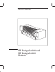
Using this Manual This manual contains information necessary to test, calibrate and service D HP DesignJet 200 plotters (models C3180A and C3181A) D HP DesignJet 220 plotters (models C3187A and C3188A) For information about using these plotters, refer to the corresponding user guides. The procedures described in this manual are to be performed by HPĆqualified service personnel only.
Contents Using this Manual . . . . . . . . . . . . . . . . . . . . . . . . . . . . . . . . . . . . . . . . . . . . . . . . . . ii Safety Symbols . . . . . . . . . . . . . . . . . . . . . . . . . . . . . . . . . . . . . . . . . . . . . . . . . . . . . xi Description . . . . . . . . . . . . . . . . . . . . . . . . . . . . . . . . . . . . . . . . . . . . . . . . . . . . . . . . . . . Applications . . . . . . . . . . . . . . . . . . . . . . . . . . . . . . . . . . . . . . . . . . . . .
Using the Plotter (more User's Guide) . . . . . . . . . . . . . . . . . . . . . . . . . . . . . . . . . . . . . DesignJet 200 Front Panel . . . . . . . . . . . . . . . . . . . . . . . . . . . . . . . . . . . . . . . . . . DesignJet 220 Front Panel . . . . . . . . . . . . . . . . . . . . . . . . . . . . . . . . . . . . . . . . . . Configuring the Plotter (more User's Guide) . . . . . . . . . . . . . . . . . . . . . . . . . . . . . . . . Verifying Plotter Operation . . . . . . . . . . . . . . . . . . . .
Producing an Image . . . . . . . . . . . . . . . . . . . . . . . . . . . . . . . . . . . . . . . . . . . . . . . . . . . . Raster Technology . . . . . . . . . . . . . . . . . . . . . . . . . . . . . . . . . . . . . . . . . . . . . . . . . . Resolution (Dots Per Inch) . . . . . . . . . . . . . . . . . . . . . . . . . . . . . . . . . . . . . . . Dot Size . . . . . . . . . . . . . . . . . . . . . . . . . . . . . . . . . . . . . . . . . . . . . . . . . . . . . . . . Too Much Ink . . . . . . . . . . . . . . . .
Servo Processor System . . . . . . . . . . . . . . . . . . . . . . . . . . . . . . . . . . . . . . . . . . . . . Servo Processor . . . . . . . . . . . . . . . . . . . . . . . . . . . . . . . . . . . . . . . . . . . . . . . . . Processor Support ASIC . . . . . . . . . . . . . . . . . . . . . . . . . . . . . . . . . . . . . . . . . FrontĆPanel Interface . . . . . . . . . . . . . . . . . . . . . . . . . . . . . . . . . . . . . . . . . . . . StepperĆMotor Driver . . . . . . . . . . . . . . . . . . . . . . . . .
Removing the Automatic CartridgeĆAdjust Linkage . . . . . . . . . . . . . . . . . . . . Removing the Stepper Motor . . . . . . . . . . . . . . . . . . . . . . . . . . . . . . . . . . . . . . . . Removing the PinchĆArm Sensor . . . . . . . . . . . . . . . . . . . . . . . . . . . . . . . . . . . . . Removing the Window Sensor . . . . . . . . . . . . . . . . . . . . . . . . . . . . . . . . . . . . . . . Removing the Media Sensor . . . . . . . . . . . . . . . . . . . . . . . . . . . . . . . . . . . . . . . . .
Power On . . . . . . . . . . . . . . . . . . . . . . . . . . . . . . . . . . . . . . . . . . . . . . . . . . . . . . . . . . . . . PowerĆOn Self Test . . . . . . . . . . . . . . . . . . . . . . . . . . . . . . . . . . . . . . . . . . . . . . . . . Extended PowerĆOn Self Test . . . . . . . . . . . . . . . . . . . . . . . . . . . . . . . . . . . . . . . . Mechanical Initialization . . . . . . . . . . . . . . . . . . . . . . . . . . . . . . . . . . . . . . . . . . . .
Plots Joined or Not Plotted . . . . . . . . . . . . . . . . . . . . . . . . . . . . . . . . . . . . . . . . . . . . . HPĆGL Timeout . . . . . . . . . . . . . . . . . . . . . . . . . . . . . . . . . . . . . . . . . . . . . . . . . . . . Incompatibility between Trailing Cable and Main PCA . . . . . . . . . . . . . . . . . Incorrect Line Widths . . . . . . . . . . . . . . . . . . . . . . . . . . . . . . . . . . . . . . . . . . . . . . . . . . Plotter won't Read Setup Sheet; Plots Solid Black Area Fill . . . .
Introduction . . . . . . . . . . . . . . . . . . . . . . . . . . . . . . . . . . . . . . . . . . . . . . . . . . . . . . . . . . SerialĆNumber Format . . . . . . . . . . . . . . . . . . . . . . . . . . . . . . . . . . . . . . . . . . . . . . . . . Identifying a Printed Circuit Assembly . . . . . . . . . . . . . . . . . . . . . . . . . . . . . . . . . . . Part Number . . . . . . . . . . . . . . . . . . . . . . . . . . . . . . . . . . . . . . . . . . . . . . . . . . . . . . .
General Definition of Safety Symbols International caution symbol (refer to manual): the product is marked with this symbol when it is necessary for the user to refer to the instruction manual in order to protect against damage to the instrument. Indicates dangerous voltage (terminals fed from the interior by voltage exceeding 1000 volts must also be marked). Protective conductor terminal. For protection against electrical shock in case of a fault.
Description HP DesignJet 200 and HP DesignJet 220 plotters are largeĆformat, monochrome, inkĆjet plotters that provide hardcopy output of computer program data.
The accuracy of the plotters in drawing a vector is 0.38 mm (0.015 in) or 0.2% of the specified vector length, whichever is greater, at 23 _C (73 _F) at 50Ć60% relative humidity, on HP special polyester film. The resolution of the plotter output is measured in dots per inch (dpi). (Explanation ' chapter 5.
The plotters handle only sheet media, not roll media. Supported standard sizes are as follows: D/A1-size plotters E/A0-size plotters (C3180A and C3187A) (C3181A and C3188A) A, B, C, D, E A4, A3, A2, A1, A0 Metric Oversize A2, A1 A2, A1, A0 Architectural C, D C, D, E, E1 JIS A4, A3, A2, A1 B4, B3, B2 A4, A3, A2, A1, A0 B4, B3, B2, B1, B0 The plotters handle media that does not exceed the following maxima and minima: 210 – 1625 mm 8.
Power Requirements HP C3180A and C3181A DesignJet 200 and HP C3187A and C3188A DesignJet 220 plotters have selfĆadjusting power supplies and do not require a voltage selector or switch settings prior to use. The table below lists the power requirements for the plotters. Power Requirements Source Voltage Requirements: Voltage Max current (rms) 100 V ac 120 V ac 220 V ac 240 V ac 1.4 A 1.
Choosing a Suitable Plotter Environment (Instructions ' User's Guide, chapter 1, w Positioning the plotter.
2Ć4 Site Planning and Requirements C3187Ć90000
Unpacking and Assembling the Plotter When the plotter arrives at the user site: Inspect the shipping container for damage. If the shipping container shows signs of damage, retain it until you have checked the contents of the shipment and verified the performance of the plotter. Unpack and assemble the plotter, following the series of illustrations below. The packaging is due to change in late 1994.
9 10 1 2 11 1 2 12 2 A 2 A B A 1 2 B 1 13 14 2 1 1 1 Inspecting the Plotter for Damage Visually inspect the plotter for damage, scratches, dents, or other mechanical defects. If the plotter is damaged in transit, notify the carrier and the nearest HP Sales and Support Office. Retain the shipping container and insulation material for the carrier's inspection. The Sales and Support Office will arrange for the repair or replacement of the plotter.
Assembling the Legs and Media Bin (Optional) If the user has purchased the optional legs and media bin for the plotter, assemble them following the series of illustrations below: 1 2 3 45 kg (99 lb) 3Ć4 Installation and Configuration C3187Ć90000
4 1 2 6 mm (0.
Installing the Plotter (Instructions User's Guide, chapter 1, Setting up the plotter.) The power cord supplied with the plotter should meet the plug requirements for the geographical area. However, different power cords (international options) are available. (Cable part numbers Service Manual, chapter 10.) Using the Plotter (Instructions User's Guide, chapter 2, Using the plotter.
Configuring the Plotter (Instructions ' User's Guide, chapter 2, w Reconfiguring the plotter.) The User's Guide describes how to D Switch Interface Ports D Configure the following settings using a setup sheet : - Language of demonstration plot and setup sheet Baud rate and parity of serial interface Graphics language HPĆGL timeout period Plot orientation (rotate and mirror) Line merging PenĆpalette settings (width and density) An example of a setup sheet is given on the following page.
The following is a scaled version of a DesignJet 200 setup sheet: 3Ć8 Installation and Configuration C3187Ć90000
Cleaning the Plotter To maintain the plotter in good operating condition, keep it free of dust accumulation, ink, and other contamination. Cleaning intervals are determined by the plotter environment and by the types of plotter supplies used. As with any precision electronics equipment, proper maintenance will help to ensure reliability and prolong product life. WARNING Disconnect the plotter from the power source prior to performing any maintenance.
Loading the Media The media load path begins with the entry platen, which provides a loading surface. (Illustration ' page 10Ć23.) When you assemble the plotter, it is important to correctly position the entry platen to ensure that the dashed lines exactly indicate the permitted rightĆedge loading area. The left side of the entry platen should be pressed up against the left sideĆplate. (Details ' chapter 6.) (Loading Instructions ' User's Guide, chapter 2, w Loading media.
The mediaĆnotĆloaded state can be summarized as follows: Media: not inserted or has not yet reached the primary flag Primary flag: vertical position (idle) Secondary flag: resting on plastic detector housing (idle) Optical sensor: optical path closed by both flags Drive roller: stopped Front panel: Load Media LED on Drive roller stopped Media inserted Primary flag Secondary flag Photo sensor window Media: inserted but has not yet reached the secondary
Drive roller full speed inwards Secondary flag Primary flag Media inserted Photo sensor window Media: reaches the secondary flag Primary flag: rotated 90° counter clockwise (active) Secondary flag: rotated 35° counter clockwise (active) Optical sensor: optical path cleared by both flags Drive roller: full speed inwards, engaging media Front Panel: Load Media LED off, Busy LED on Media Length Measurement: front edge detected When the secondary flag clears
Drive roller slow speed inwards Media inserted Leading edge of media Secondary flag Primary flag Photo sensor window Media: clears the primary flag Primary flag: rotates 90° clockwise (original position Ć active) Secondary flag: still in previous position (active) Optical sensor: optical path blocked by falling edge of primary flag Driver roller: slows down but still rotating inwards...
Drive roller slow speed outwards Media inserted Secondary flag D D D D D D D Leading edge of media Primary flag Photo sensor window Media: pushes the primary flag Primary flag: rotates 90° clockwise (active) Secondary flag: still in previous position (active) Optical sensor: optical path cleared by primary flag Driver roller: rotates slowly outwards...
Advancing the Media The media is advanced by the media drive (XĆdrive) system. Components include: D Media motor (XĆaxis motor) D Worm pinion and helical driveĆroller gear D Drive roller (Illustration ' page 10Ć23.) The main component of the drive system is a fullĆwidth, 6.4Ćcm (2.5Ćinch) diameter roller with an elastomer skin. This roller directly drives the media and provides the surface that references the media to the printĆhead.
Providing a Force on Top of the Media The bail provides a normal force on top of the media. (Illustration page 10Ć25.) When the pinchĆwheels grip the media and the drive roller advances it, the plotter raises the bail. This enables the leading edge of the media to pass below the bail. The plotter then lowers the bail and advances the media to the overdrive roller. The star wheels on the bail are coated with a substance resistant to wet ink, so that they do not leave marks on the media.
Stretching the Media The overdrive roller stretches the media slightly as it is moved through the plotter. It thus reduces bubbling and media cockle caused by media expansion due to the absorption of waterĆbased ink into the media. Even though the geometry chosen for the plotters minimizes the occurrence of this phenomena, it still could occur on very dense plots.
Detecting the Media Edges The plotter detects the left and right media edges using the line sensor located on the carriage. The sensor is composed of D Red LED D Two lenses (caution required when handling) D Collector plate The sensor finds the left media edge when it detects the light from the red LED reflected off the media surface. The black surface of the drive roller absorbs the light. Excessive ink deposits on the driveĆroller can fool the sensor by reflecting the light.
Providing Ink (Carriage Illustration ' page 10Ć21) The plotters use two HP DeskJetĆtype cartridges, each containing 50 nozzles. The cartridges are staggered such that two nozzles on each one are not used. The main components of a cartridge are the D Plastic housing D SpringĆbag ink reservoir D Flex circuit The spring bag provides a negative pressure inside the ink supply to prevent ink from flowing out through the nozzles.
The geometry of the nozzle is important to maintain drop shape and direction. The distance of the head from the writing surface can determine image sharpness. As the distance increases, the drop shape and directionality degrade and are more difficult to predict. The two black print cartridges snap into the cartridge chutes (carriage snaps).
Producing an Image The plotters are raster based. They plot using dots to represent the data. Thus a line is made up of a series of dots. Vector B 95 C D Raster 45 14 A The resolution of a raster plotter is the number of dots per inch (dpi) it can place along one of two orthogonal axes. refers to the ability of the plotter to print a single dot at every location on a grid.
Each dot produced by a 300Ćdpi cartridge has a diameter of 0.0055 in. The dot size must be larger than 1/300th of an inch (0.0033 in.) so that when a singleĆdotĆwide line is printed, dots overlap and the line appears to be continuous. A 600Ćdpi grid contains four times as many dots as a 300Ćdpi grid. This means that four times as much ink can be laid down on a 600Ćdpi grid. Media cannot absorb that much ink effectively; it puddles, runs, and dries slowly.
Media Type Print Quality Resolution (DPI) # of Passes Carriage Speed Swath Delay Pass Density Draft 300x300 1 24ips 0 50% Final 300x300 1 16.7ips 1sec 100% Vellum/ Transl Draft 300x300 1 24ips 0 50% Vellum/ Transl/Film Final 300x300 2 16.7ips 1sec 50% Print Quality Resolution (DPI) # of Passes Carriage Speed Swath Delay Pass Density Draft 300x300 1 24ips 0 50% Final 300x300 1 16.
Aligning the Cartridges The cartridgeĆalignment system is composed of D D D D D Stepper motor Adjustment linkage Adjustment cam Adjustable cartridge chute Carriage drive (Illustrations ' pages 10Ć15 and 10Ć21.) The following operation is used to align one cartridge with respect to the other in the XĆaxis (media axis). (YĆaxis and ZĆaxis realignments are done by varying the firing timing of each nozzle resistor.
Servicing the Cartridges (Illustration ' page 10Ć17.) Various important cartridgeĆmaintenance operations are performed at the service station: D Cartridge wiping D Cartridge capping D Nozzle spitting During operation of the cartridge, ink accumulates on the nozzle plate along with paper dust and other substances foreign to the cartridge. If not removed, this buildup can affect nozzle directionality and lead to nozzle failure.
Ink evaporates if you expose nonĆfiring nozzle plates to the open environment. Vapor loss changes the physical properties of the ink remaining in the area of the nozzle plate. The ink may form viscous plugs that fully or partially clog nozzles. To reduce the loss of ink vapor and thus prevent the nozzles from drying out when the cartridges sit idle, the service station automatically places a cap over the nozzle plates.
System Data Flow I/O Buffer Data characters One at a time Data characters 500 Bytes Firmware Graphics Module Parser Physical Graphic objects Swath Area Display List I/O Interrupt Swath Graphic objects Physical Input/Output Firmware Print-Engine Control Module VRC, RRC Rasterized object Swath Data Swath Holding Area Swath Manager The user's computer is connected to the plotter through a physical input/output (I/O) connection.
The vectorĆtoĆraster converter (VRC) or rasterĆtoĆraster converter (RRC), depending on the data format sent, rasterizes the data from the display list, swath by swath, and sends the swaths to a swath holding area. The swath holding area is part of the DRAM that is specially allocated for this purpose. The swath holding area is large enough to hold up to three swaths at a time.
Plotter Architecture The plotters have the multiprocessor architecture shown in the following diagram: Main Processor (80960KA) Internal Memory (ROM/RAM) Expansion Memory (SIMM DRAM) I/O (Centronics) (RS–232) 80960 bus Encoders Shuffler ASIC Swath RAM (256 KB) Support ASIC Motor Drivers Nozzle Timing ASIC Carriage Processor (8051) Servo Processor (8052) EEPROM (256) Cartridge Drivers Sensors Line Detector Front Panel Plotter Architecture The plotter electronics, besides sensors and cables,
Main PCA (Part illustration ' page 10Ć9.
The main processor system consists of the following: Main processor (80960) ROM Processor support ASIC Shuffler ASIC with swath memory Input/output interfaces DRAM To Servo Processor System 80960 CPU Demultiplexed Bus Interface Processor Support ASIC RS-232 Interface Swath RAM Shuffler ASIC To Carriage Processor System DRAM SIMM Socket Centronics Interface 4x8-Mbit ROM 2-MB DRAM Main-Processor-System The main processor interprets graphicsĆlanguage com
The processor support ASIC provides support for the main processor, and an interface between the main processor and the servo processor. The shuffler ASIC and the swath memory shuffle the rowĆoriented image data in the system memory into columnĆoriented nozzle data needed by the print cartridges.
The main processor controls the DTR (Data Terminal Ready) signal using a bit in the parallel I/O control register. Whenever the power to the plotter is on, RTS (Request To Send) is set active. No other modem signals are controlled or monitored. The reset state of the DTR signal is undefined. During initialization, the main processor first sets the DTR control bit to 1, which signals the host that the interface cannot accept data.
The servo processor system consists of the following: Servo processor (8052) Processor support ASIC FrontĆpanel interface StepperĆmotor driver CarriageĆprocessor interface Various sensor inputs EEROM Motor Position Encoders To Main Processor System Front-Panel Interface Sensors 8052 Servo Processor Processor Support ASIC Stepper-Motor Driver Motor Drivers EEROM To Carriage Processor System Servo Processor System The servo processor controls all of the plo
The front panel consists of nine LEDs and eight switches. The servo processor interface to the front panel consists of nine control signals and two sense signals. The servo processor controls a stepper motor used for printĆcartridge servicing and alignment. The servoĆprocessor serial port is used to communicate with the carriage processor.
The following are the power components on the main PCA: Two motor driver ICs and heatsinks. To regulate the amount of energy given to the printĆcartridge heating resistors, a precise voltage regulator controls the printĆcartridge voltage supply. The regulator power device is located on the main PCA, but the cartridge resistors and drivers are located on the carriage PCA.
Carriage PCA The carriage PCA has four main functions: The nozzleĆtiming ASIC controls the firing of the print cartridges, using data from the shuffler ASIC on the main PCA. A linear encoder senses the carriage position. A line sensor enables automatic printĆcartridge calibration. A thermistor monitors the temperature near the print cartridges. The carriage PCA is installed in the carriage assembly, componentĆside down to accommodate the operation of the linear encoder.
The carriage processor dedicates its address/data bus to interface with the nozzleĆtiming ASIC. The ASIC is also connected to the shuffler ASIC by a synchronous serial channel. The nozzleĆtiming ASIC applies the shuffled data it receives from the shuffler ASIC to the cartridge drivers, controlling the firing time and sequence of the printĆcartridge nozzles. The outputs controlling the print cartridge drivers are disabled while the reset signal is active.
Front Panel PCA The plotters use the same frontĆpanel PCA as the DeskJet 550. The frontĆpanel consists of nine LEDs and eight switches, mounted on the PCA, which is deeply recessed behind a plastic housing containing the key pad. The keys act on the switches through push rods. Light pipes transmit the light from the LEDs to the display area. The LEDs are driven by drivers on the main board, under the control of the servo processor.
Power Supply An autoĆranging power supply is located in the electronics enclosure. It accepts and automatically adjusts to an ac input of 90 V through 264 V and produces regulated voltages of +5 V, +12 V and -12 V, and an unregulated +24 V. These voltages are used as follows: Voltage Use +24 V Motor drivers and voltage regulator on the main PCA. (Regulated +20 V for cartridge circuits on the carriage PCA). +12 V Fan power and RS-232 driver. –12 V RS-232 driver. +5 V IC power and sensors.
Safety Precautions (Safety symbols Immediately after the table of contents.) Review WARNING and CAUTION symbols and instructions before you service the plotters. Follow these warnings and cautions for your protection and to avoid damaging the plotter.
Required Tools The following are the tools required to disassemble and repair the plotters.
D Nut driver with indicated attachments: and 3/16 inch 5.
Repair Procedures Ensure that the plotter is switched and that the power cord and interface cable(s) are not connected to it. At the back of the plotter, ensure that the two small wire clamps of the parallel port are positioned vertically. Power inlet: cord not connected Remove the screws that attach the electronicsĆenclosure cover to the electronics enclosure.
Push the cover up so that its tabs can slide out of the slots at the top of the electronics enclosure. Carefully pull the cover clear of the plotter.
The user may have installed an optional DRAM SIMM in the plotter. Perform the following procedure, if you need to remove it: Read page 6Ć2. Remove the electronicsĆenclosure cover page 6Ć5. Locate the DRAMĆSIMM slot at the bottom of the main PCA. Slot for DRAM SIMM While pushing the two metal springs apart at the ends of the slot, tilt the outer edge of the DRAM SIMM downwards.
To reinstall the SIMM, perform the following procedure: Hold the memory module by its edges with the nonĆmetallic edge toward you and the notch to your left. Tilt the nonĆmetallic edge downwards and firmly push the module into the slot. Gradually tilt the module upwards and push it in until it clicks into place.
Remove the electronicsĆenclosure cover page 6Ć5. Remove the two screws from the serial (RSĆ232ĆC) connector. 3/16 inch Remove the two screws from the parallel connector. D/A1Ćsize plotters only: Open the flexible, DANGER HIGH VOLTAGE," insulation cover.
Disconnect all 12 cable connectors from the main PCA. CAUTION Do not force the frontĆpanel PCA cable out of its clamp. First pull the clamp gently towards you to release the cable; then pull the cable easily out of the clamp.
If you are installing a new PCA, perform the following extra steps: Remove the original EPROMs or masked ROMs from their sockets, and install them on the new PCA. EPROMs U28 U29 U9 U4 Empty pair of holes Masked ROMs The original PCA contains four EPROMs two masked ROMs. The EPROMs each have one pair of pins less than the masked ROMs; if you are installing EPROMs, leave the rightmost pair of holes empty in each socket. U28 U9 U29 Empty Empty U4 (Part numbers chapter 10.
Remove the electronicsĆenclosure cover page 6Ć5. Open the flexible, DANGER HIGH VOLTAGE," insulation cover. Disconnect the ac connector and the dc powerĆdistribution connector from the powerĆsupply PCA.
Remove the six screws that secure the powerĆsupply PCA to the electronics enclosure. Lift the powerĆsupply PCA clear of the plotter.
Disconnect the fan connector from the main PCA and holding clip. Remove the electronicsĆenclosure cover page 6Ć5. Open the flexible, DANGER HIGH VOLTAGE," insulation cover. Fan connector Remove the two screws that secure the fan to the electronics enclosure. Lift the fan clear of the plotter.
Open the window. the top screw of the right front trim (two full turns). Torx-15 Carefully push the right endcover and the window apart, far enough to lift the window up so that the right pivot just clears its socket. C3187Ć90000 Move the window to the right so that the left pivot slides out of its socket, and lift the window clear of the plotter.
Remove the window page 6Ć15. Loosen the two latch screws on the underside of the center cover. Torx-15 Slide the two latches horizontally towards the center of the plotter, clear of the two endcovers.
Remove the screws from the back of the center cover. Torx-15 Slide the center cover vertically upwards, and lift it clear of the plotter.
Remove the window page 6Ć15, and the center cover page 6Ć16. Remove the two screws on the left front trim and the two screws on the left back trim. Torx-15 CAUTION When replacing screws on any plastic part, always begin by gently twisting the screw in anticlockwise with your hand, until the screw finds the thread path and clicks, and then twisting the screw in clockwise with your hand, before using a screwdriver. This is to avoid crossĆthreading.
Remove the window page 6Ć15, and the center cover page 6Ć16. Remove the two screws on the right front trim and the two screws on the right back trim. Torx-15 CAUTION When replacing screws on any plastic part, always begin by gently twisting the screw in anticlockwise with your hand, until the screw finds the thread path and clicks, and then twisting the screw in clockwise with your hand, before using a screwdriver. This is to avoid crossĆthreading.
Remove the window page 6Ć15. Remove the center cover page 6Ć16. Remove the left endcover page 6Ć18. Remove the two shoulder screws that attach the automatic cartridgeĆadjust linkage to the left sideplate and lift the linkage clear of the plotter. Torx-15 Detach the linkage spring from the YĆtensioner bracket.
Remove the electronicsĆenclosure cover ' page 6Ć5. Remove the window ' Open the flexible, DANGER HIGH VOLTAGE," insulation cover. page 6Ć15. Remove the center cover ' page 6Ć16. Remove the left endcover ' page 6Ć18. Disconnect the stepperĆmotor cable connector from the main PCA and the holding clip.
Loosen the right screw and remove the left screw that attaches the stepper motor to the left sideplate. Move the stepper motor toward the rear of the plotter. Torx-10 Loosen Remove CAUTION Do not crossĆthread or overĆtighten the screws. 6Ć22 Removal and Replacement Pull the stepperĆmotor cable gently out from the electronics enclosure, through the hole in the left side of the electronics enclosure, and lift it and the stepper motor clear of the plotter.
Remove the electronicsĆenclosure cover ' page 6Ć5. Remove the window ' page 6Ć15. Remove the center cover ' page 6Ć16. Disconnect the pinchĆarmĆsensor cable connector from the main PCA and from the ferrite on the right sideplate. Remove the right endcover ' page 6Ć19.
Remove the electronicsĆenclosure cover page 6Ć5. Disconnect the windowĆsensor cable connector from the main PCA. Remove the window page 6Ć15. Remove the center cover page 6Ć16. Remove the right endcover page 6Ć19. Window-sensor connector Carefully feed the windowĆsensor cable out from the electronics enclosure and from under the motor assemblies, unclipping it from the holding clips and ferrite.
Slide the cable and connector up through the fastener near the right front trim. Remove the screw that attaches the window sensor to the right front trim. Torx-8 Sensor Fastener CAUTION Do not crossĆthread or overĆtighten the screw. Torque = 3 lb in. ( ≅ 0.35 Nm) Lift the sensor, with cable, clear of the plotter.
! Remove the electronicsĆenclosure cover page 6Ć5. Remove the window page 6Ć15. Remove the center cover page 6Ć16. Disconnect the mediaĆsensor cable connector from the main PCA, and from the holding clip and ferrite on the right sideplate. The ferrite holder opens from the top Remove the right endcover page 6Ć19.
Remove the screws that attach the bottom cover to the plotter, and lift the cover clear of the plotter. Pull the media sensor straight out towards you, freeing it from the underside of the entry platen. D/A1Ćsize plotters have 8 screws. E/A0Ćsize plotters have 10 screws. Torx-20 Cut the plastic tie that fastens the mediaĆsensor cable to the underside of the entry platen.
Insert the tĆshaped flag in the indicated position. Let the tĆshaped flag rotate to its correct position. Insert the bellĆshaped flag in the indicated position. Let the bellĆshaped flag rotate to its correct position.
If you are installing a new trailing cable, make sure the main PCA is compatible with it. (Details chapter 9.) Disconnect the trailingĆcable connector from the main PCA. Remove the electronicsĆenclosure cover page 6Ć5. Remove the window page 6Ć15. Remove the center cover page 6Ć16. D/A1Ćsize plotters only: Open the flexible, DANGER HIGH VOLTAGE, insulation cover. Trailing-cable connector Flex the cover to open it. Do not detach the cover from the plotter.
Disconnect the trailingĆcable connector from the cartridgeĆcarriage PCA. Cartridge-carriage PCA Trailing-cable connector If you need to change the trailing cable: Cut the two plastic ties that hold the cable to the rear tray and bracket. Free the cable from the rear tray and bracket, pulling it up through the slot at the top of the electronics enclosure assembly.
If you don't need to change the trailing cable, but do need to remove it to access other parts: Carefully remove the rightĆhand cartridge spring from the cartridge carriage. Remove the two screws that attach the trailingĆcable rear tray to the top of the electronics enclosure. Torx-20 Rear tray Remove the trailingĆcableĆbracket screw from the cartridge carriage.
Remove the electronicsĆenclosure cover ' page 6Ć5. Remove the window ' page 6Ć15. Remove the center cover ' page 6Ć16. Remove the right endcover ' page 6Ć19. Unclip the windowĆsensor cable and frontĆpanel cable from their holding clip on the underside of the frontĆpanel assembly. Front-panel cable Window-sensor cable Take note of the correct positioning of the frontĆpanel cable for reassembling.
Carefully feed the frontĆpanel cable out from the electronics enclosure, through the flat ferrite on the right sideplate, and out from under the motor assemblies. Remove the two screws and washers that attach the frontĆpanel assembly to the right sideĆplate, and lift the frontĆpanel assembly, with cable, clear of the plotter.
Remove the electronicsĆenclosure cover page 6Ć5. Remove the window page 6Ć15. Remove the center cover page 6Ć16. Remove the right endcover page 6Ć19. Remove the frontĆpanel assembly page 6Ć32. On the underside of the frontĆpanel assembly, press the four transparent plastic tabs inwards and remove the PCA and LED assembly.
Disconnect the carriageĆmotor cable from the main PCA (connector labelled Y), and from the lowest ferrite holder on the rightĆhand side of the plotter. Remove the electronicsĆenclosure cover page 6Ć5. Remove the window page 6Ć15. Remove the center cover page 6Ć16. Remove the right endcover page 6Ć19.
Rotate the motor in the indicated direction. Pull the motor down, clear of its bracket.
& $ * ( # $ " Remove the electronicsĆenclosure cover page 6Ć5. Remove the window page 6Ć15. Disconnect the mediaĆmotor cable from the main PCA (connector labeled X) and from the uppermost ferrite holder on the rightĆhand side of the plotter. Remove the center cover page 6Ć16. Remove the right endcover page 6Ć19. Remove the frontĆpanel assembly page 6Ć32. Remove the carriage motor page 6Ć35.
Remove the two screws that secure the media motor to the mediaĆmotor mount. Pull the media motor towards the rear of the plotter. Disconnect the flat encoder cable from the motor, and lift the motor clear of the plotter. Reassembling: The worm pinion and driveĆroller gear mesh slightly during use. Don't install a new motor and an old gear, or vice versa: install the gear that comes with the motor. Apply the grease that comes with the new motor to the worm pinion and driveĆroller gear.
WĂAĂRĂNĂIĂNĂG Remove the window page 6Ć15. Remove the center cover page 6Ć16. " ! " Remove the right endcover page 6Ć19 Remove the left endcover page 6Ć18. CAUTION The encoder strip is fragile. Do not damage it. Lay it on a flat surface when it is not in the plotter.
Compressing the encoder springĆbracket to release tension on the encoder strip, carefully release the encoder strip from the service station. Encoder strip Spring bracket 1 2 Compress Release Service station Carefully pull the encoder strip through and out of the carriage assembly. Lay the encoder strip on a flat surface.
Ensure that the encoder strip is oriented with the transparent area up, and with three holes on the left side and one hole on the right side. Thread the strip through the apertures in the cartridgeĆcarriage assembly. With washer and nut, secure the encoder strip to the service station. Press the forward end of the encoder springĆbracket slightly inward and place the encoder strip between the tabs and over the threaded post on the encoder springĆbracket.
With washer and nut, secure the encoder strip to the encoder springĆbracket. 5.5 mm Slide the carriage back and forth the length of its travel to ensure free movement.
Remove the screw that attaches the trailingĆcable guide to the tensioner housing. CAUTION Handle the trailing cable and the trailingĆcable guide with care. Torx-15 Remove the window page 6Ć15. Trailing-cable guide Remove the center cover page 6Ć16. Remove the left endcover page 6Ć18. Remove the right endcover page 6Ć19.
Remove the screw inside the ferrite ring. Slightly lift up the guide and carefully remove the ferrite ring. Torx-15 Move the trailingĆcable guide towards the rear of the plotter, rotate it to clear the arm of the cartridgeĆadjustment cam on the cartridge carriage, and lift the trailingĆcable guide clear of the plotter. CAUTION Be careful not to scrape the cartridgeĆcarriage PCA with the trailingĆcable guide if you are sliding the guide under the trailing cable.
Remove the window page 6Ć15. Remove the center cover page 6Ć16. Remove the screw that attaches the trailingĆcable guide to the tensioner housing. Remove the left endcover page 6Ć18. Slide the cartridge carriage towards the center of the plotter in order to access the tensioner. Torx-15 Trailing-cable guide Tensioner housing Remove the tensionerĆplate screw. Torx-15 CAUTION C3187Ć90000 The tensioner plate is under spring tension.
Carefully move the tensioner plate to the right until it clears the slot in the housing. Carefully move the right end of the tensioner plate up and clear of the retaining tab. Tab Slot Tensioner plate Decompress the tensioner spring by allowing the tensioner plate to move toward the rear of the plotter. Tensioner spring 6Ć46 Tensioner plate Remove the YĆtensioner spring and YĆtensioner from the housing.
the YĆtensioner housing screw. Slide the YĆtensioner housing out from the YĆtensioner bracket. Torx-15 Loosen Release the main idler from the cartridgeĆcarriage belt. C3187Ć90000 Y-tensioner bracket Y-tensioner housing Lift the YĆtensioner housing clear of the plotter.
CAUTION If you are installing a new cartridge carriage or a new carriage PCA, ensure that the plotter firmware is compatible with it. Incompatibilities could destroy the cartridges. (Details chapter 9.) Remove the two screws that secure the encoderĆstrip bracket to the serviceĆ station housing. Torx-15 Encoder-strip bracket Remove the window page 6Ć15. Remove the center cover page 6Ć16. Remove the left endcover page 6Ć18.
Holding the serviceĆstation sled about 1 cm (or about 1/2 inch) to the left of its normal position with one hand, tilt the forward edge of the serviceĆstation cover up and lift the cover clear of the serviceĆstation housing. Sled 1 2 Cover Lift the serviceĆstation sled up slightly and release the sled spring from the serviceĆstation housing.
Lift the serviceĆstation sled clear of the serviceĆstation housing and the plotter. Remove the screw and washer that attach the encoderĆstrip spring to the spring bracket. Move to the right side of the plotter. Pressing the small drive belt against the tensioner wheel to loosen the belt, slide the belt off of the motor gear; then carefully release your hand from the the tensioner wheel.
Remove the encoderĆstrip spring. Remove the double pulley from the YĆdrive bracket. While doing this keep the palm of one hand beneath the double pulley to catch the doubleĆpulley bushing. Washer Bracket Double pulley Bushing Disconnect the trailingĆcable connector from the cartridgeĆcarriage PCA.
Remove the right spring from the cartridgeĆcarriage assembly. Remove the screw that attaches the trailingĆcable bracket to the carriage assembly. Torx-10 Lift the trailingĆcable and bracket clear of the carriage assembly. Slide the cartridge carriage to the left side of the plotter.
CAUTION In the following step, take care when moving the cartridgeĆcarriage over the plastic projection at the top left end of the serviceĆstation housing. Too much force may damage the housing or the carriage. Grasp the carriage rear preload bushing (rides on the rear slider rod), and move the carriage to the left and free of the slider rods.
Set the carriage assembly upsideĆdown on a flat surface. Using a small, standard screwdriver, remove the left and right belt clamps from the carriage assembly. Belt clamp CAUTION Be careful not to damage the clamps. Reassembling: Correctly install the clamps, so that they don't fall out during plotter operation! Remove the main drive belt from the carriage assembly. Main drive belt Calibration: After having reassembled the plotter, perform the cartridgeĆalignment routine chapter 7.
Remove the electronicsĆenclosure cover page 6Ć5. Remove the window page 6Ć15. Note the position of the bailĆsensor cable for reassembly. Incorrect positioning could cause obstruction of the cartridge carriage and motor gears. Remove the center cover page 6Ć16. Remove the right endcover page 6Ć19. Bail sensor Disconnect the bailĆsensor cable connector from the main PCA, and from its ferrite and holding clip on the right sideplate.
Open the window. Move the cartridgeĆcarriage to the extreme left. Cartridge carriage Push both of the plastic ends of the bail towards each other to release them from the holes in the sideplates, and lift the bail up and clear of the plotter.
Remove the nut and washer that attach the encoder strip to the encoderĆstrip bracket. Remove the window page 6Ć15. Remove the center cover page 6Ć16. 5.5 mm Remove the left endcover page 6Ć18. Move the cartridge carriage to the center of its travel.
Remove the three screws that secure the serviceĆstation cover to the serviceĆstation housing. Torx-15 Holding the serviceĆstation sled about 1 cm (or about 1/2 inch) to the left of its normal position with one hand, tilt the forward edge of the serviceĆstation cover up and lift the cover clear of the serviceĆstation housing.
Lift the serviceĆstation sled clear of the serviceĆstation housing and the plotter. Remove any wet ink from the wiper in the serviceĆstation housing. Remove the wiper from the top of the wiper rod by pulling the wiper up. Wiper Remove the screw and washer that secure the wiper rod and rocker to the left sideplate, and lift the rod and rocker clear of the plotter. Remove the three screws that attach the serviceĆstation housing to the left sideplate.
Overdrive roller Remove the clutch retaining ring that secures the overdrive clutch to the overdrive roller. You can do this with a needleĆnose pliers, having to remove the service station. (The service station is not shown in the diagram.) Remove the window page 6Ć15. Remove the center cover page 6Ć16. Remove the left endcover page 6Ć18. Lift the left front trim clear of the plotter. Remove the bail page 6Ć56.
Move the overdrive roller to the right until it has completely cleared the left sideplate but not entered the hole in the right sideplate. Release the overdrive roller from the overdrive bushing (small black clips underneath the media separator), and lift the overdrive roller clear of the plotter.
Remove the three indicated screws from the left sideplate. Remove the window page 6Ć15. Remove the center cover page 6Ć16. Remove the left endcover page 6Ć18. Remove the right endcover page 6Ć19. Remove the overdrive roller page 6Ć60. 1 2 3 Torx-15 Torx-20 LEFTĆHAND SIDE Remove the two indicated screws from the right sideplate. Lift the overdrive enclosure clear of the plotter.
Position the overdrive enclosure between the two sideplates. CAUTION Take care not to damage the mediaĆsensor flags. The overdrive enclosure should not touch them. Replace the two indicated screws. ( dogĆpoint screws.
Insert the two indicated screws, but DO NOT tighten them. ( dogĆpoint screws.) Torx-15 LEAVE LOOSE 3 4 LEFTĆHAND SIDE Replace the indicated screw and tighten it, thus aligning the overdrive enclosure with the left sideplate. Torx-20 RIGHTĆHAND SIDE Tighten the two screws you inserted in step 3.
Remove the window page 6Ć15. Remove the center cover page 6Ć16. Remove the three indicated screws from the left sideplate. Remove the left endcover page 6Ć18. Remove the right endcover page 6Ć19. Remove the overdrive roller page 6Ć60. Unscrew the pinchĆarm lever and right front trim and lift them clear of the entry platen, taking care not to damage the window sensor. 1 Torx-20 2 Remove the overdrive enclosure page 6Ć62.
Pull the entry platen out from the plotter in order to access the media sensor. Detach the mediaĆsensor holder from the underside of the entry platen by pulling the holder straight out. Cut the plastic tie that fastens the mediaĆsensor cable to the underside of the entry platen. Lift the entry platen clear of the plotter. CAUTION Take care not to cut the mediaĆsensor cable itself.
The order in which you replace the screws on the entry platen is important. If the plotter is attached to a support, detach it. Turn the plotter on its back. Reconnect the media sensor to the entry platen (see also page 6Ć26). Position the entry platen between the two sideplates. Position the top of the entry platen under all of the small pivots on the inside of both sideplates, except the back pivot. Rest the entry platen against the back pivot.
Replace the two indicated screws. ( dogĆpoint screws.) Torx-15 3 4 Replace the indicated screw. Replace the screws on the bottom cover. Torx-20 D/A1Ćsize plotters have four screws. E/A0Ćsize plotters have five screws. 5 Turn the plotter to its correct position. Before reĆinstalling the overdrive enclosure, ensure that both flags on the media sensor move freely when you pass a sheet of media over them.
Remove the electronicsĆenclosure cover page 6Ć5. Remove the window page 6Ć15. Remove the center cover page 6Ć16. In the following step, take care not to damage the bail sensor. CAUTION Remove the three screws that attach the mediaĆmotor mount to the right sideplate. Press down on the media mount as you replace the three screws. This is to ensure correct spacing between the drive roller and the cartridge nozzles. (Details chapter 9.
Remove the drive roller from the plotter. Reassembling: Ensure that the bearing assembly at the right end of the drive roller is seated in the right sideplate and completely on the right side of the axial bias plate. Calibration: Perform the accuracy calibration after installing the drive roller. (Details chapter 7.
The camĆgear support is a new part, introduced with the DesignJet 220 to help solve failures in the bailĆlift mechanism. It replaces the TeflonĆwasher solution of the DesignJet 200. A service note describes how to remove the Teflon washers and install the camĆgear support and associated parts on a DesignJet 200. (Details chapter 9.
Remove the drive roller page 6Ć69. Push the pinchĆarm lever (located on the right side of the entry platen) into the vertical position. Remove the screws on the entry platen, page 6Ć65, and pull it slightly forward. On the right side of the plotter, disconnect the rockerĆplate tension spring to relieve any remaining tension on the pinchĆarm lift mechanism.
On the right side, loosen the camĆjournal screw 12 turns counterĆclockwise and push the screw in towards the center of the plotter. Torx-8 Repeat the previous step and try to pull the cam journal and rear wire link to the right and clear of the bar cam.
Grasp the cam journal on the left side of the plotter with your left hand. Reach around to the front of the plotter and push the top of the bar cam slightly towards the rear of the plotter, simultaneously pulling the cam journal to the left, so that the bar cam can begin to slide out of the left sideplate.
When to Calibrate the Plotter Indications or Repairs Performed Calibration Required Jagged lines on plots Cartridge Alignment Cartridges are reseated or replaced Cartridge Alignment Drive roller is removed or replaced Accuracy Calibration Media (X-axis) motor is replaced Accuracy Calibration Configuration-plot X-mark distance is not 500mm ( 1mm) Accuracy Calibration Carriage or carriage LED is removed or replaced Cartridge Alignment and Setup-Sheet Calibration Edge-detect failures occur Cartr
FrontĆPanel Keys in Service Mode Pressing any single frontĆpanel key in service mode performs the same operation as in normal mode. However, in service mode, you can also use combinations of keys, to perform the various service tests and calibrations. With this intent, the Replot key acts as a SHIFT key, and the Cancel key acts as an ALT key. The following illustration indicates which service tests and calibrations are assigned to which frontĆpanel keys.
Cartridge Alignment When to Align Cartridges If you suspect that the plotter is not producing plots of the highest quality, you can run a simple cartridgeĆalignment routine that will ensure that the print cartridges are aligned. Perform this routine also after clearing a media jam. The alignment is also automatically performed after each time you replace or reseat the print cartridges. In this case, the plotter uses the first sheet of media that you load to perform the alignment.
Gap } } Left cartridge Right cartridge If any of the leftĆcartridge or rightĆcartridge lines includes gaps, then the corresponding print cartridge should be either cleaned or replaced as appropriate.
Accuracy Calibration Purpose The accuracy calibration procedure is used to correct the endĆpoint accuracy of the media axis. The cartridge axis does not require calibration and is used to calibrate the media axis.
Performing the Accuracy Calibration , Enter service mode page 7Ć2. . Plot a service configuration plot page 8Ć23. A Measure the distance between the centers of the X" marks on the configuration plot. An accuracy calibration is needed if this distance is not 500 mm (20 in) 1 mm (0.04 in) under normal environmental conditions. If the measured accuracy, media thickness, or environmental conditions vary greatly from the factory standards, recalibrate the plotter by continuing with the following steps.
When the Ready LED lights up, hold down the SHIFT key and press Accuracy Calib. Read, SHIFT The Busy LED lights up. The plotter takes about 3 minutes to read the calibration sheet, to calculate the calibration data, and to save the data in the EEROM. During this time, the plotter appears almost motionless for short intervals. The plotter then ejects the sheet. Accuracy Calib. Read Unload the sheet. Bail Calibration In this procedure, the `up' position of the bail assembly is calibrated.
MediaĆSensor Calibration The mediaĆsensor calibration measures the position of the mediaĆsensor levers with respect to the drive roller. A value is stored in the EEROM when the procedure is completed. Perform the mediaĆsensor calibration whenever: D D D D The EEROM is cleared The main PCA is replaced The media sensor is removed or replaced The leading and trailing margins of a plot are greater than 17 mm (0.67 in).
SetupĆSheet Calibration This calibration calibrates the power of the LED situated on the cartridge carriage, for better scanning of the setup sheet. Perform the setupĆsheet calibration whenever: D D D D The EEROM is cleared The cartridge carriage is replaced The optical sensor on the cartridge carriage is replaced Problems frequently occur with setupĆsheet scanning To calibrate the LED, perform the following procedure: Enter service mode D page 7Ć2. Load a blank sheet of paper.
8 Troubleshooting 8Ć0
Power On The plotters automatically perform a series of internal self tests and mechanical initialization sequences whenever the user switches the plotter on. These are completed after about 30 seconds. If a failure occurs, an error is indicated on the frontĆpanel LEDs. You can perform a failure analysis by interpreting the LED error code. (Details later in this chapter.) PowerĆOn Self Test The powerĆon self test does the following: 1 Initializes the servo processor. 2 Initializes the main processor .
Extended PowerĆOn Self Test Perform the extended powerĆon test whenever the plotter passes the normal powerĆon test, but does not function properly. To begin the extended powerĆon test, perform the following procedure: , Switch the plotter off. Access Cartridges . While holding the Access Cartridges key down, switch the plotter on. A Once the Busy LED lights up, release the Access Cartridges key.
What You Should See and Hear When you turn on the plotter, the following happens: 1 All six LEDs light up for a brief moment; then the Busy LED remains on. Busy 2 The stepper motor makes a buzzing noise. 3 The cartridge carriage knocks against the leftĆhand side. 4 The carriage moves across the plotter and knocks three times against the rightĆhand side. 5 The carriage returns to the leftĆhand side.
Errors Indicated by LEDs Error The Error LED on the front panel works in combination with the other LEDs to specify the type of error that has occurred. The three possible states of any LED are represented like this: Off On Flashing User errors are associated with user settings or user actions and may be solved by the user without calling a Customer Engineer. They are indicated by the Error LED flashing. (Further Information D User's Guide, chapter 4, .
Error and Busy flashing Error Busy Possible Causes Corrective Action The serialĆinterface settings are different on the plotter and on the software. 1. Print a setup sheet and check the plotter's current settings for Baud Rate and Parity. 2. Compare these with the current settings of the same two items for your application software. They must be the same. 3. If necessary, change the plotter's settings. The serialĆinterface cable is not correctly connected. Connect the cable correctly.
System errors are associated with plotter hardware failure that needs to be repaired by a Service or Customer Engineer. System errors are indicated by the LED lit and steady. represents the frontĆpanel In the tables on the following pages, the symbol LEDs, where, in this case, the Error, Paper and Ready LEDs are lit and steady, and the other LEDs are off.
Error and Ready LEDs lit and steady: Memory errors. LEDs lit and steady 8Ć8 Error Number and Description Corrective Options 81. Failure of ROM test Replace EPROMs. If problem remains, replace main PCA. 21. Failure of DRAM quick test Replace main PCA. 85. Failure of DRAM full test Replace main PCA 49. Failure of Swath RAM test Replace main PCA 113. Failure of EEROM test Replace main PCA. 53. DRAM SIMM failure Replace DRAM SIMM. If problem remains, replace main PCA. 117.
Error and Load Media LEDs lit and steady: MediaĆpath/servo errors. LEDs lit and steady Error Number and Description Corrective Options 82. Shutdown of media axis (XĆaxis) See D later in this chapter, w . 22. Shutdown of carriage axis (YĆaxis) See D later in this chapter, w . 86. CarriageĆaxis failure Check encoder strip, carriage assembly, trailing cable, main PCA. 50.
Error and Cartridge LEDs lit and steady: Miscellaneous errors. LEDs lit and steady 8Ć10 Error Number and Description Corrective Options 88. Processor fault At the time of printing of this manual, this error should not occur. If it does occur, consult recent service notes for a possible solution. If no service note deals with this error, report the problem to the HP Response Center. 28.Communication failure between the main and servo processors. Communication occurs through the processorĆsupport ASIC.
FirmwareĆCode Revision Level To check the firmwareĆcode revision level that the plotter is using, print a setup sheet or a service configuration plot. Troubleshooting Tips Repair + Calibrate After you have made a repair, consider if any calibrations have been affected. Print Quality You can use the user demonstration plot to look at overall print quality including smoothness and straightness of lines, arcs, circles, and characters.
Servo ControlĆSystem Failures MediaĆAxis (XĆAxis) Shutdown In the case of a mediaĆaxis shutdown, try one or more of the following corrective actions: D Clear any binding in the mediaĆaxis mechanics due to a media jam. (Do not pull the media along the carriage axis. Doing so could break the mediaĆsensor flags.) D Remove the two screws that attach the driveĆroller gear to the drive roller. This should enable you to manually spin the drive roller. If it does not, the roller is probably jammed.
Misaligned Cartridge Caps If a customer is complaining about shortened cartridge life or frequent cartridge failure, you should check the cartridgeĆcap alignment (procedure below). This is especially true if the problem is always happening to the same cartridge. A sure sign of a misaligned cap is excess ink around the cap and inside the ink reservoir. You should clean the caps and reservoir using only water. You should also clean the wiper.
BailĆLiftĆMechanism Failure Normal BailĆLift Sequence The following is what should happen during a normal bailĆlift sequence: , The cartridge carriage positions over the engagement lever. This connects the autoĆlift mechanism to the driveĆroller gear. The media motor becomes the driving force for the autoĆlift. . The media motor drives the drive roller, which in turn drives the bail autoĆlift. The bail begins raising up until the UP" position is reached.
Cartridge Carriage Rubbing against Encoder Strip When properly installed, the encoder strip should pass through the cartridgeĆcarriage assembly without touching it. Sometimes excessive rubbing may be experienced, causing the encoder strip to buckle or vibrate, and thus causing errors in the carriageĆaxis servo feedback system and poor carriageĆaxis position tracking. You can adjust the encoderĆstrip position by adjusting the position of the encoder spring bracket.
Ink Smearing Add Starwheel Mount Ink may smear in DesignJet 200 plotters and early DesignJet 220 plotters due to cockle in the media caused by the geometry of the media path. The problem is more evident when loading A/A4Ćsize media. (Solution D chapter 9, w Change in Bail and Overdrive Parts.) Change Carriage Rear Bushing Another reason for ink smearing in DesignJet 200 plotters is an insufficient distance between the cartridges and the media.
Plotter won't Read Setup Sheet; Plots Solid Black Area Fill This problem can occur on DesignJet 200 plotters with the oldĆstyle cartridge carriage. Install a new carriage. (Details D chapter 9, w .) Problems in Loading Media User's Guide The Troubleshooting section of the User's Guide lists mistakes you may be making if the plotter continually rejects your media. Long Media doesn't Load DesignJet 200 plotters with firmware version A.01.00 cannot load 1.6Ćm media. Update the firmware.
Service Tests Test Description Bail Cycle Test This tests the following: D D D D Bail-Sensor Test This tests the following: D D D Electrical Test D D D D D D D Carriage communications test Carriage ASIC test: Values stored in the carriage ASIC registers are temporarily stored. All registers are tested by writing, then reading, the numbers AA(hex) and 55(hex). When the test is complete, previously stored values are restored.
Test Description Media-Sensor Test This tests the following: D D D Pinch-ArmSensor Test This tests the following: D D D Service Configuration Plot Media sensor on entry platen Main PCA Media opacity Pinch-arm sensor Pinch-arm-sensor cable Main PCA The service configuration plot contains the following: D D D D D D Hard-clip border around the plot enabling you to measure the margins.
Test Description Stepper-Motor Test The stepper-motor test continuously cycles the stepper motor, thus raising and lowering the wiper and the lever mechanism.
The following table indicates the service tests that you can perform on particular assemblies: Assembly Tested by ...
Performing the Service Tests The following paragraphs describe how to perform the various service tests. You know that a test has failed if a system error is indicated by means of the frontĆpanel LEDs. Bail Cycle Test Bail Cycle Test , Enter service mode (see page 7Ć2). . Hold down the ALT key and press Bail Cycle Test. Busy ALT A Press the ALT (Cancel) key when you want to stop the test.
Input/Output Test 1 Connect a loopback connector (part number 07440Ć60302) to the serial port of the plotter. If a connector is not available, you can place a jumper between pins 2 and 3 of the serial port for the test. SHIFT 2 Enter service mode (see page 7Ć2). 3 Hold down the SHIFT key and press Input/Output Test. Input/Output Test An error is displayed on the front panel if the test fails.
Service Monitor (Data Display) 1 Enter service mode (see page 7Ć2). 2 Hold down the SHIFT and ALT keys and press Service Monitor. Service Monitor SHIFT 3 Send the file or files from the computer through the serial or parallel ports. 4 Press any frontĆpanel key when the file(s) have been transferred to the plotter. ALT 5 Load a sheet of media (A3 size or B size minimum) in portrait orientation.
Interpreting the Service Configuration Plot The configuration plot has special builtĆin diagnostic features. It includes seven bars printed along the top that enable you to detect printĆquality problems. Use the first four bars (from left to right) to detect D Problems with nozzle firing direction D Missing nozzles These bars are a series of straight horizontal lines, four pixels apart. Different nozzles are used to create each of the four bars.
Parameters Printed Below EEROM Text Block (Decimal Values) Number of Power Cycles Number of times plotter has been switched on. Number of Pages Printed Number of Bail Lifts Number of Bail Errors Number of System Errors Last System Error See System Errors earlier in this chapter for correspondence of numbers to errors. Last System Error Data Bail Up Position Offset Calculated during bail calibration. Bench Run Whether the bench run has been performed or not.
Table 8-1.
Table 8Ć2 is a key to the EEROM memory text block on the service configuration plot. The first column is the same as on the plot; the remaining columns show the memory location number instead of the contents at each position on the text block. Table 8-2.
The block of text on the service configuration plot that shows the contents of the EEROM, appears in the form shown in Table 8Ć3. This table is a text block from a sample plot. The contents of the EEROM that you are testing will differ from this sample. Table 8-3.
8Ć30 Removal and Replacement C3187Ć90000
9 Product History and Service Notes 9Ć0
Introduction This chapter describes the differences between earlier versions of the plotters and the latest version documented in this manual. SerialĆNumber Format The plotter serial number is composed of 10 letters and digits, for example ESA4800248. D In the first two positions is the code for the country of manufacture of the plotter. In the example above, this is ES, which is the code for Spain. D In the third position is the revision letter of the plotter.
Identifying a Printed Circuit Assembly DesignJet 200 and DesignJet 220 PCAs have the following major identification features: PCAs having the same part number are directly interchangeable. If a PCA is revised in any way that makes it nonĆinterchangeable with previously issued PCAs of a particular part number, a new part number is assigned to the revised PCA. This letter identifies the most recent revision to the etched circuit pattern.
Potential Ink Smearing Problem Date: 29 July 1994 Service Note: C3180AĆ01 C3181AĆ01 Supersedes: None Products: HP C3180A DesignJet 200 Drafting Plotter (D/A1 Size) HP C3181A DesignJet 200 Drafting Plotter (E/A0 size) Serial Numbers: ESA30000000/ESA3C99999 Parts required: None Situation: The mediaĆmotor mount, C1633Ć20006, must be removed to troubleshoot several assemblies associated with the media path of the DesignJet 200.
A) How/Where to Measure the Distance a) Power off the unit. b) Ensure that the pinchĆarm lever is in the UP position. c) Open the window and remove the bail. d) Slide the carriage (with both cartridges loaded) to the right until the right black and yellow strip of the carriage is above the right sideplate (see figure 1.c). e) Carefully try to insert, one at a time, the following gauges below the left cartridge, (figure 1.b): * 0.6 mm (0.025 in) - gauge should enter without any effort * 0.7 mm (0.
4) What to Do with Units Exhibiting InkĆSmearing Problems If the unit is exhibiting an inkĆsmearing problem using HPĆrecommended media and under proper environmental conditions, do the following: i) Ensure the glue bed of each cartridge is as specified in item (b) of the table in figure 1. ii) If both cartridges are okay, do the following: a) Verify the carriageĆtoĆroller height as in (3) above: * If within specs refer to note below. * If out of specs continue the procedure.
Problems Corrected by Firmware Release A.01.01 Date: 29 July 1994 Service Note: C3180AĆ02 C3181AĆ02 Supersedes: None Products: HP C3180A DesignJet 200 Drafting Plotter (D/A1 size) HP C3181A DesignJet 200 Drafting Plotter (E/A0 size) Serial Numbers: ESA30000000/ESA3C99999 To be performed by: HPĆQualified Personnel Parts required: C3180Ć18006 C3180Ć18007 C3180Ć18008 C3180Ć18009 A.01.01 EPROM (U28) A.01.01 EPROM (U29) A.01.01 EPROM (U9) A.01.01 EPROM (U4) Situation: Firmware version A.01.
All the part numbers associated with both A.01.00 implementations are obsoleted and replaced by A.01.01 part numbers. Usage of a DIPĆ40 ICĆextracting tool or similar is highly recommended to prevent damage to the Main PCA traces. Note that firmware version A.01.01 is available only on EPROMs. Make sure that proper ESD safety procedures are followed and that the devices are correctly plugged into their sockets, leaving the rightmost pair of holes free.
EPROMs and Masked ROMs CAUTION The DesignJet 200 old firmware revision A.01.00 is not forward compatible with the new carriage C2847Ć60071 (carriage PCA C2847Ć60125). In combination they destroy the cartridges. DesignJet 200 EPROMs (Firmware code A.01.00, obsolete) DesignJet 200 Masked ROMs (Firmware code A.01.
ReĆinstalling Teflon Washers Normally, you should not have to reĆinstall teflon washers on a DesignJet 200. Instead, you should install a camĆgear support and the associated parts as described later in this chapter. The following note is given in case you need to reassemble the plotter while you wait for these parts to arrive. Problems can occur if the bailĆlift mechanism is too loose or too tight. Typically the number of teflon washers to install is two.
New BailĆLiftĆMechanism Support Date: 01 August 1994 Service Note: Draft Supersedes: None Products: HP DesignJet 200 C3180A & C3181A Serial Numbers: C3180A ESA0000000/ESA4507951 C3181A ESA0000000/ESA4508541 To Be Performed By: HPĆQualified Personnel Parts Required: C2858Ć60209 Bail Mechanism Assembly Situation: The bail features an automatic lift mechanism driven by the media motor using a series of gears and actuated by the carriage.
YĆtensioner bracket CamĆgear support Engaging lever EngagingĆlever spring Left sideplate Auto cam Screw (Remove from inside) IMPORTANT: You need a scissors as well as the tools listed in chapter 6. 1. 2. 3. 4. 5. 6. Remove the window assembly and the left endĆcover. Remove the the bail assembly, the encoder strip and the service station. Remove the primer assembly. Remove the YĆtensioner bracket and related assemblies.
9. While softly pushing the camĆgear support all the way into the center of the gear, tighten the two screws that attach the camĆgear support to the YĆtensioner bracket. IMPORTANT: Ensure that the bailĆlift mechanism easily performs the engaging and disengaging movement, by pushing the cam gear with your fingers. 10. Tighten the right screw of the YĆtensioner bracket. 11.ĆReĆassemble the plotter and perform the calibrations in the following order: a. Cap alignment (chapter 9) b.
Change in Carriage Early DesignJet 200 plotters were manufactured with the following cartridge carriage: D Cartridge Carriage, C1633Ć60120 (including Carriage PCA, C2847Ć60103), now obsolete. Later DesignJet 200 plotters, and DesignJet 220 plotters, have a new cartridge carriage: D Cartridge Carriage, C2847Ć60071 (including Carriage PCA, C2847Ć60125). The new carriage is not compatible with the DesignJet 200 firmware revision A.01.00. In combination, they destroy the cartridges.
10 Parts and Diagrams 10Ć1
Exchange Assemblies Exchange assemblies are factoryĆrepaired and tested assemblies that you can order; they are listed in the following table. Exchange assemblies are available only on a tradeĆin basis; therefore, you must return the defective assemblies for credit.
Replacement Parts Parts shown in the drawings in this chapter are listed in the corresponding part lists. Match the appropriate number on the drawing with the same number in the parts list for information on that part. The total quantity for each part on the drawing is given as well as the part number and check digit. To obtain replacement parts, address an inquiry to the nearest HP Support Office. You must include the part number, check digit and part description in the order you send.
Parts List: Legs and Media Bin Reference HP Part Number on Drawing 1 Check Quantity Digit Description C2847-60002 6 2 C2848-60002 7 2 C3185-00034 9 1 C3186-00034 0 1 3 C2847-60061 7 1 Hardware Kit 4 1492-0145 8 4 Caster Assembly 5 C2847-00006 4 1 Media Bin Front C1633-00020 2 1 C2847-00012 2 1 C1633-00044 0 1 C2847-00005 3 1 C1633-00019 9 1 2 6 7 8 no part number 4 Leg Assembly (D/A1 Size) (E/A0 Size) Stand Brace (D/A1 Size) (E/A0 Size) (D/A1 Size) (E/A0
1 2 3 3 3 1 8 7 3 4 3 3 3 6 8 5 3 4 Legs and Media Bin C3187Ć90000 Parts and Diagrams 10Ć5
Parts List: Window, Center and Bottom Covers Reference HP Part Number on Drawing 1 2 Check Quantity Digit C3180-00005 9 1 C3181-00005 0 1 0515-0380 2 2 Description Center Cover (E/A0 Size) Screw 4 C3180-40019 9 2 Center-Cover Latch Assembly 5 C3180-80001 3 2 Window-Pivot Spring 6 C3180-60039 5 1 Window C3181-60039 6 1 0515-2278 1 2 C3180-60033 9 1 (D/A1 Size) (E/A0 Size) Screw 4 8 (D/A1 Size) (E/A0 Size) 3 and 4 7 (D/A1 Size) (D/A1 Size) (E/A0 Size) Shielded Trai
To Carriage Window, Center and Bottom Covers.
Parts List: Electronics Enclosure Reference HP Part Number on Drawing Check Quantity Digit 1 C3180-68102 9 1 C3180-69102 1 2 0515-2253 2 3 See illustration 4 C2064A 3 C2065A 4 1 Description Main PCA (New) Main PCA (Rebuilt, Exchange Assembly) 11 4/2 Machine Screw 4 EPROMs or 2 Masked ROMs DRAM SIMM (Optional) (2 Mbytes) (4 Mbytes) C2066A 5 5 2200-0145 2 2 Machine Screw, 4-40 (8 Mbytes) 6 0570-1316 2 2 Female Screwlock (RS-232) 7 C3180-00003 7 1 Electronics Enclosure
5 6 1 7 2 3 8 4 13 9 19 11 20 10 15 13 21 2 12 16 14 17 18 3 DesignJet 200 EPROMs (Firmware code A.01.01) 3 DesignJet 220 Masked ROMs (Firmware code B.02.
Parts List: Left Endcover and Trim Reference HP Part Number on Drawing Check Quantity Digit Description 1 C3180-40003 1 1 Left Endcover 2 C3187-00015 8 1 Serial-Number Label 3 C3180-40005 3 1 Rear Left Trim 4 0624-0771 6 4 Torx-15 Screw 5 C3180-00010 6 1 Nameplate 6 0515-2282 7 1 Tapite Screw 7 C3180-40012 2 1 Switch Mount 9 5041-1203 0 1 Power Key Cap 10 C3180-60006 6 1 AC Power Receptacle Assembly 11 C3180-40008 6 1 Front Left Trim 12 0515-2337 3 3
Left Endcover and Trim C3187Ć90000 Parts and Diagrams 10Ć11
Parts List: Right Endcover and Trim Reference HP Part Number on Drawing Check Quantity Digit 1 0624-0771 2 C3180-40006 4 1 Rear Right Trim 3 1400-0293 4 1 Cable Guide (Fastener) 4 0515-2278 1 1 Torx-20 Screw 5 – – 1 Right Sideplate (Not Orderable) 6 07090-20020 4 2 Shoulder Washer 7 C3180-40007 5 1 Front Right Trim 8 C3180-60009 9 9 0624-0745 4 1 Torx-8 Screw 10 C3180-40004 2 1 Right Endcover 11 C3180-40014 4 1 Front-Panel Bezel 12 0515-2282 7 2 Tapite
Right Endcover and Trim C3187Ć90000 Parts and Diagrams 10Ć13
Parts List: CarriageĆAxis Drive (Left End) Reference HP Part Number on Drawing 1 Check Quantity Digit Description C2847-00029 1 1 1500-0856 7 1 2 07570-60105 1 1 Main Idler Assembly 3 07570-40105 9 1 Main Tensioner 4 1460-2139 7 1 Tensioner Spring 5 C1633-40065 9 1 Main-Tensioner Housing 6 0515-0380 2 4 Torx-15 Screw 7 C1633-00068 8 1 Tensioner-Housing Door 8 C2847-00014 4 1 Trailing-Cable Front Tray (Guide) C1633-00056 4 1 9 0515-2248 5 3 Torx-20 Screw 10
Carriage-Axis Drive (Left End) C3187Ć90000 Parts and Diagrams 10Ć15
Parts List: Service Station Reference HP Part Number on Drawing Check Quantity Digit Description 1 0624-0704 5 12 Plastite Screw #6-19x.
1 2 3 3 7 6 6 5 4 Service Station C3187Ć90000 Parts and Diagrams 10Ć17
Parts List: CarriageĆAxis Drive (Right End) Reference HP Part Number Drawing 1 see page 10-21 2 C2847-00029 1500-0856 3 see page 10-14 4 9170-1536 5 Check Quantity Digit Description 1 Cartridge Carriage 1 1 Main Drive Belt 7 1 (E/A0 Size) 1 Trailing-Cable Front Tray 9 1 Ferrite Ring C1633-80003 9 1 Blade Spring 6 0515-0380 2 4 Torx-15 Screw 7 07570-60112 0 1 Drive-Pulley Idler 8 07550-40104 4 1 Drive-Tensioner Cam 9 1460-2061 4 3 Drive-Tensioner Spring 10 051
Carriage Axis Drive (Right End).
Parts List: Carriage Assembly Reference HP Part Number on Drawing Check Quantity Digit Description C2847-60071 9 1 Cartridge Carriage (Not compatible with plotter firmware version A.01.00.) Includes all items below except items 9, 10, and 13. 1 0624-0704 5 1 Plastite Screw #6-19x.375 2 2190-0760 4 1 Washer 5.
1 2 3 4 5 6 6 8 7 9 8 11 10 * 20 21 16 17 11 19 18 12 17 15 14 13 Carriage Assembly C3187Ć90000 Parts and Diagrams 10Ć21
Parts List: Media Drive Assemblies Reference HP Part Number on Drawing 1 Check Quantity Digit C3180-00002 6 C3181-00002 7 C2858-60054 1 (D/A1 Size) C2859-60004 2 (E/A0 Size) 3 C3180-40010 0 1 Secondary Lever 4 C3180-40011 1 1 Media-Sensor Holder 5 0515-2337 3 4 Torx-15 Screw 6 C3180-60001 1 1 Media-Sensor Assembly 7 0515-2278 1 1 Torx-20 Screw 8 C1633-00009 7 1 Axial Bias Plate 9 C2847-60019 5 1 Media-Axis Encoder Cable Assembly 10 C2848-60003 8 1 Media Mot
Media Drive Assemblies C3187Ć90000 Parts and Diagrams 10Ć23
(Parts List: Bail and Overdrive Assemblies pages 10Ć24a and 10Ć24b) 10Ć24 Parts and Diagrams C3187Ć90000
Parts List: Bail and Overdrive Assemblies Reference on Drawing HP Part Number Check Quantity Digit Description 1 0624-0647 5 1 Torx-10 Screw 2 3050-0026 0 3 Washer 3.2 mm 3 C1633-40028 4 1 Cam Gear 4 C1633-40027 3 1 Engaging-Lever Gear 5 C2847-40013 7 0 Engaging Lever 6 C1633-80006 2 1 Engaging-Lever Spring 7 0510-0083 2 1 Ring Retainer, 0.
Reference HP Part Number on Drawing Check Quantity Digit 23 1 Description Bail (Includes items 20, 21, 22, 23, 24) C3180-60017 9 with 9 starwheel mounts (D/A1 Size) C3180-60065 7 with 10 starwheel mounts (D/A1 Size) C3181-60017 6 with 13 starwheel mounts (E/A0 Size) C3181-60065 8 with 14 starwheel mounts (E/A0 Size) 24 C1633-40037 5 1 Right Bail Bracket 25 0624-0400 8 4 Screw, Pozidriv 2 6 26 1 (E/A0 Size) Overdrive Roller C3180-60004 4 for 9 starwheel mounts (D/A1 Size) C31
Bail and Overdrive Assemblies C3187Ć90000 Parts and Diagrams 10Ć25
Parts List: PinchĆArm Assembly Reference HP Part Number on Drawing Check Quantity Digit Description 1 0515-1992 4 2 Torx-9 Screw 2 C3190-40053 3 2 Cam Journal 3 0535-0026 5 2 Hex Nut, DBL-CHAM 4 C2847-20005 5 1 Pinch-Arm Bar Cam C1633-20012 4 1 C1633-60039 9 4 5 (E/A0 Size) Pinch-Arm Assembly 6 6 C1633-80005 1 4 C1633-40082 0 4 Pinch-Arm Spring Pinch-Arm Bushing (D/A1 Size) (E/A0 Size) 8 0515-0380 2 21 Torx-15 Screw 9 C1633-00100 9 1 Media Director 10 C1633
Pinch-Arm Assembly C3187Ć90000 Parts and Diagrams 10Ć27
Accessories Description Unpacking Instructions Repacking Instructions Repackaging Kit User’s Guide Chinese English French German Italian Japanese Korean Portuguese Spanish Taiwanese AutoCAD Driver, 3.
Description Windows Driver, 3.
The power cord supplied with the plotter should meet the plug requirements for the area. However, different power cords (international options) are available (see following table).
Plug Type Country HP Part Number SEV 1011 Switzerland 8120-2104 Denmark 8120-2956 Republic of South Africa 8120-4211 N E L DHCR-107 L N E SABS E L N C3187Ć90000 Parts and Diagrams 10Ć31
Parallel (Bi-Tronics/Centronics) Interface Cables Computer HP Part Number Cable length Connector type at computer end of cable HP Vectra with HP 24540A/B serial/parallel interface card using the parallel connector. 92284A 2.1 m (6.9 ft) 25-pin male HP 9000 workstations, series 300, 400, 700. IBM AT, IBM PS/2, IBM PC/XT and compatible computers.
acąAlternating current CRCąCyclic Redundancy Check accuracy calibrationąXĆaxis calibration D/A1Ćsize plottersąModels C3180A and C3187A A/DąAnalog to Digital converter addressable dpiąA resolution higher than the nominal value of the cartridges, giving a finer grid on which the plotter can selectively position dots and improve print quality. ANSIąAmerican National Standards Institute ASCIIąAmerican Standard Code for Information Interchange.
ICąIntegrated Circuit PCAąPrinted Circuit Assembly IEEEąInstitute of Electrical and Electronics Engineers KanjiąA Japanese character set. peną1. Even though the inkjet plotter has no physical pens, the lines it draws match the attributes for pens numbered 1 through 8 in the application software. (See also palette.") 2.
RSĆ232ĆC interfaceąA serial interface standardized by the Electronic Industries Association Standard RSĆ232ĆC. RTLąsee HPĆRTL" TCP/IPąTransmission Control Protocol / Internet Protocol Transl.
A/D converter, 5Ć30, GĆ2 architecture, microprocessor, 5Ć21 bail, 5Ć8 calibration, 7Ć8 change in, 9Ć14 cycle test description, 8Ć18 performing, 8Ć22 lift mechanism, 5Ć8, 9Ć10 failure, 8Ć14 new support, 9Ć11 normal sequence, 8Ć14 removing, 6Ć71 teflon washers, 9Ć10 part numbers, 10Ć24b removing, 6Ć56 sensor, 5Ć8, 5Ć27 part number, 10Ć24a removing, 6Ć55 test ASCII, GĆ2 bar cam, part number, 10Ć26 ASIC, GĆ2 carriage, 5Ć20 cartridgeĆinterface, 5Ć20 nozzle timing, 5Ć30 p
cam journal, part number, 10Ć26 cartridges (cont.), capping, 5Ć18 caps, misaligned, 8Ć13 part number, 10Ć16 carriage.
converters, analogĆtoĆdigital, 5Ć30 vectorĆtoĆraster, 5Ć20 rasterĆtoĆraster, 5Ć20 cooling the electronics, 5Ć18 covers, part numbers, bottom, 10Ć6 center, 10Ć6 electronics enclosure, 10Ć8 left end, 10Ć10 right end, 10Ć12 CRC, GĆ2 current, maximum, 2Ć2 D documentation, user, part numbers, 10Ć28 dot depletion, 5Ć14 size, 5Ć14 dots per inch, 1Ć3, 5Ć13, 5Ć15 double pulley, part number, 10Ć18 dpi. See dots per inch Draft mode, 1Ć3, 5Ć14, 5Ć15 DRAM, GĆ2.
electrical specifications, 2Ć2 Error and Cartridge LEDs electrical test description, 8Ć18 performing, 8Ć22 Error and Load Media LEDs electronics enclosure, part numbers, 10Ć8 cover, removing, 6Ć5 Error and Ready LEDs electronics overview, chapter 5 electrostatic discharge, precautions, 6Ć2 encoder, media motor, 5Ć7 strip, 5Ć9, 10Ć14, 10Ć18 carriage rubbing against, 8Ć15 damaged, 8Ć12 installing, 6Ć41 removing, 6Ć39 spring, 10Ć18 test, 8Ć19, 8Ć24 endĆpoint accuracy.
I Final mode, 1Ć3, 5Ć14, 5Ć15 firmwareĆcode revision, 8Ć11, 9Ć3 revision A.01.00, 9Ć7 revision A.01.01, 9Ć7 revision A.01.
interface (cont.), input/output. input/output interfaces servo processor, 5Ć30 legs and bin, GĆ3 assembly instructions, 3Ć4 part numbers, 10Ć4 I/O. input/output interfaces length of plotter, 2Ć3 ISO, GĆ3 liftĆmechanism, bail.
mechanical initialization, 8Ć3 mechanical overview, chapter 5 media, axis, GĆ3. media drive bin, part numbers, 10Ć4 director, part number, 10Ć26 diverter, part number, 10Ć26 drive, calibration. accuracy, calibration mechanics, 5Ć7 part numbers, 10Ć22 shutdown, 8Ć12 edges, detecting, 5Ć2, 5Ć10 not found, 8Ć15 guide, 10Ć24b jam, 8Ć12 lever, part number, 10Ć26 length calibration.
O operation, verifying plotter, 3Ć7 options, part numbers, 10Ć28 orientation, plot, 3Ć7 overdrive, 5Ć9 change in, 9Ć14 enclosure, installing, 6Ć63 removing, 6Ć62 part numbers, 10Ć24a roller, removing, 6Ć60 overlay, frontĆpanel, part numbers, 10Ć12 service mode, 7Ć3 front panel P P/N, GĆ3 PAL, GĆ3 palette, GĆ3 Paper, 5Ć15 paper axis. media drive pen, GĆ3.
printed circuit assembly. ee PCA problem solving, chapter 8 processor, carriage, 5Ć29 main, 5Ć23 servo, 5Ć26 processor support ASIC, 5Ć24, 5Ć26 product history, chapter 9 pulley, double, part number, 10Ć18 PWM, GĆ3 Q quality, print. ee print quality R RAM. ee memory, random access random access memory. ee memory, random access raster technology, 5Ć13, GĆ3 rasterĆtoĆraster converter, 5Ć20 Ready and Error LEDs flashing, 8Ć5 lit and steady, 8Ć8 reassembly, 6Ć2.
rotate, 3Ć7 RSĆ232ĆC, GĆ4. input/output interfaces RTL, 1Ć2, GĆ4 bug fixed, 9Ć8 RTS, GĆ4 safety precautions, 6Ć2 symbols, xi self test, powerĆon, 8Ć2, 8Ć3 sensors, 5Ć27 bail, 5Ć8 part number, 10Ć24a line, 5Ć10, 5Ć29, 5Ć30 does not find media edge, 8Ć15 media, 5Ć2 calibration, 7Ć9 part numbers, 10Ć22 PCA connections, 5Ć22 pinchĆarms, 5Ć6 part number, 10Ć26 window, 10Ć12 service station, 5Ć17 caps, misaligned, 8Ć13 part numbers, 10Ć16 removing, 6Ć57 servicing cartridges.
starwheel mounts, change in number of, 9Ć14 part number, 10Ć24a stepper motor, 5Ć16 driver, 5Ć27 part number, 10Ć14 removing, 6Ć21 test, description, 8Ć20 performing, 8Ć24 storage environment, 2Ć3 stretching the media, 5Ć9 supplies source, part number, 10Ć29 swath, 5Ć15 delay, 5Ć15 holding area, 5Ć20 manager, 5Ć20 memory, 5Ć20, 5Ć24 switches, 5Ć27 switching interface ports, 3Ć7 symbols, safety, xi system data flow, 5Ć19 errors, 8Ć7 Token Ring, 1Ć2 tools, 6Ć3 trailing cable, change in, 9Ć13 guide, part numb
W warning symbols, xi washers, reinstalling teflon, 9Ć10 weight of plotter, 2Ć3 width of lines, incorrect, 8Ć16, 9Ć7 window, part number, 10Ć6 removing, 6Ć15 sensor, 5Ć27 part number, 10Ć12 removing, 6Ć24 test description 8Ć20 performing 8Ć24 C3187Ć90000 wiper, part number, 10Ć14 wiping cartridges, 5Ć17 X XĆaxis. media drive Y YĆaxis.
IndexĆ04 C3087Ć90000
! ! " ! " " ! ! $ # " # " ! " ! " " " ! " " # ! " ! " !" " " " # #!" " " " "
What's in This Book This manual contains information necessary to test, calibrate and service HP DesignJet 200 plotters (models C3180A and C3181A) HP DesignJet 220 plotters (models C3187A and C3188A) For information about using these plotters, refer to the corresponding user guides. The procedures described in this manual are to be performed by HPĆqualified service personnel only. Recycled paper Printed in France 9/94 HP Internal Order Number C3187Ć90000.