AB290A PCI-X 2-Port U320 SCSI and 2-Port Gigabit Ethernet Combination Card Installation Guide For mpt Driver Versions B.11.11.02 and B.11.23.01 and For iether Driver Versions B.11.11.07 and B.11.23.05 HP 9000 and HP Integrity Systems Manufacturing Part Number : AB290-90001 E0405 Printed in the U.S.A. © Copyright 2005 Hewlett-Packard Development Company L.P.
Legal Notices The information in this document is subject to change without notice. Hewlett-Packard makes no warranty of any kind with regard to this manual, including, but not limited to, the implied warranties of merchantability and fitness for a particular purpose. Hewlett-Packard shall not be held liable for errors contained herein or direct, indirect, special, incidental or consequential damages in connection with the furnishing, performance, or use of this material.
Hardware and Software Installation Procedure Step 1: Access the system card bay Hardware and Software Installation Procedure These instructions apply to AB290A PCI-X 2-Port U320 SCSI and 2-Port Gigabit Ethernet combination cards. For pre-requisite information such as system firmware requirements or card firmware requirements, please see the AB290A Combination Card Support Matrix on the web at http://docs.hp.com under “I/O Cards and Networking Software” and then under “Combination Cards.
Hardware and Software Installation Procedure Step 2: Install the card Step 2: Install the card • Check the latest support matrixes to see the systems that support this card, how many cards per system, and if any software updates are needed. There are support matrixes for both Gigabit Ethernet and SCSI available on the web at http://docs.hp.com under “I/O Cards and Networking Software.” • Observe the antistatic precautions. HP recommends wearing ESD straps when installing the card.
Hardware and Software Installation Procedure Step 4: Connect the SCSI peripherals Step 4: Connect the SCSI peripherals You can connect as many as 15 other SCSI devices to each port on this card by chaining them together serially with shielded external SCSI cables. The maximum length of the SCSI bus is 12 meters when using LVD signalling and 6 meters when using SE. • Plug the 68-pin very high density cable interconnect (VHDCI) connector on the shielded external cable into SCSI port A or B.
Hardware and Software Installation Procedure Step 6: Prepare to install the software IMPORTANT You must not have duplicate SCSI IDs on a SCSI bus; the system may hang or crash if you have duplicate SCSI IDs on the same bus. Setting SCSI IDs You must set each SCSI device and its corresponding port on the SCSI card to a separate SCSI ID, 0 through 15 for a 16-bit SCSI. SCSI ID 7 is the preset host adapter setting, giving it the highest priority on the SCSI bus.
Hardware and Software Installation Procedure Step 8: Configure the card using SAM • Click the Source Depot Path to identify the registered depot for the appropriate source depot path and activate the OK button to return to the Software Selection Window. • Highlight the 1000Base-T software IEther-00 (for cards such as AB290A). • Choose Mark for Install from the “Actions” menu to choose the product to be installed.
Hardware and Software Installation Procedure Step 9: Verify the SCSI installation 1000Base-T Adapter /dev/mpt8 ext_bus 9 1/0/4/0/1 mpt CLAIMED INTERFACE HP AB290A PCI-X 2port U320 SCSI/2port 1000Base-T Adapter /dev/mpt9 In this example, two AB290A adapters are installed on the system. The fourth and fifth columns in the ioscan output indicate that the adapters have been claimed by the mpt driver. The third column shows the hardware path of the slot in which the card is installed.
Hardware and Software Installation Procedure Step 10: Verify the LAN installation -----------------------------------------------------------------------------# NOTE When the system boots after installation, the insf command creates the proper device files for the “ctl” interfaces (which would include the AB290A adapter) as well as the SCSI devices attached to the AB290A adapter. Sometimes, however, the insf command does not create all of the device files that are needed.
Hardware and Software Installation Procedure Optional Step: Configure Jumbo Frames Size (Jumbo frames are supported only at 1000 Mbit/s) Adapter The last two digits of the hardware path (third column) reflect the path of each port. Optional Step: Configure Jumbo Frames Size (Jumbo frames are supported only at 1000 Mbit/s) • Jumbo frames for the iether driver on HP-UX 11i v 1.0 and on11i v 2.0 of September 2004 (or later) have an mtu_size in the range from 1501 to 9000 bytes.
Hardware and Software Installation Procedure For Further Information Maintenance and troubleshooting information about the drivers used in this product can be found in various documents on: http://docs.hp.com under “I/O Cards and Networking Software.” The iether Gigabit Ethernet driver used in this product is located in the Ethernet Support Guide. There is maintenance and troubleshooting information about the mpt SCSI driver used in this product in the SCSI Support Guide.
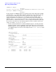
Hardware and Software Installation Procedure Network Configuration Worksheet Network Configuration Worksheet Fill out one worksheet for the networking data of each LAN port on the combination card you are installing. Table 2 Data Type Network Configuration Worksheet Required/ Optional Default How to Configure (see Note 1) Example Internet Address Required 0.0.0.0 SAM or ifconfig or edit /etc/rc.config.d/ netconf 196.6.20.
Hardware and Software Installation Procedure Network Configuration Worksheet Note 3: Following are the valid MTU sizes: • For normal frames using the iether driver on HP-UX 11i v 1.0, the MTU size is a number from 257 to 1500 bytes. On HP-UX 11i v 2.0, the MTU size for normal frames is a number from 1024 to 1500 bytes. • For jumbo frames using the iether driver on HP-UX 11i v 1.0 or HP-UX 11i v 2.0, the MTU size is a number from 1501 to 9000 bytes.
Hardware and Software Installation Procedure Product Overview and Requirements Product Overview and Requirements The AB290A PCI-X Combination cards have the following features and requirements: • PCI-X 133 MHz capable card. It can operate at 32-bit or 64-bit modes and is supported in the following frequencies: PCI 66, PCI-X 66, and PCI-X 133. Best performance is achieved by putting the card in a “dual-rope” PCI-X 133 slot.
Hardware and Software Installation Procedure Interoperability: Supported Systems Interoperability: Supported Systems Supported Systems The combination card is supported in the HP Integrity (Itanium or Itanium2-based) systems specified in Table 3.
Card Physical and Environmental Specs and Regulatory Information Card Physical and Environmental Specifications Card Physical and Environmental Specs and Regulatory Information Card Physical and Environmental Specifications Following are the product physical and environmental specifications of the AB290A PCI-X 2-Port U320 SCSI and 2-Port Gigabit Ethernet Combination Card. Physical Specifications Form Factor PCI-X (2.3) PCI support 64-bit 3.3V only 133Mhz Height 10.8 cm (4.25 in) Depth 21.6 cm (8.
Card Physical and Environmental Specs and Regulatory Information FCC Statement (For U.S.A.) Electromagnetic Compatibility This document contains regulatory statements for the United States and the European community. FCC Statement (For U.S.A.) Federal Communications Commission Radio Frequency Interference Statement WARNING This device complies with Part 15 of the FCC rules.
Card Physical and Environmental Specs and Regulatory Information EMI Statement (European Community) 18