
User's Manual
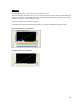
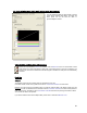
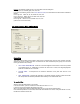
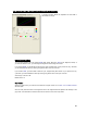
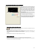
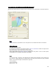
Table Of Contents
- Introduction / Requirements
- Installation
- Login
- Keycode Entry
- Hardware Configuration
- Printers / Queues
- The Configuration Wizard
- Create Queue
- Create Printer Cluster
- Preferences
- Menu Bar Options
- Reprocontrol.client main applications
- Filter Editor
- Functions and Structure of the Filter Editor
- Preview of the Filter Editor
- Histogram
- Tab Black and White Point (Color Mode without Color Management)
- Tab Postprocessing (Black & White Mode)
- Tab Gamma Correction (Color Mode without Color Management)
- Tab Enhancement (Color Mode with Color Management)
- Tab Special Filter (All Modes except of Black & White Mode)
- Tab Color Adjust (Color Mode with Color Management)
- Tab Color Exchange (Color Mode with Color Management)
- Functions and Structure of the Filter Editor
- Reprocontrol.WinDriver
- Reprocontrol.monitor
- Costtracker
- Reprocontrol.backup
64
Example: the following values are set in the entry fields under the histogram:
Black (left) 30, 30, 30 White (right): 230, 230, 230
If you enter the following values under TEXT/BACKGROUND, the aforementioned values will be modified as
follows:
Left 0, right 100 Black: 30, 30, 30, White: 230, 230, 230
Left 10, right 100 Black: 50, 50, 50, White: 230, 230, 230
(values under 50 become black)
Left 0, right 90 Black: 30, 30, 30, White: 210, 210, 210
(values over 210 become white)
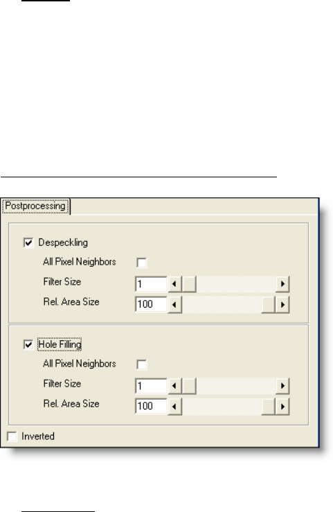
Tab Postprocessing (Black & White Mode)
Despeckling
This option removes black pixels in black & white mode, for example from scans of murky originals. The filter
searches for groups of black pixels and converts them into white. Small-sized pixel groups, such as those
forming punctuation dots, are kept.
ALL
PIXEL NEIGHBORS - Pixels are connected neighbors when there is a series of 8 (instead
of 4) adjacent pixels, i.e. additionally to pixels of the same row or column, the diagonally-adjacent
pixels are considered to be connected.
FILTER
SIZE – It corresponds to the maximum "diameter" of the pixel area which is to be
removed.
REL.
AREA SIZE – This limits the proportion of the actual maximum number of pixels to the filter
size. 0 represents the smallest possible surface relatively to the selected filter size.
To use this filter:
Select an ar
ea with black pixels in the preview.
In the zoom window, open the context menu and select the view 2:1 or 4:1.
In this view, the removed pixels will appear in light gray.
When you make settings with the despeckling filter, be sure not to remove small elements.
If the unwanted pixels form a round area, set the filter size between 70%-100%. If the pixels stretch on a line,
the filter size should lie under 70%.