
Hardware Reference Manual
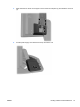
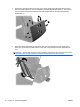
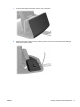
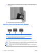
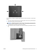
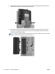
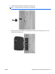
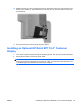
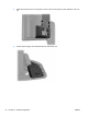
Table Of Contents
- Product Features
- Hardware Upgrades
- Tools Needed
- Warnings and Cautions
- Mounting the RP7 to a Wall or Swing Arm
- Installing the RP7 Adjustable Stand
- Routing Cables to External Devices
- Installing Optional Integrated USB Modules
- Installing an Optional HP Retail RP7 10.4” Customer Display
- Installing an Optional HP Retail RP7 VFD Customer Display
- Installing Additional Memory
- Removing and Installing a Hard Drive
- Replacing the Battery
- Using the USB Security Cover
- Securing the RP7 to a Counter Top
- Installing an External Security Lock
- Configuring the Software
- Troubleshooting
- Electrostatic Discharge
- Computer Operating Guidelines, Routine Care and Shipping Preparation
- Index
9. Replace the rear I/O cover by placing the hooks on the bottom of the cover into the slots on the
bottom of the chassis (1). Then rotate the top of the I/O cover up so that it snaps securely onto
the chassis (2).
10. Reconnect the power cord and press the power button.
Installing Optional Integrated USB Modules
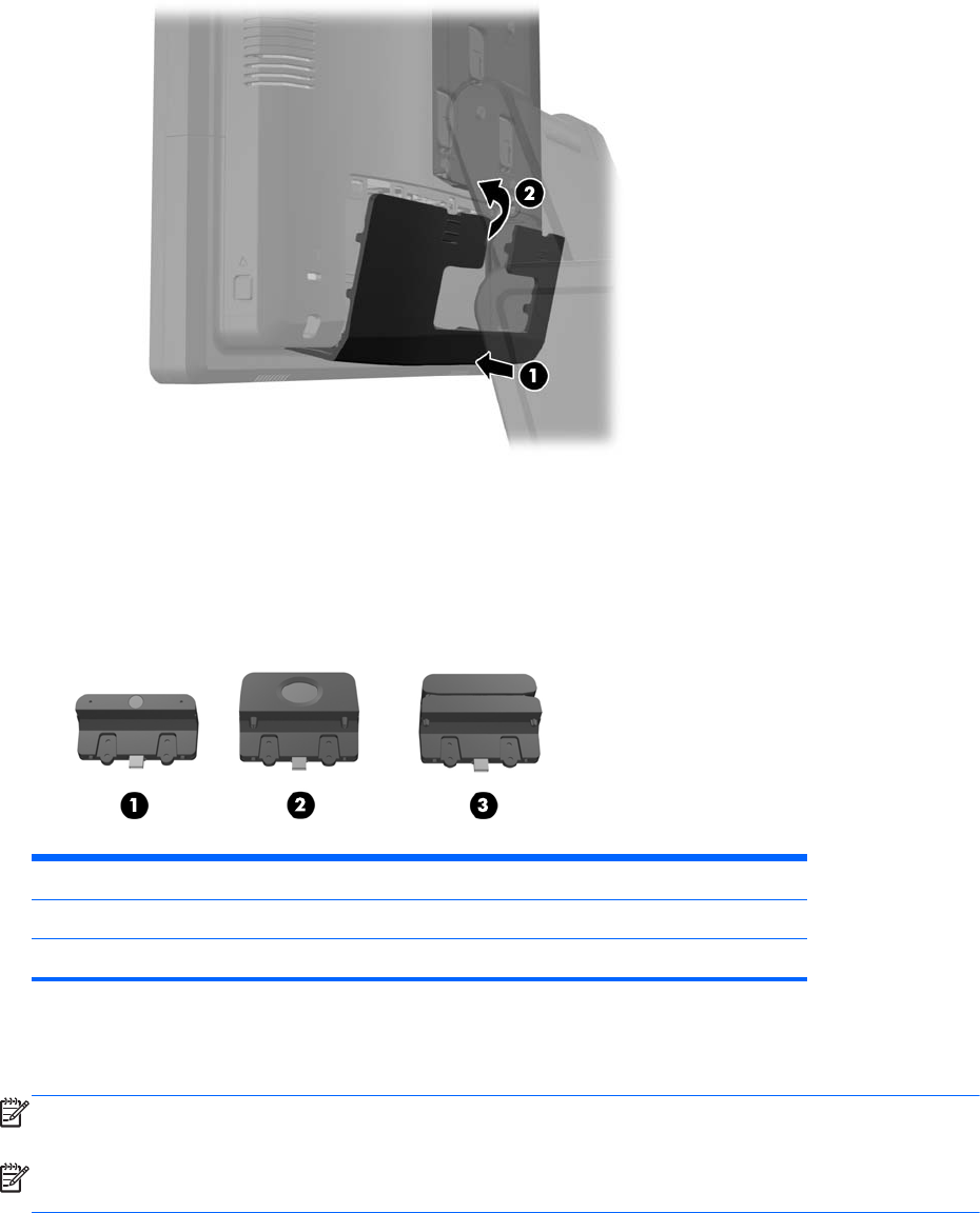
There are three optional integrated USB modules available from HP (sold separately).
1 retail integrated webcam for live video functions
2 retail integrated fingerprint reader to add security identification functions
3 retail integrated dual-head magnetic stripe reader for card data read
The integrated USB modules can be installed on the top of the display head or on either side of the
display head.
NOTE: If you are installing a webcam, do not install it on the sides of the display head. The webcam
must be installed on top of the display head for proper video orientation.
NOTE: These USB ports only support the USB modules listed above. They do not support optical
drives or hard drives.
18 Chapter 2 Hardware Upgrades ENWW