
Hardware Reference Manual
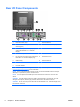
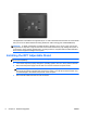
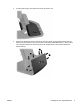
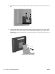
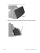
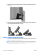
Table Of Contents
- Product Features
- Hardware Upgrades
- Tools Needed
- Warnings and Cautions
- Mounting the RP7 to a Wall or Swing Arm
- Installing the RP7 Adjustable Stand
- Routing Cables to External Devices
- Installing Optional Integrated USB Modules
- Installing an Optional HP Retail RP7 10.4” Customer Display
- Installing an Optional HP Retail RP7 VFD Customer Display
- Installing Additional Memory
- Removing and Installing a Hard Drive
- Replacing the Battery
- Using the USB Security Cover
- Securing the RP7 to a Counter Top
- Installing an External Security Lock
- Configuring the Software
- Troubleshooting
- Electrostatic Discharge
- Computer Operating Guidelines, Routine Care and Shipping Preparation
- Index
This apparatus is intended to be supported by UL or CSA Listed wall mount bracket. HP recommends
that you use an HP Quick Release mounting bracket for wall mounting (part number EM870AA).
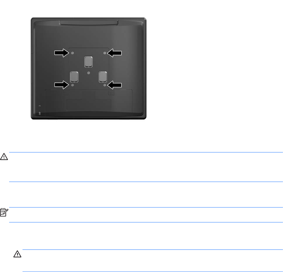
CAUTION: To attach a third-party mounting solution to the RP7, four 4 mm, 0.7 pitch, and 10 mm
long screws are required. Longer screws must not be used because they may damage the system. It
is important to verify that the manufacturer’s mounting solution is compliant with the VESA standard
and is rated to support the weight of the system.
Installing the RP7 Adjustable Stand
NOTE: This section provides instructions for installing the RP7 Adjustable Stand if the stand was
purchased separately.
1. Turn off the computer properly through the operating system, then turn off any external devices.
2. Disconnect the power supply from the rear I/O connector and from the power outlet.
CAUTION: Regardless of the power-on state, voltage is always present on the system board
as long as the system is plugged into an active AC outlet. You must disconnect the power cord
to avoid damage to the internal components of the computer.
3. Disconnect all cables from the rear I/O connectors.
8 Chapter 2 Hardware Upgrades ENWW