Fibre Channel Troubleshooting Guide Sixth Edition (January 2000) Part Number 297877-006 Compaq Computer Corporation
Notice The information in this publication is subject to change without notice. COMPAQ COMPUTER CORPORATION SHALL NOT BE LIABLE FOR TECHNICAL OR EDITORIAL ERRORS OR OMISSIONS CONTAINED HEREIN, NOR FOR INCIDENTAL OR CONSEQUENTIAL DAMAGES RESULTING FROM THE FURNISHING, PERFORMANCE, OR USE OF THIS MATERIAL.
Contents About This Guide Symbols in Text..........................................................................................................vi Compaq Technician Notes .........................................................................................vi Where to Go for Additional Help ..............................................................................vii Telephone Numbers ..........................................................................................
iv Compaq StorageWorks Fibre Channel Troubleshooting Guide Chapter 2 Fibre Channel Fault Isolation Utility Installing the Utility..................................................................................................2-1 Running the Utility...................................................................................................2-1 Program Displays .....................................................................................................
About This Guide Appendix A Primary and Secondary Storage System LEDs Fibre Channel Host Bus Adapters ...........................................................................A-1 RA4000 Controller ..................................................................................................A-2 Storage Hub 7..........................................................................................................A-3 Storage Hub 12.........................................................................
About This Guide This guide is designed to be used as step-by-step instructions for installation and as a reference for operation, troubleshooting, and future upgrades. WARNING: To reduce the risk of personal injury from electrical shock and hazardous energy levels, only authorized service technicians should attempt to repair this equipment. Improper repairs could create conditions that are hazardous.
vii Compaq StorageWorks Fibre Channel Troubleshooting Guide WARNING: To reduce the risk of personal injury from electrical shock and hazardous energy levels, do not exceed the level of repair specified in these procedures. Because of the complexity of the individual boards and subassemblies, do not attempt to make repairs at the component level or to make modifications to any printed wiring board. Improper repairs could create conditions that are hazardous.
About This Guide Telephone Numbers For the name of your nearest Compaq Authorized Reseller: ■ In the United States, call 1-800-345-1518 ■ In Canada, call 1-800-263-5868 For Compaq technical support: ■ In the United States and Canada, call 1-800-386-2172 ■ For Compaq technical support phone numbers outside the United States and Canada, visit the Compaq website: http://www.compaq.com.
Chapter 1 Introduction The Compaq StorageWorks Fibre Channel Troubleshooting Guide provides a description of Compaq StorageWorks RAID Array 4000 and 4100 components for primary and Enterprise Backup Solution components for secondary storage systems. It also provides a description of the Compaq Fibre Channel Fault Isolation Utility, the Fibre Channel Diagnostics Utility, and includes detailed troubleshooting flow charts to help isolate problems on a Fibre Channel Arbitrated Loop (FC-AL).
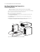
1-2 Compaq StorageWorks Fibre Channel Troubleshooting Guide Fibre Channel Arbitrated Loop Components in a Primary Storage System NOTE: Although RA4000(s) are illustrated throughout this guide, features also apply to RA4100(s).
Introduction Table 1-1 FC-AL Components in a Primary Storage System Reference Component Server RA4000 Rack-Mountable RA4000 (Tower) Fibre Channel Storage Hub 7 GigaBit Interface Converter Compaq StorageWorks RAID Array 4000 System with Redundant Components A Compaq StorageWorks RAID Array 4000 system with redundant components consists of: ■ Two Fibre Channel Host Bus Adapters (PCI only) ■ Two storage hubs (7 or 12) ■ At least one Compaq RA4000 consisting of two RA4000 Controllers and seve
1-4 Compaq StorageWorks Fibre Channel Troubleshooting Guide Table 1-2 Fibre Channel Primary Storage System with Two RA4000s Reference Component RA4000 Controller RA4000 GigaBit Interface Converters Fibre Channel Host Bus Adapter Fibre Channel Storage Hub 7 or 12 Server Fibre Channel Host Bus Adapter/P The Fibre Channel Host Bus Adapter/P is installed in a server with a Peripheral Component Interconnect (PCI) local bus.
Introduction Fibre Channel Host Bus Adapter/E The Fibre Channel Host Bus Adapter/E was designed for use in a server equipped with the EISA expansion bus. The Fibre Channel Host Bus Adapter/E, under the control of the operating system and dedicated device drivers, provides an interface between the EISA bus in the server and a (FC-AL).
1-6 Compaq StorageWorks Fibre Channel Troubleshooting Guide 64-Bit/66-MHz Fibre Channel Host Adapter The 64-Bit/66-MHz Fibre Channel Host Adapter is installed in a server with a PCI local bus and provides an interface between the PCI bus in the server and Fibre Channel-connected external storage systems. The 64-Bit/66-MHz Fibre Channel Host Adapter interface to the server is the Peripheral Component Interconnect (PCI) bus.
Introduction RA4000 Controller The RA4000 Controller is a drive array controller designed to be installed in the Compaq StorageWorks RA4000 and RA4100. The RA4000 Controller supports Fast-SCSI-2, Fast-Wide SCSI-2, or Wide-Ultra SCSI-3 hot-pluggable hard drives. The RA4000 comes equipped with one RA4000 Controller installed. A second RA4000 Controller may be added for a redundant configuration.
1-8 Compaq StorageWorks Fibre Channel Troubleshooting Guide Storage Hub 7 The Compaq Fibre Channel Storage Hub 7 functions as the central point of interconnect for the FC-AL. The Storage Hub 7 has seven I/O ports located on the rear of the unit. Figure 1-7.
Introduction Storage Hub 12 The Storage Hub 12 continuously monitors and automatically configures devices added or removed from the FC-AL. Adding valid FC-AL nodes is a plug-and-play operation. FC-AL nodes that are missing or inoperative are detected, and the data is automatically routed to the next operational port and node on the FC-AL. The Storage Hub 12 is transparent to the data passing through it. It does not consume any FC-AL addresses.
1-10 Compaq StorageWorks Fibre Channel Troubleshooting Guide GigaBit Interface Converter Module (GBIC)-Shortwave (SW) The shortwave GBIC module converts electrical signals to optical serial signals for transmission across the FC-AL and vice versa. The Fibre Channel cable connector is plugged into the installed GBIC module.
Introduction GigaBit Interface Converter Module (GBIC)-Longwave (LW) The longwave GBIC modules must be connected to your server with a single-mode Fibre Channel cable. Only a Fibre Channel test cable is provided with this kit. A list of Fibre Channel cable suppliers can be found at the following website address: http://www.compaq.com/fibrechannel. IMPORTANT: To ensure product integrity, Compaq recommends a 9/125 µm single mode Fibre Channel cable that complies with Bellcore GR409.
1-12 Compaq StorageWorks Fibre Channel Troubleshooting Guide Replacing Components in a Primary Storage System This section describes the steps required to replace FC-AL components in a StorageWorks RAID Array 4000 or 4100 storage system. Refer to the Compaq StorageWorks Fibre Channel Host Bus Adapter Installation Guide and Compaq StorageWorks RAID 4000 User Guide or Compaq StorageWorks RAID 4100 User Guide for details.
Introduction Replacing the RA4000 Controller without RA4000 Redundant Controller When an RA4000 Controller fails in an online RA4000 Array: 1. Perform a normal system shutdown of the servers. 2. Power down the RA4000. 3. Unplug all power cords from the RA4000 Array. Remove the Fibre Channel cable attached to the GBIC in the failed RA4000 Controller. 4. Squeeze the tabs on either side of the GBIC straight out of the RA4000 Controller . , then remove the GBIC by pulling it 2 3 1 2 Figure 1-11.
1-14 Compaq StorageWorks Fibre Channel Troubleshooting Guide 7. Install the replacement RA4000 Controller by inserting it into the tracks in the rear panel opening. 8. Push the controller in as far as it will go and close both latches against the rear panel . The levers on each latch should catch behind the metal lip, drawing the board into position and securing it into place. 2 1 2 Figure 1-13. Installing the RA4000 Controller 9. Replace the GBIC and connect the Fibre Channel cable. 10.
Introduction Replacing the RA4000 Controller with Redundant Controller attached to the GBIC in the failed RA4000 Controller. 2. Squeeze the tabs on either side of the GBIC , then remove the GBIC by pulling it straight out of the RA4000 Controller . 1. Remove the Fibre Channel cable 2 3 1 2 Figure 1-14. Removing the Fibre Channel cable and GBIC 3. Squeeze the latches Controller.
1-16 Compaq StorageWorks Fibre Channel Troubleshooting Guide 4. Remove the RA4000 Controller by pulling it straight out of the chassis . 1 1 2 3 Figure 1-15. Removing the RA4000 Controller 5. Install the replacement RA4000 Controller by inserting it into the tracks in the rear panel opening. 6. Push the controller in as far as it will go and close both latches against the rear panel .
Introduction Fibre Channel Arbitrated Loop Components in a Secondary Storage System A typical Fibre Channel Arbitrated Loop for a secondary storage system consists of: ■ A Fibre Channel Host Bus Adapter installed in each server ■ At least one Storage Hub 12 ■ At least one Fibre Channel Tape Controller ■ One Shortwave GigaBit Interface Converter (GBIC) per Fibre Channel Host Bus Adapter or Storage Hub 12 port. The Fibre Channel Tape Controller has a fixed GLM port and does not require a GBIC.
1-18 Compaq StorageWorks Fibre Channel Troubleshooting Guide The Storage Hub 12 is transparent to the data passing through it. It does not consume any FC-AL addresses. Because of the intelligent signal detection tests, only valid Fibre Channel devices will be connected to the FC-AL. When devices are added to the FC-AL, the Storage Hub 12 will automatically test the new device and accept it into the FC-AL.
Introduction Fibre Channel Tape Controller The Compaq Fibre Channel Tape Controller provides differential SCSI bus connections and a port for connection to the FC-AL. It provides connectivity for a single SCSI Fast/Wide or Ultra SCSI bus running the SCSI Fibre Channel Protocol (FCP). The form factor is 1U (1.7 inches high) and is intended for a standard Compaq Rack System environment. All connections are on the rear panel of the unit.
1-20 Compaq StorageWorks Fibre Channel Troubleshooting Guide Fibre Channel Tape Controller II The Compaq StorageWorks Fibre Channel Tape Controller II (FCTC-II) is a 1U (1.7-inch tall) Fibre Channel-to-SCSI bridge that allows a differential SCSI tape device to communicate with other devices over a Fibre Channel. The tape controller is designed to work as part of an Enterprise Backup Solution. Figure 1-20.
Introduction GigaBit Interface Converter Module-Shortwave This section contains information on the GigaBit Interface Converter Module-Shortwave. See page 1-10 of this guide. Fibre Channel Cable Option Kits This section contains information on the Fibre Channel Cable Option Kits. See page 1-11 of this guide. Replacing Components in a Secondary Storage System This section describes the steps required to replace devices connected to the Fibre Channel Arbitrated Loop (FC-AL).
1-22 Compaq StorageWorks Fibre Channel Troubleshooting Guide Replacing a GBIC To replace a GBIC: 1. Remove the Fibre Channel cable from the failed GBIC. Carefully remove the GBIC from the receptacle on the equipment. 2. Install a known good GBIC into the receptacle on the equipment. The GBIC can only be installed one way because the GBIC and the guide rails inside the Fibre Channel Host Bus Adapter receptacle are keyed. 3. Install the Fibre Channel cable connector into the receptacle on the GBIC.
Chapter 2 Fibre Channel Fault Isolation Utility The Fibre Channel Fault Isolation Utility (FFIU) verifies the integrity of a new or existing FCAL installation. When used with troubleshooting flow charts, this utility provides fault detection and help in locating a failing device on the FC-AL. Each device on the FC-AL has an Arbitrated Loop Physical Address (ALPA). The ALPA is allocated dynamicallyit can change with each power-up or as new devices are added to the loop.
2-2 Compaq StorageWorks Fibre Channel Troubleshooting Guide Program Displays The utility's main display is shown below. It displays each FC-AL from the perspective of the server. All Fibre Host Bus Adapters in the server are shown with a slot number and indicate a PCI (/P) or EISA (/E). NOTE: The Enterprise Backup Solution only supports PCI Host Bus Adapters to ensure adequate performance.
Fibre Channel Fault Isolation Utility Display of a Fibre Channel Tape Controller The Fibre Channel Fault Isolation Utility displays detailed information about any Fibre Channel Tape Controller connected to the FC-AL. The figure below shows a Fibre Channel Tape Controller selected, with detailed information about this tape controller displayed to the right. A Fibre Channel Array Controller is also shown on a separate FC-AL. Figure 2-2.
2-4 Compaq StorageWorks Fibre Channel Troubleshooting Guide Loop Error Histogram Display The Loop Error Histogram indicates errors detected on the FC-AL when a Fibre Channel Host Bus Adapter is highlighted. Each bar represents a 3 second period of activity. The histogram scrolls from right to left. The figure below shows a single error period. Notice that FC-AL errors do not update the histogram unless a Fibre Channel Host Bus Adapter is highlighted.
Fibre Channel Fault Isolation Utility Display of a FC-AL with a Missing Fibre Channel Tape Controller The figure below shows a Fibre Channel Host Bus Adapter highlighted with a Fibre Channel Tape Controller missing. This indicates that while the Tape Controller has become inactive on the FC-AL since the utility was started. This could mean that it has been physically disconnected or that errors are occurring on the FC-AL at a great enough frequency to prevent the device from maintaining login.
2-6 Compaq StorageWorks Fibre Channel Troubleshooting Guide Uninitialized Fibre Channel Arbitrated Loop Display In the figure below, the FC-AL connected to the Fibre Channel Host Bus Adapter in Slot 1 has not initialized. This can be derived from the Fibre Channel Host Bus Adapter having the default ALPA of 255. If this controller was already initialized as part of an FC-AL, it would have a valid ALPA. Figure 2-5.
Chapter 3 Diagnostics Compaq Fibre Channel Diagnostics for Windows CE The Compaq Fibre Channel Diagnostics for Windows CE is a group of hardware diagnostic tests designed to test the RA4000 Controller. It executes on the Windows CE operating system. The test configuration uses a serial cable connected from the handheld computer to the RA4000 Controller. It takes advantage of the built-in self test on the array controller to determine what subsystem is failing.
3-2 Compaq StorageWorks Fibre Channel Troubleshooting Guide Compaq Fibre Channel Backup Diagnostics for Windows NT The Compaq Fibre Channel Diagnostics is a group of hardware diagnostic tests designed to the Compaq StorageWorks Enterprise Backup Solution. This is a subset of the normal Compaq Diagnostics for Windows NT specifically to help identify any potential problems with the Fibre Channel Tape Controller and the DLT 15 Cartridge Library Model 3570 on the Fibre Channel Arbitrated Loop.
Diagnostics ■ ■ Tape Drive Test Unit Ready: queries the changer to see if a good status is returned Buffer Test: writes and reads from the tape drive's onboard cache Firmware Upgrade: will upgrade the firmware of the tape drive FCTC Firmware Upgrade: will upgrade the firmware of the FCTC and the FCTC II Installing Compaq Fibre Channel Diagnostics for Windows CE Compaq Fibre Channel Diagnostics for Windows CE is available on the SmartStart and Support Software CD.
3-4 Compaq StorageWorks Fibre Channel Troubleshooting Guide Installing Compaq Fibre Channel Diagnostics for Windows 95 or 98 Compaq Fibre Channel Diagnostics for Windows 95/98 is available on the SmartStart and Support Software CD. Create the installation diskettes by following the SmartStart instructions. To install the utility: 1. Remove all previous versions of Compaq Diagnostics for Windows 95/98. a. Select Start, Settings, Control Panel. b. Select Add/Remove Programs. c.
Chapter 4 StorageWorks RAID Array 4000 and 4100 Troubleshooting Flow Charts This chapter contains troubleshooting flow charts that will help diagnose problems on a FC-AL in an RA4000 and RA4100 Storage System.
4-2 Compaq StorgeWorks Fibre Channel Troubleshooting Guide Overview of the Troubleshooting Flow Charts The following overview of the Fibre Channel Troubleshooting Flow Charts provides a logical approach to troubleshooting problems on the FC-AL. The Fibre Channel Fault Isolation Utility and the appropriate flow chart can be used to help identify problem areas on the FC-AL and to help verify that the FC-AL is functioning normally after repairs are made.
StorageWorks RAID Array 4000 and 4100 Troubleshooting Flow Charts A Use the Determining A Bad Link flow chart When using the Fibre Channel Fault Isolation Utility, were all Fibre Channel Array Controllers missing? Yes Use the Checking the Link between the Storage Hub 7 and the Fibre Channel Host Bus Adapter flow chart Yes Use the Some Fibre Channel Array Controllers Are Detected flow chart Yes Use the Checking the Link between the Storage Hub 7 and the Fibre Channel Array Controller flow chart No
4-4 Compaq StorgeWorks Fibre Channel Troubleshooting Guide Verify System Operation Begin Ensure that each Host Bus Adapter is fully seated. Verify that power has been applied to all devices on the FC-AL Run System Configuration. No Start the Fibre Channel Fault Isolation Utility at the server. Check again with the Fault Isolation Utility.
StorageWorks RAID Array 4000 and 4100 Troubleshooting Flow Charts B Note: Loop errors may occur briefly as a result of starting the Fault Isolation Utility or adding or removing Fibre Channel Array Controllers. This is normal.
4-6 Compaq StorgeWorks Fibre Channel Troubleshooting Guide Determine a Bad Link Begin Were FC-AL errors detected? No No Done Are Fibre Channel Array Controllers missing? Yes Determine which loop has the errors by highlighting one Host Bus Adapter at a time and looking at the Error Histogram. Are all Fibre Channel Array Controllers missing on a particular FC-AL? Once the FC-AL is determined find the failing device by unplugging one device at a time from the Fibre Storage Hub 7.
StorageWorks RAID Array 4000 and 4100 Troubleshooting Flow Charts Some Fibre Channel Array Controllers Are Detected Begin Run the Fault Isolation utility. Determine which ALPAs are not shown by the utility. Is the Active LED blinking on the Fibre Channel Array Controller not returning an ALPA? See Appendix A for the location of the LED. Yes C No Check seating of the Fibre Channel Array Controller. Check to make sure the power supply is secure and the power source is active.
4-8 Compaq StorgeWorks Fibre Channel Troubleshooting Guide C Is the recieve LED on? No Remove the server cable connector from the GBIC at the Storage Hub 7. Yes Is the transmit LED on? Is the laser light coming from the cable connector? No To check if light is coming from the cable connector, plug the cable into a good GBIC at the Fibre Storage Hub 7 and make sure the Bypass LED goes off. Never look into the connector to see if light is present. No Check the GBIC and the Storage Hub 7.
StorageWorks RAID Array 4000 and 4100 Troubleshooting Flow Charts 4-9 C1 Are the active LEDs lit on the Storage Hub 7? See Appendix A. No Is the GBIC seated properly in the receptacle? Reset the GBIC. No Yes Yes Replace the GBIC. if the problem persists replace the storage Hub 7. Are any Bypass LEDs lit on the Storage Hub 7 that have GBICs and cables installed? See Appendix A. No Did the utility program respond with an ALPA? Yes Yes Verify that power is applied to all devices on the loop.
4-10 Compaq StorgeWorks Fibre Channel Troubleshooting Guide Visual and Physical Inspection of the FC_AL Begin Check the seating of all GBICs and cable connectors on the FC-AL. Has the problem with the FCAL been corrected? No Remove each GBIC and check visually for any defects. Replace GBICs and make sure each GBIC is snapped fully into the connector. The GBIC is keyed to fit only one way.
StorageWorks RAID Array 4000 and 4100 Troubleshooting Flow Charts D Check that cable connector is inserted into GBIC correctly. The cable connector ferrules must be inserted fully into the connector and not recessed. Check with the Fault Isolation Utility to see if the problem was corrected.
4-12 Compaq StorgeWorks Fibre Channel Troubleshooting Guide Checking the Link Between the Storage Hub and the Fibre Channel Array Controller Begin Perform a visual and physical inspection of the FC-AL. Use the Visual and Physical inspection of the FC-AL flow chart. Insert the loopback plug into the GBIC at the Fibre Channel Array Controller and run loop back test. Go to the Fibre Channel Loopback Test flow chart.
StorageWorks RAID Array 4000 and 4100 Troubleshooting Flow Charts E Run the loopback test on this GBIC. Go to the Fibre Channel Loopback Test flow chart. Did the loopback test fail with an internal error message? Yes Possible Fibre Channel Array failure. Check seating of the Fibre Channel Array Controller. Check to make sure the power supply is secure and the power source is active Yes Possible Fibre Channel Array failure. Check seating of the Fibre Channel Array Controller.
4-14 Compaq StorgeWorks Fibre Channel Troubleshooting Guide E1 Attach loopback plug to the cable. Run the loopback test with this cable configuration. Go to the Fibre Channel Loopback Test flow chart. Did the loopback test fail with an external error message? Yes Replace the Fibre Channel cable.
StorageWorks RAID Array 4000 and 4100 Troubleshooting Flow Charts Checking the Link Between the Storage Hub and the Fibre Channel Host Bus Adapter Begin Perform a visual and physical inspection of the FC-AL. Use the Flow Chart on page 4-10 To test the GBICs and the Fibre Channel cable, remove the GBICs and the cable from between the Fibre Channel Host Bus Adapter and the Storage Hub 7 or Hub 12.
4-16 Compaq StorgeWorks Fibre Channel Troubleshooting Guide F Remove the GBIC from the other end of the cable. Place loopback plug on the end of the cable. Run the Fault Isolation Utility Observe the program display for errors. Were there errors? No If the problem persists, try new components or seek Compaq Service Yes Done Possible Fibre Channel Host Bus Adapter failure.
StorageWorks RAID Array 4000 and 4100 Troubleshooting Flow Charts Fibre Channel Loopback Test Begin The Fibre Channel Loopback test is a method to verify proper function of cables, GBICs and nodes of your Fibre Array system on an isolated link. The test consists of running a diagnostic utility remotely through a serial port connection between the Fibre Array and a PC such as a laptop. To isolate the link, a loopback plug is used to close the circuit.
4-18 Compaq StorgeWorks Fibre Channel Troubleshooting Guide G Did the test pass? No Yes Insert the Fibre Channel cable into the GBIC at the Fibre Array. Insert the Loopback plug into the connector of the Fibre Channel cable. Run the diagnostics utility on the laptop or other computer.
StorageWorks RAID Array 4000 and 4100 Troubleshooting Flow Charts G1 Yes GBIC not plugged-in error? Reseat the GBIC. Return to page 4-17 to begin the Fibre Channel Loopback Test flowchart again. No Yes Internal failure indicated? Replace the Fibre Channel Array Controller. No Done External failure indicated? No Yes Replace the GBIC or Fibre Channel Cable, depending on which was being tested.
Chapter 5 Secondary Storage System Troubleshooting Flow Charts This chapter contains troubleshooting flow charts that can be used to diagnose problems on a FC-AL in a Secondary Storage System.
5-2 Compaq StorageWorks Fibre Channel Troubleshooting Guide Overview of the Troubleshooting Flow Charts The following overview of the Fibre Channel Troubleshooting Flow Charts provides a logical approach to troubleshooting problems on the FC-AL. The Fibre Channel Fault Isolation Utility and the appropriate flow chart can be used to help identify problem areas on the FC-AL and to help verify that the FC-AL is functioning normally after repairs are made.
Secondary Storage System Troubleshooting Flow Charts A Run the Fibre Channel Fault Isolation Utility. Were all Fibre Channel Tape Controllers missing? Yes Use the Checking the Link between the Storage Hub 12 and the Fibre Host Bus Adapter flow chart. Yes Use the Some Fibre Channel Tape Controllers Are Detected flow chart. Yes Use the Checking the Link between the Storage Hub 12 and the Fibre Channel Tape Controller flow chart.
5-4 Compaq StorageWorks Fibre Channel Troubleshooting Guide Verifying FC_AL Operation Begin Verify that power has been applied to all devices on the FC-AL. Ensure that each Host Bus Adapter is fully seated. Run System Configuration Utility. No Start the Fibre Channel Fault Isolation Utility at the server. Check again with the Fault Isolation Utility.
Secondary Storage System Troubleshooting Flow Charts B Note: Loop errors may occur briefly as a result of starting the Fault Isolation Utility or adding or removing Fibre Channel Tape Controllers. This is normal. Highlight a server in the Fault Isolation Utility. Any errors in Error Histogram? Yes No Go to Determining a Bad Link flow chart.
5-6 Compaq StorageWorks Fibre Channel Troubleshooting Guide Determining a Bad Link Begin Were FC-AL errors detected? No No Are Fibre Channel Tape Controllers Missing? Yes Yes Determine which loop has the errors by highlighting one Host Controller at a time and looking at the Error Histogram. Are all Fibre Channel Tape Controllers missing on a particular FC-AL? Once the FC-AL is determined find the failing device by unplugging one device at a time from the Fibre Storage Hub 12.
Secondary Storage System Troubleshooting Flow Charts Some Fibre Channel Tape Controllers are Detected Begin Run the Fault Isolation utility. Determine which ALPAs are not shown by the utility. Is the missing Tape Controller connected to a FC-AL shared with other Tape Controllers? Yes B1 No Go to the Checking the Link between the Fibre Storage Hub 12 and the Fibre Channel Host Bus Adapter flow chart.
5-8 Compaq StorageWorks Fibre Channel Troubleshooting Guide B1 Are any Bypass LEDs (Amber) lit on the Storage Hub 12? Refer to Appendix A for the location of the LED. No Is the Fibre Channel LED flickering on the Fibre Channel Tape Controller? Refer to Appendix A for the location of the LED. Yes Possible Fibre Channel Storage Hub 12 failure. Run Fibre Channel Storage Hub 12 diagnostics. Refer to the Fibre Channel Storage Hub 12 Installation Guide for details.
Secondary Storage System Troubleshooting Flow Charts Visual and Physical Inspection of the FC_AL Begin Check the seating of all GBICs and cable connectors on the FC-AL. Is the FC-AL functioning normally? No Remove each GBIC and check visually for any defects. Replace GBICs and make sure each GBIC is snapped fully into the connector. The GBIC is keyed to fit only one way.
5-10 Compaq StorageWorks Fibre Channel Troubleshooting Guide C1 Verify the Cable connector is inserted into GBIC correctly. The cable connector ferrules must be inserted fully into the connector and not recessed. Check the FC-AL with the Fibre Channel Fault Isolation Utility to see if the problem was corrected.
Secondary Storage System Troubleshooting Flow Charts Checking the Link Between the Storage Hub 12 and the Fibre Channel Host Bus Adapter Begin Perform a visual and physical inspection of the FC-AL. Use the flow chart on page 5-9. To troubleshoot the GBICs and cable between the Storage Hub 12 and Fibre Channel Host Bus Adapter, replace them with new components. Once the replacement is made, verify system performance with the Fault Isolation Utility.
5-12 Compaq StorageWorks Fibre Channel Troubleshooting Guide D1 Place loopback plug, with crossover, on the end of the cable. Run the Fault Isolation Utility. Observe the program display for errors. Were there any errors? No If the problem persists, try new components or seek Compaq Service.
Secondary Storage System Troubleshooting Flow Charts Checking the Link Between the Storage Hub 12 and the Fibre Channel Tape Controller Begin Perform a visual and physical inspection of the FC-AL. Use the flow chart on page 5-9. Run the Fault Isolation Utility to test the integrity of the link. Replace the GBIC or the cable and run the Fault Isolation Utility to see if the problem still exists. Is the FC-AL functioning normally? No Connect a cable to the Fibre Channel Tape Controller.
5-14 Compaq StorageWorks Fibre Channel Troubleshooting Guide E1 Is laser light coming from the cable connector? No Possible Tape Controller failure. Refer to the Compaq Fibre Channel Tape Controller User Guide for additional troubleshooting information. Yes Replace the GBIC at the Storage Hub 12. Were there any errors? Yes If the problem persists, try new components or seek Compaq Service.
Appendix A Primary and Secondary Storage System LEDs This section describes the LEDs found in a Compaq StorageWorks RA4000, RA4100, or Enterprise Backup Solution. The LEDs described in this Appendix can be used to determine normal operation or fault conditions depending on their assignment. Fibre Channel Host Bus Adapters Transmit LED Receive LED Figure A-1.
A-2 Fibre Channel Troubleshooting Guide Receive LED Transmit LED Figure A-2. Fibre Channel Host Bus Adapter/E RA4000 Controller During normal operation, the RA4000 Controller has 18 LEDs that indicate activity or status of the controller. Table A-1 describes the purpose and function of each LED. GBIC Receptacle Transmit LED Serial Debug Port 1514 1312 1110 9 8 7 6 5 4 3 2 1 0 Receive LED Figure A-3.
Primary and Secondary Storage System LEDs Table A-1 RA4000 Controller LED Descriptions continued LED Function Description 13 SCSI Bus 1 Active On = Indicates requests are outstanding on the second SCSI bus 14 Cache Activity/Error On = Cache Failure Off = No Cache activity Blinking = Cache transfer pending 15 Drive Failure On = A configured hard drive has failed in the array Transmit LED Transmit Mode RA4000 Controller is transmitting data over the FC-AL Receive LED Receive Mode RA4000 Cont
A-4 Fibre Channel Troubleshooting Guide Figure A-5. Bypass Mode LEDs Storage Hub 12 When power is applied, all LEDs will turn on during the self-test, which lasts 15 to 60 seconds. After the power self test, the Power LED stays on, the Fault LED turns off. Figure A-6 shows the location of the Power and Fault LEDs. Fault r Powe Figure A-6.
Primary and Secondary Storage System LEDs The upper green LED is the GBIC-installed LED. This LED turns on when a GBIC module is installed. 2 G B Figure A-7. GBIC-Installed LED The lower amber LED is the Bypass Port LED, which indicates that the associated port is in bypass mode. Ports that do not detect valid FC-AL links will be placed in bypass mode by the hub. The LED is turned on for each port, in the bypass mode. 3 G B Figure A-8.
A-6 Fibre Channel Troubleshooting Guide Fibre Channel Tape Controller Figure A-9 shows the location of the LEDs found on the rear panel of the Fibre Channel tape controller. 3 1 4 2 5 Figure A-9.
Primary and Secondary Storage System LEDs Fibre Channel Tape Controller II The following illustration shows the location of the status lights (LED indicators) that monitor the operating status of the Compaq StorageWorks Fibre Channel Tape Controller II. 3 1 4 2 5 6 Figure A-10.
Appendix B GBIC and Fibre Channel Cable Connector Cleaning Considerations This appendix contains important information about the risk of optic contamination of both GBIC modules and Fibre Channel cable connectors. Optics are susceptible to anything that hinders light transmission. Consequently, manufacturers of both GBIC Modules and Fibre Channel cable connectors provide dust covers to protect the optical areas and ensure optical signal integrity for initial system configuration.
Index A D ALPA See Arbitrated Loop Physical Address Arbitrated Loop Physical Address 2-1, 2-2 defined, GBIC modules 1-6 determine a bad link primary storage flow chart 4-6 secondary storage system flowchart 5-6 Diagnostics Installation 3-3 Windows 95/98 3-1 Windows CE 3-1 Dust Covers B-1 B bridge 1-20 C Cable option kits 1-11 cables connecting 1-14, 1-16 removing 1-13, 1-15 chassis 1-13, 1-16 Checking the Link Between the Storage Hub 12 and the Fibre Channel Tape Controller secondary storage system fl
2 Compaq StorageWorks Fibre Channel Troubleshooting Guide FFIU See Fibre Channel Fault Isolation Utility Fiber Channel Tape Controller II description 1-20 Fibre Channel Arbitrated Loop See FC_AL shown unitialized 2-6 Fibre Channel cable option kits description 1-11 Fibre Channel Disk Array Controller 2-3 Fibre Channel Fault Isolation Utility information and updates 2-6 installing 2-1 main display 2-2 program displays 2-2 purpose 2-1 Fibre Channel Fault Isolation Utility: 2-1 Fibre Channel Host Adapter 64-
Index figures installing the RA4000 Controller 1-14, 1-16 removing the RA4000 Controller 1-13, 1-16 flow charts primary system checking link between hub and array controller 4-12 checking link between hub and host bus adapter 4-15 determine bad link 4-6 Fibre Channel Array Controllers detected 4-7 fibre channel loopback test 4-17 overview 4-2 verify system operation 4-4 visual inspection of FC_AL 4-10 secondary system checking link between hub and fibre channel tape controller 5-13 checking link between hu
4 Compaq StorageWorks Fibre Channel Troubleshooting Guide P panels rear 1-14 PCI (/P) 2-2 bus 1-4 Host Bus Adapter 2-2 PCI bus See PCI PLDA 1-20 power status light A-7 primary storage flow chart overview 4-2 some Fibre Array Controllers are detected 4-7 verify system operation 4-4 primary storage flow charts determine a bad link 4-6 primary storage flowchart Fibre Channel Loopback test 4-17 Private Loop Direct Attach 1-20 R RA4000 description 1-7 powering up 1-14 system component 1-2 RA4000 Controller ej
Index V W verify system operation primary storage flow chart 4-4 When to Clean Fiber Optic Components B-1 www.compaq.