HP ProLiant WS460c Gen8 Graphics Server Blade and Expansion Blade User Guide Abstract This guide provides operation information for the HP ProLiant WS460c Gen8 Graphics Server Blade and Expansion Blade. This guide is for technicians that install, administer, and troubleshoot servers and storage systems.
© Copyright 2012, 2014 Hewlett-Packard Development Company, L.P. The information contained herein is subject to change without notice. The only warranties for HP products and services are set forth in the express warranty statements accompanying such products and services. Nothing herein should be construed as constituting an additional warranty. HP shall not be liable for technical or editorial errors or omissions contained herein. Microsoft®, Windows®, and Windows Server® are U.S.
Contents Component identification ............................................................................................................... 6 Front panel components ............................................................................................................................. 6 Front panel components for workstation blade with graphics expansion blade .................................................. 7 Front panel LEDs and buttons ........................................................
Memory options ...................................................................................................................................... 47 HP SmartMemory .......................................................................................................................... 48 Memory subsystem architecture ....................................................................................................... 48 Single-, dual-, and quad-rank DIMMs .............................................
HP Technology Service Portfolio ...................................................................................................... 78 Change control and proactive notification ........................................................................................ 79 Battery replacement .................................................................................................................... 80 Regulatory information ............................................................................
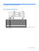
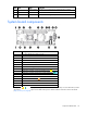
Component identification Front panel components Item Description 1 Hard drive bay 1 2 Server blade release button 3 Server blade release lever 4 Hard drive bay 2 5 HP c-Class Blade SUV connector* (behind the serial label pull tab) 6 Serial label pull tab *The SUV connector and the HP c-Class Blade SUV Cable are used for some workstation blade configuration and diagnostic procedures.
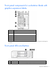
Front panel components for workstation blade with graphics expansion blade Item Description 1 Serial label pull tab 2 HP c-Class Blade SUV connector* (behind the serial label pull tab) 3 Drive bay 2 4 Drive bay 1 5 Server blade release lever 6 Server blade release button * The SUV connector and the HP c-Class SUV Cable are used for some server blade configuration and diagnostic procedures.
Item Description bar Status Flashing Green = Power On/Standby button service is being initialized Flashing Amber = Degraded condition Flashing Red = Critical condition Off = Normal (System is in standby) 2 Power On/Standby Solid Green = System is powered on. button and system Flashing Green = System is waiting to power on; Power On/Standby button is power LED pressed. Solid Amber = System is in standby; Power On/Standby button service is initialized.
Item Description Status power LED pressed. Solid Amber = System is in standby; Power On/Standby button service is initialized. Off and the Health Status LED bar is off = The system has no power. Off and the Health Status LED bar is flashing green = The Power On/Standby button service is being initialized.
Item LED Status Definition Flashing amber The drive is not configured and predicts the drive will fail. Solid amber The drive has failed. Off The drive is not configured by a RAID controller.
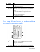
System maintenance switch Position Default Function S1 Off Off = iLO 4 security is enabled. On = iLO 4 security is disabled. S2 Off Off = System configuration can be changed. On = System configuration is locked. S3 Off Reserved S4 Off Reserved S5 Off Off = Power-on password is enabled. On = Power-on password is disabled. S6 Off Off = No function On = ROM reads system configuration as invalid.
The arrow points to the front of the workstation blade. DIMM tool location The DIMM tool is used to open and close an empty DIMM slot.
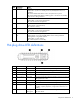
Item Connector Description 2 Video For connecting a video monitor 3 USB For connecting up to two USB devices 4 Serial For trained personnel to connect a null modem serial cable and perform advanced diagnostic procedures Component identification 13
Operations Power up the workstation blade The Onboard Administrator initiates an automatic power-up sequence when the workstation blade is installed. If the default setting is changed, use one of the following methods to power up the workstation blade: • Use a virtual power button selection through iLO 4. • Press and release the Power On/Standby button. When the workstation blade goes from the standby mode to the full power mode, the system power LED changes from amber to solid green.
This command initiates a controlled shutdown of applications and the OS before the workstation blade enters standby mode. o poweroff server [bay number] force This form of the command forces the workstation blade to enter standby mode without properly exiting applications and the OS. If an application stops responding, this method forces a shutdown. • Use the Onboard Administrator GUI to initiate a shutdown: a. Select the Enclosure Information tab. b.
Remove the access panel 1. Power down the workstation blade (on page 14). 2. Remove the workstation blade (on page 15). 3. If necessary, remove the graphics expansion blade ("Remove the WS460c Graphics Expansion Blade" on page 21, "Remove the WS460c Graphics Expansion Blade PCIe card cage" on page 23). 4. Press the access panel release button. 5. To remove the access panel, slide it towards the rear of the workstation blade, and then lift the panel. Install the access panel 1.
Remove the DIMM baffle 1. Power down the workstation blade (on page 14). 2. Remove the workstation blade (on page 15). 3. Remove the access panel (on page 16). 4. Disconnect the capacitor pack cabling, if connected ("FBWC capacitor pack cabling" on page 64). 5. Remove one or more DIMM baffles.
o DIMM baffle (right side) Remove the SAS controller 1. Power down the workstation blade (on page 14). 2. Remove the workstation blade (on page 15). 3. Remove the access panel (on page 16). 4. Disconnect the capacitor pack cabling, if connected ("FBWC capacitor pack cabling" on page 64). CAUTION: Always remove the SAS controller before removing the drive cage. CAUTION: Always be sure that both captive screws are disengaged before removing the SAS controller.
5. Remove the SAS controller. Install the SAS controller 1. Power down the workstation blade (on page 14). 2. Remove the workstation blade (on page 15). 3. Remove the access panel (on page 16). 4. Disconnect the FBWC battery pack cabling, if connected ("FBWC capacitor pack cabling" on page 64). IMPORTANT: Always close the SAS controller handle before installing the SAS controller.
5. Close the SAS controller handle and then install the SAS controller. To properly seat the SAS controller, press firmly in the areas indicated on the SAS controller. Remove the WS460c Graphics Expansion Blade access panel 1. Power down the workstation blade (on page 14). 2. Remove the workstation blade (on page 15). 3. Lift the access panel latch (1), and then slide the access panel to the rear (2). 4. Remove the access panel.
Remove the WS460c Graphics Expansion Blade 1. Power down the workstation blade (on page 14). 2. Remove the workstation blade. 3. Remove the WS460c Graphics Expansion Blade access panel (on page 20). 4. Remove the screws (1) and the front bezel (2). 5. Remove the gasket. NOTE: A stabilizer/coupler (black) is used when coupling and stabilizing two mezzanine pass-through cards.
pass-through mezzanine card is used. Retain unused stabilizer/coupler for future use with possible configuration changes. 6. Disconnect the power cable from the upper mezzanine card (1), and then disconnect the other end of the power cable (2). 7. Disconnect the signal cable from the lower mezzanine cards: a. Apply pressure to the lower mezzanine card (1), squeeze the latch (2), and then disconnect the signal cable from the lower mezzanine card (3). b. Disconnect the other end of the signal cable (4).
8. Remove the screws (1), slide the graphics expansion blade back, and then lift it up (2) from the workstation blade. Remove the WS460c Graphics Expansion Blade PCIe card cage To remove the component: 1. Power down the workstation blade (on page 14). 2. Remove the workstation blade (on page 15). 3. Remove the WS460c Graphics Expansion Blade access panel (on page 20). 4. Remove the screws and the front bezel.
5. Remove the gasket. 6. Disconnect the power cable from the upper mezzanine card, and then disconnect the other end of the power cable. 7. Disconnect the signal cable from the lower mezzanine card: a. Apply pressure to the lower mezzanine card (1), squeeze the latch (2), and then disconnect the signal cable from the lower mezzanine card (3).
b. Disconnect the other end of the signal cable (4). 8. Remove the retaining block.
9. Remove the anchoring pin from the graphics expansion blade, and then remove the card cage. To reinstall the component, reverse the removal procedure. NOTE: After the reinstalling the pass-through mezzanine cards, ensure DIMMs are seated correctly by pressing down the DIMMs and locking the latch.
6. Remove the graphics card from the bottom slot of the card cage. 7. Install the new graphics card to the bottom slot of the card cage. 8. Install the graphics card cover into the top slot of the card cage, connect any power cables to the graphics card, and then tighten the retaining screws. 9. Reinstall the graphics card retainer, and then reinstall the entire PCIe card cage into the graphics expansion blade chassis. 10. Reconnect the four PCIe/SAS cables. 11.
Install the NVIDIA Quadro K5000 or K6000 graphics card Required tools for this procedure: • T-10/T-15 Torx screwdriver (provided inside the server) • HP Insight Diagnostics software To remove the graphics card from the graphics expansion blade: 1. Power down the workstation blade (on page 14). 2. Remove the workstation blade. 3. Remove the WS460c Graphics Expansion Blade access panel (on page 20). 4. Remove the WS460c Graphics Expansion Blade PCIe card cage (on page 23). 5.
3. Remove the screws and washers. IMPORTANT: Remove the I/O plate from the original NVIDIA GRID K2 card. Before installing the NVIDIA GRID K2 I/O plate on the graphics expansion blade, the GRID K2 card I/O plate must be assembled with the new spare part. IMPORTANT: For NVIDIA GRID K1 installation: Remove the pre-installed I/O plate from the NVIDIA GRID K1 card and replace it with the I/O plate from the original NVIDIA GRID K1 card. 4.
If the screws lack Nylok coating or are used, add Loctite 242 Threadlocker 3~5 threads from the tip. 6. Install M2.5x6 mm wafer head screws (the same screws removed in step 1) through the heat spreader, plate tab, and process control board hole alignment to the baseplate, and then torque both screws to 4.0~4.5 in-lbf. If the screws do not have Nylok coating, or are used, add Loctite 242 Threadlocker 3~5 threads from the tip.
7. Torque both front plate screws to 3.0~3.5 in-lbf. IMPORTANT: Ensure that air flow impedance control labels cover the three openings on each end of the I/O plate. These labels control the air flow into the GRID card and balance the air flow to adjacent blades. Using the card in the expansion blade without implementing this measure might potentially result in unexpected host shutdown of the host blade and/or nearby blades in the same enclosure.
For software installation information, see the Microsoft Windows on HP ProLiant WS460c Gen8 Workstation Blade with WS460c Graphics Expansion Blade Administrator Guide. Install the NVIDIA GRID K1 or K2 graphics card Required tools for this procedure: • T-10/T-15 Torx screwdriver (provided inside the server) • HP Insight Diagnostics software For basic installation instructions, follow these steps. To remove the graphics cards from the graphics expansion blade: 1.
To remove the graphics cards from the graphics expansion blade and install the plate: 1. Power down the workstation blade (on page 14). 2. Remove the workstation blade (on page 15). IMPORTANT: Remove the I/O plate from the original NVIDIA GRID K20/K20X card. Before installing the NVIDIA GRID K20/K20X I/O plate on the graphics expansion blade, the GRID K20/K20X card I/O plate must be assembled with the new spare part.
5. Install M2.5x6 mm wafer head screw through the plate tab and process control board hole alignment to the baseplate, and then torque screw to 4.0~4.5 in-lbf. If the screw does not have Nylok coating, or are used, add Loctite 242 Threadlocker 3~5 threads from the tip.
6. Torque the three front plate screws to 3.0~3.5 in-lbf. IMPORTANT: Ensure that air flow impedance control labels cover the five openings on each end of the I/O plate. These labels control the air flow into the GRID card and balance the air flow to adjacent blades. Using the card in the expansion blade without implementing this measure might potentially result in unexpected host shutdown of the host blade and/or nearby blades in the same enclosure.
• T-10/T-15 Torx screwdriver (provided inside the server) • HP Insight Diagnostics software For basic installation instructions, follow these steps. To remove the graphics cards from the graphics expansion blade: 1. Power down the workstation blade (on page 14). 2. Remove the workstation blade. 3. Remove the WS460c Graphics Expansion Blade access panel (on page 20). 4. Remove the WS460c Graphics Expansion Blade PCIe card cage (on page 23). 5.
Setup Overview Installation of a workstation blade requires the following steps: 1. Install and configure an HP BladeSystem c-Class enclosure. 2. Install any workstation blade options. 3. Install interconnect modules in the enclosure. 4. Connect the interconnect modules to the network. 5. Install a workstation blade. 6. Complete the workstation blade configuration.
Interconnect bay numbering and device mapping • HP BladeSystem c7000 Enclosure To support network connections for specific signals, install an interconnect module in the bay corresponding to the FlexibleLOM or mezzanine signals.
• HP BladeSystem c3000 Enclosure and Tower Enclosure Server blade signal Interconnect bay number Interconnect bay label Notes FlexibleLOM 1 — Mezzanine 1 2 Four port cards connect to bay 2. Mezzanine 2 3 and 4 • • • Four port cards Ports 1 and 3 connect to bay 3. Ports 2 and 4 connect to bay 4.
Two types of interconnect modules are available for HP BladeSystem c-Class enclosures: Pass-Thru modules and switch modules. For more information about interconnect module options, see the HP website (http://www.hp.com/go/bladesystem/interconnects). IMPORTANT: To connect to a network with a Pass-Thru module, always connect the Pass-Thru module to a network device that supports Gigabit or 10 Gb speed, depending on the corresponding Pass-Thru model.
2. Remove the enclosure connector cover. 3. Install the workstation blade. Completing the configuration To complete the workstation blade and HP BladeSystem configuration, see the overview card that ships with the enclosure.
Hardware options installation Introduction If more than one option is being installed, read the installation instructions for all the hardware options and identify similar steps to streamline the installation process. WARNING: To reduce the risk of personal injury from hot surfaces, allow the drives and the internal system components to cool before touching them. CAUTION: To prevent damage to electrical components, properly ground the server before beginning any installation procedure.
3. Install the drive. 4. Determine the status of the drive from the drive LED definitions ("Hot-plug drive LED definitions" on page 9). Processor option WARNING: To reduce the risk of personal injury from hot surfaces, allow the drives and the internal system components to cool before touching them. CAUTION: To prevent possible workstation blade malfunction and damage to the equipment, multiprocessor configurations must contain processors with the same part number.
6. Remove the heatsink blank. Retain the heatsink blank for future use. 7. Open each of the processor locking levers in the order indicated, and then open the processor retaining bracket.
8. Remove the clear processor socket cover. Retain the processor socket cover for future use. 9. Install the processor. Verify that the processor is fully seated in the processor retaining bracket by visually inspecting the processor installation guides on either side of the processor. THE PINS ON THE SYSTEM BOARD ARE VERY FRAGILE AND EASILY DAMAGED. CAUTION: THE PINS ON THE SYSTEM BOARD ARE VERY FRAGILE AND EASILY DAMAGED.
CAUTION: Do not press down on the processor. Pressing down on the processor may cause damage to the processor socket and the system board. Press only in the area indicated on the processor retaining bracket. 11. Press and hold the processor retaining bracket in place, and then close each processor locking lever. Press only in the area indicated on the processor retaining bracket. 12. Remove the thermal interface protective cover from the heatsink.
CAUTION: Heatsink retaining screws should be tightened in diagonally opposite pairs (in an "X" pattern). 13. Install the heatsink. 14. Install the SAS controller (on page 19). 15. Install the access panel (on page 16). 16. Install the workstation blade ("Installing a server blade" on page 40). Memory options IMPORTANT: This workstation blade does not support mixing LRDIMMs, RDIMMs, or UDIMMs. Attempting to mix any combination of these DIMMs can cause the server to halt during BIOS initialization.
• Quad-rank PC3L-10600 (DDR3-1333) LRDIMMs operating at up to 1333 MT/s Speed, voltage, and capacity DIMM type DIMM rank DIMM capacity Native speed (MT/s) Voltage RDIMM Single-rank 4 GB 1600 STD RDIMM Dual-rank 8 GB 1333 LV RDIMM Single-rank 8 GB 1600 STD RDIMM Dual-rank 16 GB 1333 LV RDIMM Dual-rank 16 GB 1600 STD LRDIMM Quad-rank 32 GB 1333 LV UDIMM Single-rank 2 GB 1333 LV UDIMM Dual-rank 4 GB 1333 LV UDIMM Dual-rank 8 GB 1333 LV Depending on the proces
Channel Slot Slot number 1 A E 1 2 2 B F 3 4 3 C G 8 7 4 D H 6 5 For the location of the slot numbers, see "DIMM slot locations (on page 11)." This multi-channel architecture provides enhanced performance in Advanced ECC mode. This architecture also enables the Lockstep memory mode. DIMM slots in this server are identified by number and by letter. Letters identify the population order. Slot numbers indicate the DIMM slot ID for spare replacement.
DIMM identification To determine DIMM characteristics, use the label attached to the DIMM and the following illustration and table. Item Description Definition 1 Size — 2 Rank 1R 2R 3R 4R 3 Data width x4 = 4-bit x8 = 8-bit 4 Voltage rating L = Low voltage (1.35V) U = Ultra low voltage (1.
• Online spare memory—provides protection against failing or degraded DIMMs. Certain memory is reserved as spare, and automatic failover to spare memory occurs when the system detects a DIMM that is degrading. This allows DIMMs that have a higher probability of receiving an uncorrectable memory error (which would result in system downtime) to be removed from operation. Advanced Memory Protection options are configured in RBSU.
the memory contents of the degraded rank to the online spare rank. The workstation blade then deactivates the failing rank and automatically switches over to the online spare rank. Lockstep memory configuration Lockstep mode provides protection against multi-bit memory errors that occur on the same DRAM device. Lockstep mode can correct any single DRAM device failure on x4 and x8 DIMM types. The DIMMs in each channel must have identical HP part numbers.
o LRDIMMs are treated as dual-rank DIMMs. Lockstep Memory population guidelines For Lockstep memory mode configurations, observe the following guidelines: • Observe the general DIMM slot population guidelines (on page 52). • DIMM configuration on all channels of a processor must be identical. • In multi-processor configurations, each processor must have a valid Lockstep Memory configuration.
7. Install the DIMM. 8. Install all DIMM baffles. 9. Install the access panel (on page 16). To configure the memory mode, use RBSU ("HP ROM-Based Setup Utility" on page 72). Mezzanine card option Optional mezzanine cards are classified as Type A mezzanine cards and Type B mezzanine cards. The type of the mezzanine card determines where it can be installed in the workstation blade. • Install Type A mezzanine cards on Mezzanine 1 connector or Mezzanine 2 connector.
4. Remove the mezzanine assembly from the workstation blade. 5. Align the mezzanine card with the guide pins on the mezzanine assembly.
6. Install the mezzanine card in the mezzanine assembly, and then tighten the mezzanine card screws to secure the card to the mezzanine assembly. 7. Align the mezzanine assembly with the guide pins on the system board, and then install the mezzanine assembly on the system board. 8. Press down firmly on the mezzanine assembly handles, and then close the mezzanine assembly latch. 9. Install the access panel (on page 16). 10. Install the workstation blade ("Installing a server blade" on page 40).
IMPORTANT: This procedure is for replacing NVIDIA Quadro 1000M and 3000M graphics cards only on the workstation blade. The procedure for replacing these particular graphics cards on the graphics expansion blade is different, and must be performed by HP service personnel only. Required tools for this procedure: • T-10/T-15 Torx screwdriver (provided inside the server) • HP Insight Diagnostics software The following figure shows the mezzanine connector slots.
To install the mezzanine card: 1. Align the mezzanine card with the guide pins on the mezzanine assembly. 2. Install the mezzanine card in the mezzanine assembly, and then to secure the card to the mezzanine assembly, tighten the mezzanine card screws. The installation is complete. FBWC capacitor pack To install the component: 1. Power down the workstation blade (on page 14). 2. Remove the workstation blade (on page 15). 3. Remove the access panel (on page 16). 4.
5. o FBWC capacitor pack for the SAS controller o FBWC capacitor pack for a mezzanine option. Route the FBWC capacitor pack cable. The DIMM baffles may be removed to route the cables, if necessary.
o Route the cable along the right DIMM baffle and connect the cable to the SAS controller. o Route the cable along the left DIMM baffle and connect the cable to the mezzanine option. 6. Install the access panel (on page 16). 7. Install the workstation blade ("Installing a server blade" on page 40).
When installing or replacing a TPM, observe the following guidelines: • Do not remove an installed TPM. Once installed, the TPM becomes a permanent part of the system board. • When installing or replacing hardware, HP service providers cannot enable the TPM or the encryption technology. For security reasons, only the customer can enable these features. • When returning a system board for service replacement, do not remove the TPM from the system board.
9. Install the TPM board. Press down on the connector to seat the board ("System board components" on page 10). 10. Install the TPM security rivet by pressing the rivet firmly into the system board. 11. Install the front panel/drive cage assembly. 12. Install the SAS controller (on page 19). 13. Install the DIMM baffle. 14. Install the access panel (on page 16). 15. Install the workstation blade ("Installing a server blade" on page 40). 16. Power up the workstation blade (on page 14).
To help ensure maximum security, observe the following guidelines when retaining the recovery key/password: • Always store the recovery key/password in multiple locations. • Always store copies of the recovery key/password away from the workstation blade. • Do not save the recovery key/password on the encrypted hard drive. Enabling the Trusted Platform Module 1. When prompted during the start-up sequence, access RBSU by pressing the F9 key. 2. From the Main Menu, select Server Security. 3.
Cabling Cabling resources Cabling configurations and requirements vary depending on the product and installed options. For more information about product features, specifications, options, configurations, and compatibility, see the product QuickSpecs on the HP Product Bulletin website (http://www.hp.com/go/productbulletin).
Connecting locally to a server blade with video and USB devices Use the SUV cable to connect a monitor and any of the following USB devices: • USB hub • USB keyboard • USB mouse • USB CD/DVD-ROM drive Numerous configurations are possible. This section offers two possible configurations. For more information, see "USB support (on page 77)." Accessing a server blade with local KVM For this configuration, a USB hub is not necessary. To connect additional devices, use a USB hub.
Accessing local media devices Use the following configuration when configuring a workstation blade or loading software updates and patches from a USB CD/DVD-ROM. Use a USB hub when connecting a USB CD-ROM drive to the workstation blade. The USB hub provides additional connections. 1. Open the serial label pull tab and connect the HP c-Class Blade SUV cable to the workstation blade. 2. Connect the video connector to a monitor. 3. Connect a USB hub to one USB connector. 4.
Troubleshooting Troubleshooting resources The HP ProLiant Gen8 Troubleshooting Guide, Volume I: Troubleshooting provides procedures for resolving common problems and comprehensive courses of action for fault isolation and identification, issue resolution, and software maintenance on ProLiant servers and server blades. To view the guide, select a language: • English (http://www.hp.com/support/ProLiant_TSG_v1_en) • French (http://www.hp.com/support/ProLiant_TSG_v1_fr) • Spanish (http://www.hp.
Software and configuration utilities Server mode The software and configuration utilities presented in this section operate in online mode, offline mode, or in both modes.
iLO 4 enables and manages the Active Health System (on page 69) and also features Agentless Management. All key internal subsystems are monitored by iLO 4. SNMP alerts are sent directly by iLO 4 regardless of the host operating system or even if no host operating system is installed. HP Insight Remote Support software is also available in HP iLO with no operating system software, drivers, or agents.
The data that is collected is managed according to the HP Data Privacy policy. For more information see the HP website (http://www.hp.com/go/privacy). The Active Health System log, in conjunction with the system monitoring provided by Agentless Management or SNMP Pass-thru, provides continuous monitoring of hardware and configuration changes, system status, and service alerts for various server components. The Agentless Management Service is available in the SPP, which is a disk image (.
see the Resources tab on the HP website (http://www.hp.com/go/ilo). For consolidated drive and firmware update packages, see the HP Systems and Server Software Management page on the HP website (http://www.hp.com/go/SmartUpdate).
Scripting Toolkit for Windows and Linux The Scripting Toolkit for Windows and Linux is a server deployment product that delivers an unattended automated installation for high-volume server deployments. The Scripting Toolkit is designed to support ProLiant BL, ML, DL, and SL servers. The toolkit includes a modular set of utilities and important documentation that describes how to apply these tools to build an automated server deployment process.
• Displaying system information • Selecting the primary boot controller • Configuring memory options • Language selection For more information on RBSU, see the HP ROM-Based Setup Utility User Guide on the Documentation CD or the HP RBSU Information Library (http://www.hp.com/go/rbsu/docs). Using RBSU To use RBSU, use the following keys: • To access RBSU, press the F9 key during power-up when prompted. • To navigate the menu system, use the arrow keys.
For more information on RBSU, see the HP ROM-Based Setup Utility User Guide on the Documentation CD or the HP RBSU Information Library (http://www.hp.com/go/rbsu/docs). Boot options Near the end of the boot process, the boot options screen is displayed. This screen is visible for several seconds before the system attempts to boot from a supported boot device. During this time, you can do the following: • Access RBSU by pressing the F9 key.
Warning: The Product ID should ONLY be modified by qualified service personnel. This value should always match the Product ID on the chassis. 8. Enter the product ID and press the Enter key. 9. Press the Esc key to close the menu. 10. Press the Esc key to exit RBSU. 11. Press the F10 key to confirm exiting RBSU. The workstation blade automatically reboots.
For more information about the storage controller and its features, select the relevant controller user documentation on the HP website (http://www.hp.com/go/smartstorage/docs). To configure arrays, see the HP Smart Storage Administrator User Guide on the HP website (http://www.hp.com/go/smartstorage/docs). Option ROM Configuration for Arrays Before installing an operating system, you can use the ORCA utility to create the first logical drive, assign RAID levels, and establish online spare configurations.
USB support HP provides both standard USB 2.0 support and legacy USB 2.0 support. Standard support is provided by the OS through the appropriate USB device drivers. Before the OS loads, HP provides support for USB devices through legacy USB support, which is enabled by default in the system ROM. Legacy USB support provides USB functionality in environments where USB support is not available normally.
If you are installing drivers from SPP, be sure that you are using the latest SPP version that your workstation blade supports. To verify that your workstation blade is using the latest supported version and for more information about SPP, see the HP website (http://www.hp.com/go/spp/download). To locate the drivers for a particular server, go to the HP website (http://www.hp.com/go/hpsc) and click on Drivers, Software & Firmware. Then, enter your product name in the Find an HP product field and click Go.
hardware, HP resolves the problem according to service level commitments. If the reported incident is related to an HP software product or a supported third-party software product and cannot be resolved by applying known fixes, HP contacts the third-party vendor and creates a problem incident on your behalf. HP Proactive Care—For customers running business critical environments where downtime is not an option, HP Proactive Care helps to deliver high levels of availability.
Battery replacement If the workstation blade no longer automatically displays the correct date and time, then replace the battery that provides power to the real-time clock. Under normal use, battery life is 5 to 10 years. WARNING: The computer contains an internal lithium manganese dioxide, a vanadium pentoxide, or an alkaline battery pack. A risk of fire and burns exists if the battery pack is not properly handled. To reduce the risk of personal injury: • • • • Do not attempt to recharge the battery.
Regulatory information Safety and regulatory compliance For safety, environmental, and regulatory information, see Safety and Compliance Information for Server, Storage, Power, Networking, and Rack Products, available at the HP website (http://www.hp.com/support/Safety-Compliance-EnterpriseProducts). Turkey RoHS material content declaration Ukraine RoHS material content declaration Warranty information HP ProLiant and X86 Servers and Options (http://www.hp.
Electrostatic discharge Preventing electrostatic discharge To prevent damaging the system, be aware of the precautions you need to follow when setting up the system or handling parts. A discharge of static electricity from a finger or other conductor may damage system boards or other static-sensitive devices. This type of damage may reduce the life expectancy of the device. To prevent electrostatic damage: • Avoid hand contact by transporting and storing products in static-safe containers.
Specifications Environmental specifications Specification Value — Temperature range* Operating 10°C to 35°C (50°F to 95°F) Non-operating -30°C to 60°C (-22°F to 140°F) Relative humidity (noncondensing)** — Operating 10% to 90% @ 28°C (82.4°F) Non-operating 5% to 95% @ 38.7°C (101.7°F) Altitude† — Operating 3050 m (10,000 ft) Non-operating 9144 m (30,000 ft) * The following temperature conditions and limitations apply: - All temperature ratings shown are for sea level.
Support and other resources Before you contact HP Be sure to have the following information available before you call HP: • Active Health System log (HP ProLiant Gen8 or later products) Download and have available an Active Health System log for 3 days before the failure was detected. For more information, see the HP iLO 4 User Guide or HP Intelligent Provisioning User Guide on the HP website (http://www.hp.com/go/ilo/docs).
providers or service partners) identifies that the repair can be accomplished by the use of a CSR part, HP will ship that part directly to you for replacement. There are two categories of CSR parts: • Mandatory—Parts for which customer self repair is mandatory. If you request HP to replace these parts, you will be charged for the travel and labor costs of this service. • Optional—Parts for which customer self repair is optional. These parts are also designed for customer self repair.
Pour plus d'informations sur le programme CSR de HP, contactez votre Mainteneur Agrée local. Pour plus d'informations sur ce programme en Amérique du Nord, consultez le site Web HP (http://www.hp.com/go/selfrepair). Riparazione da parte del cliente Per abbreviare i tempi di riparazione e garantire una maggiore flessibilità nella sostituzione di parti difettose, i prodotti HP sono realizzati con numerosi componenti che possono essere riparati direttamente dal cliente (CSR, Customer Self Repair).
HINWEIS: Einige Teile sind nicht für Customer Self Repair ausgelegt. Um den Garantieanspruch des Kunden zu erfüllen, muss das Teil von einem HP Servicepartner ersetzt werden. Im illustrierten Teilekatalog sind diese Teile mit „No“ bzw. „Nein“ gekennzeichnet. CSR-Teile werden abhängig von der Verfügbarkeit und vom Lieferziel am folgenden Geschäftstag geliefert. Für bestimmte Standorte ist eine Lieferung am selben Tag oder innerhalb von vier Stunden gegen einen Aufpreis verfügbar.
sustituciones que lleve a cabo el cliente, HP se hará cargo de todos los gastos de envío y devolución de componentes y escogerá la empresa de transporte que se utilice para dicho servicio. Para obtener más información acerca del programa de Reparaciones del propio cliente de HP, póngase en contacto con su proveedor de servicios local. Si está interesado en el programa para Norteamérica, visite la página web de HP siguiente (http://www.hp.com/go/selfrepair).
Opcional – Peças cujo reparo feito pelo cliente é opcional. Essas peças também são projetadas para o reparo feito pelo cliente. No entanto, se desejar que a HP as substitua, pode haver ou não a cobrança de taxa adicional, dependendo do tipo de serviço de garantia destinado ao produto. OBSERVAÇÃO: Algumas peças da HP não são projetadas para o reparo feito pelo cliente. A fim de cumprir a garantia do cliente, a HP exige que um técnico autorizado substitua a peça.
Support and other resources 90
Support and other resources 91
Acronyms and abbreviations ABEND abnormal end ACU Array Configuration Utility ADM Advanced Data Mirroring AMP Advanced Memory Protection ASR Automatic Server Recovery FBWC flash-backed write cache FC Fibre Channel HP SIM HP Systems Insight Manager HP SUM HP Smart Update Manager iLO Integrated Lights-Out IML Integrated Management Log LRDIMM load reduced dual in-line memory module Acronyms and abbreviations 92
LV DIMM low-voltage DIMM ORCA Option ROM Configuration for Arrays POST Power-On Self Test PXE preboot execution environment RBSU ROM-Based Setup Utility RDIMM registered dual in-line memory module SAS serial attached SCSI SATA serial ATA SIM Systems Insight Manager UDIMM unregistered dual in-line memory module UID unit identification USB universal serial bus VCA Version Control Agent VCRM Version Control Repository Manager Acronyms and abbreviations 93
Documentation feedback HP is committed to providing documentation that meets your needs. To help us improve the documentation, send any errors, suggestions, or comments to Documentation Feedback (mailto:docsfeedback@hp.com). Include the document title and part number, version number, or the URL when submitting your feedback.
Index A access panel 16 ACU (Array Configuration Utility) Advanced ECC memory 51, 52, Array Configuration Utility (ACU) ASR (Automatic Server Recovery) authorized reseller 84 auto-configuration process 73 Automatic Server Recovery (ASR) D 68, 75 74 75 76 76 B Basic Input/Output System (BIOS) 68, 76 batteries, replacing 80 battery 10, 80 battery replacement notice 81 battery warranty 81 before you contact HP 84 BIOS (Basic Input/Output System) 68, 76 BIOS upgrade 68, 76 blade blank 40 boot options 74 BSMI
G graphics expansion blade removal 21, 23 grounding methods 82 H hard drive backplane connector 10 hard drive bays 6, 7 hard drive LEDs 9 hard drives, determining status of 9 hardware options 42 hardware options installation 42 health driver 76 health LEDs 7, 8 heatsink 43 heatsink blank 43 help resources 84 HP c-Class Blade SUV Cable 6, 7, 12, 64 HP contact information 84 HP Insight Diagnostics 71 HP Insight Diagnostics survey functionality 71 HP Insight Remote Support software 78 HP Service Pack for ProL
NVIDIA Tesla K20X graphics card 35 O operating systems 78 operations 14 Option ROM Configuration for Arrays (ORCA) 68, 76 options installation 37, 42 ORCA (Option ROM Configuration for Arrays) 68, 76 overview 37 P passwords 62 PCIe cage 23 phone numbers 84 POST error messages 67 power button LED 7, 8 Power On button 7 powering down 14 preboot execution environment (PXE) 74 preparation procedures 14 problem diagnosis 67 processor socket 10 processors 10, 43 Product ID 74 PXE (preboot execution environment)
V VCA (Version Control Agent) 78 VCRM (Version Control Repository Manager) 78 Version Control Agent (VCA) 78 Version Control Repository Manager (VCRM) 78 video connector 12 video connector cabling 12 video devices 65 W warranty information 81 website, HP 84 Index 98