HP Smart Array E200 Controller User Guide December 2005 (First Edition) Part Number 408556-001
© Copyright 2005 Hewlett-Packard Development Company, L.P. The information contained herein is subject to change without notice. The only warranties for HP products and services are set forth in the express warranty statements accompanying such products and services. Nothing herein should be construed as constituting an additional warranty. HP shall not be liable for technical or editorial errors or omissions contained herein.
Contents Hardware features ........................................................................................................................ 5 Board components .................................................................................................................................... 5 Controller specifications ............................................................................................................................. 5 Overview of the installation procedure ................
Diagnosing array problems.......................................................................................................... 30 Controller board runtime LEDs................................................................................................................... 30 Battery pack LEDs.................................................................................................................................... 31 Diagnostic tools ...........................................................
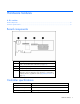
Hardware features In this section Board components ................................................................................................................................... 5 Controller specifications ............................................................................................................................ 5 Board components Item ID Description 1 Runtime LEDs. To interpret the illumination pattern of these LEDs, refer to "Controller board runtime LEDs (on page 30)".
Temperature range Operating, 10°C to 55°C (50°F to 131°F) Storage, -30°C to 60°C (-22°F to 140°F) Relative humidity (noncondensing) Operating, 10% to 90%; storage, 5% to 90% RAID levels supported RAID 0 and 1+0; also RAID 5 if the cache is upgraded ("Upgrading the cache" on page 20) Type of edge connector PCIe x8 (fits in slots that have a physical size of x8 or greater; operates at the speed rating of the slot, up to a maximum of x4) PCIe transfer rate Up to 1.
Overview of the installation procedure In this section Installing the controller in an unconfigured server ......................................................................................... 7 Installing the controller in a previously configured server ............................................................................... 7 Installing the controller in an unconfigured server New HP ProLiant server models self-configure when they are powered up for the first time.
9. Update the Management Agents ("Installing Management Agents" on page 18) if new versions are available. The server is now ready to use. If you want to create additional logical drives, you may now do so.
Installing the controller hardware In this section Before beginning the installation ................................................................................................................ 9 Preparing the server ................................................................................................................................. 9 Installing the controller board ....................................................................................................................
4. Slide the controller board along the slot alignment guide if applicable, and press the board firmly into the slot so that the contacts on the board edge are properly seated in the system board connector. 5. Secure the controller board in place with the retaining screw. If there is a guide latch on the rear of the board, close the latch. 6. Connect storage devices to the controller. (For details of the procedure, see "Connecting storage devices (on page 10).
Updating the firmware In this section Methods for updating the firmware........................................................................................................... 11 Methods for updating the firmware To update the firmware on the server, controller, or hard drives, use Smart Components. These components are available on the Firmware Maintenance CD. A more recent version of a particular server or controller component might be available on the support page of the HP website (http://www.hp.
Configuring an array In this section Introduction ........................................................................................................................................... 12 Comparing the utilities ............................................................................................................................ 12 Using ORCA.......................................................................................................................................... 13 Using ACU .....
Supported features ACU CPQONLIN ORCA Uses a wizard to suggest the optimum configuration for an unconfigured controller + + -- Describes configuration errors + -- -- Supported procedures ACU CPQONLIN ORCA Creation and deletion of arrays and logical drives + + + Assignment of RAID level + + + Sharing of spare drives among several arrays + + -- Assignment of multiple spare drives per array + + -- Setting of stripe size + + -- Migration of RAID level or stripe size + + --
NOTE: You cannot use ORCA to configure one spare drive to be shared among several arrays. Only ACU enables you to configure shared spare drives. 3. Press the Enter key to accept the settings. 4. Press the F8 key to confirm the settings and save the new configuration. After several seconds, the Configuration Saved screen appears. 5. Press the Enter key to continue. You can now create another logical drive by repeating the previous steps.
3. Select the Controller Settings option below Controller Options. The Controller Settings screen appears. Drive rebuild Drive rebuild occurs after a physical drive fails and is replaced. Only logical drives that are configured with RAID 1+0 or RAID 5 can be rebuilt. Priority settings To set the drive rebuild priority: 1. Highlight the controller. 2. Select the controller settings: • If you choose low priority for drive rebuild, drive rebuilding occurs when I/O to the drive is inactive.
Migrating RAID level and stripe size online Using CPQONLIN, you can modify both the RAID level and stripe size of an existing logical drive while online. IMPORTANT: Be sure that the cache battery is connected and fully charged before beginning an array expansion, RAID level migration, or stripe size migration. To migrate a drive: 1. Select the drive setting option under the logical drive menu for the drive you intend to modify. 2.
Setting the boot controller and controller order In this section Setting a controller as the boot controller .................................................................................................. 17 Setting the controller order ...................................................................................................................... 17 Setting a controller as the boot controller The following procedure enables you only to set a controller as the boot controller.
Installing device drivers and Management Agents In this section Installing device drivers........................................................................................................................... 18 Installing Management Agents .................................................................................................................
Upgrading or replacing controller options In this section Replacing a battery ................................................................................................................................ 19 Upgrading the cache .............................................................................................................................. 20 Replacing a battery WARNING: There is a risk of explosion, fire, or personal injury if the battery pack is not properly handled.
4. Lift the battery off the cache board (2). 5. Mount the new battery on the cache board by reversing the procedure used in steps 3 and 4. 6. Reinstall the cache board and its battery on the controller by reversing the procedure used in step 2. IMPORTANT: If the cache is not properly connected, the controller will not boot. NOTE: After installing a battery pack, you might see a POST message during reboot indicating that the array accelerator (cache) is temporarily disabled.
b. Pull the cache module out of the DIMM slot (2). 3. Insert the cache upgrade module and its attached battery into the DIMM slot on the controller. IMPORTANT: If the cache is not properly connected, the controller will not boot.
Replacing, moving, or adding hard drives In this section Identifying the status of a hard drive ......................................................................................................... 22 Recognizing hard drive failure ................................................................................................................. 23 Replacing hard drives .............................................................................................................................
Online/Activity LED (green) Fault/UID LED (amber/blue) Interpretation On Off The drive is online, but it is not active currently. Flashing regularly (1 Hz) Amber, flashing regularly (1 Hz) Do not remove the drive. Removing a drive may terminate the current operation and cause data loss. The drive is part of an array that is undergoing capacity expansion or stripe migration, but a predictive failure alert has been received for this drive.
Effects of a hard drive failure When a hard drive fails, all logical drives that are in the same array are affected. Each logical drive in an array can use a different fault-tolerance method, so each logical drive can be affected differently. • RAID 0 configurations cannot tolerate drive failure. If any physical drive in the array fails, all nonfault-tolerant (RAID 0) logical drives in the same array will also fail.
If you insert a hot-pluggable drive into a drive bay while the system power is on, all disk activity in the array pauses for a second or two while the new drive is spinning up. When the drive has achieved its normal spin rate, data recovery to the replacement drive begins automatically (as indicated by the blinking Online/Activity LED on the replacement drive) if the array is in a fault-tolerant configuration.
Time required for a rebuild The time required for a rebuild varies considerably, depending on several factors: • The priority that the rebuild is given over normal I/O operations (you can change the priority setting by using ACU) • The amount of I/O activity during the rebuild operation • The rotational speed of the hard drives • The availability of drive cache • The brand, model, and age of the drives • The amount of unused capacity on the drives • For RAID 5, the number of drives in the array
2. Restore data from backup. Case 2: The replacement drive has failed. Verify that the replacement drive is of the correct capacity and is a supported model. If these factors are not the cause of the problem, use a different drive as the replacement. Case 3: Another drive in the array has failed. A drive that has recently failed can sometimes be made temporarily operational again by cycling the server power. 1. Power down the server. 2.
Moving drives and arrays You can move drives to other ID positions on the same array controller. You can also move a complete array from one controller to another, even if the controllers are on different servers. Before you move drives, the following conditions must be met: • The server must be powered down. • If moving the drives to a different server, the new server must have enough empty bays to accommodate all the drives simultaneously.
The expansion process is illustrated in the following figure, in which the original array (containing data) is shown with a dashed border and the newly added drives (containing no data) are shown unshaded. The array controller adds the new drives to the array and redistributes the original logical drives over the enlarged array one logical drive at a time. This process liberates some storage capacity on each of the physical drives in the array.
Diagnosing array problems In this section Controller board runtime LEDs.................................................................................................................. 30 Battery pack LEDs................................................................................................................................... 31 Diagnostic tools .....................................................................................................................................
Idle task LED status Gas pedal LED status Controller CPU activity level Blinking Off 0–25% Off Blinking 25–50% Off On steadily 50–75% On steadily On steadily 75–100% Battery pack LEDs Only the cache upgrade module has a battery pack. The LEDs for the battery pack are viewable on the cache board. Item 1 (amber LED) Item 2 (green LED) Interpretation — Steady glow The cache batteries are being charged. (The charging process takes less than three hours.
Item 1 (amber LED) Item 2 (green LED) Interpretation Slow blink (once every 16 seconds) — This display pattern occurs after the system is powered down if the cache contains data that has not yet been written to the drives. Restore system power as soon as possible to prevent data loss. (A fully charged battery pack can preserve cached data for up to three days.) The life expectancy of a battery pack is typically three years or more, depending on the cache module size.
Electrostatic discharge In this section Preventing electrostatic discharge............................................................................................................. 33 Grounding methods to prevent electrostatic discharge ................................................................................ 33 Preventing electrostatic discharge To prevent damaging the system, be aware of the precautions you need to follow when setting up the system or handling parts.
Regulatory compliance notices In this section European Union regulatory notice ............................................................................................................ 34 BSMI notice ........................................................................................................................................... 34 Korean class B notice..............................................................................................................................
Korean class B notice Battery replacement notice This component uses a nickel metal hydride (NiMH) battery pack. WARNING: There is a risk of explosion, fire, or personal injury if a battery pack is mishandled. To reduce this risk: • Do not attempt to recharge the batteries if they are disconnected from the controller. • Do not expose the battery pack to water, or to temperatures higher than 60°C (140°F). • Do not abuse, disassemble, crush, or puncture the battery pack. • Do not short the external contacts.
Acronyms and abbreviations ACR Array Configuration Replicator ACU Array Configuration Utility ADG Advanced Data Guarding (also known as RAID 6) ADU Array Diagnostics Utility BBWC battery-backed write cache CPQONLIN NetWare Online Array Configuration Utility ORCA Option ROM Configuration for Arrays POST Power-On Self Test RBSU ROM-Based Setup Utility SA Smart Array SIM Systems Insight Manager Acronyms and abbreviations 36
Index A ACU (Array Configuration Utility) 14 adding drives 15, 28 ADU (Array Diagnostic Utility) 32 array capacity expansion 28 Array Configuration Utility (ACU) 14 array controller installation overview 7 Array Diagnostic Utility (ADU) 32 array, configuring 12, 15 array, moving 28 automatic data recovery (rebuild) 25 B batteries, replacing 19 battery pack LEDs 31 battery replacement notice 35 board components 5 boot controller, setting 17 BSMI notice 34 C cache, replacing 20 compromised fault tolerance 2
M Management Agents, updating 18 moving an array 28 O Option ROM Configuration for Arrays (ORCA) 13 ORCA (Option ROM Configuration for Arrays) 13 overview of installation process 7 P POST error messages 23, 32 power requirements 5 R rebuild, abnormal termination of 26 rebuild, description of 25 rebuild, time required for 26 regulatory compliance notices 34 replacing hard drives 22 replacing the batteries 19 ROM, updating 11 runtime LEDs 30 S Server Diagnostics utility 32 specifications, controller 5 sta