HP ProLiant SL4545 G7 Server Node User Guide Abstract This document is for the person who installs, administers, and troubleshoots servers and storage systems. HP assumes you are qualified in the servicing of computer equipment and trained in recognizing hazards in products with hazardous energy levels.
© Copyright 2012, 2013 Hewlett-Packard Development Company, L.P. The information contained herein is subject to change without notice. The only warranties for HP products and services are set forth in the express warranty statements accompanying such products and services. Nothing herein should be construed as constituting an additional warranty. HP shall not be liable for technical or editorial errors or omissions contained herein. Microsoft® and Windows® are U.S.
Contents Component identification ............................................................................................................... 6 Node component identification ................................................................................................................... 6 Front panel components ................................................................................................................... 6 Front panel LEDs and buttons ..............................................
Hot-plug hard drive guidelines .................................................................................................................. 38 Removing a drive blank .................................................................................................................. 39 Installing a hot-plug SATA hard drive ............................................................................................... 39 Controller options ..................................................................
Specifications ............................................................................................................................. 60 Environmental specifications ..................................................................................................................... 60 Hot-plug power supply calculations ............................................................................................................ 60 Support and other resources ..........................................
Component identification Node component identification Front panel components Item Description 1 Hard drive bay 1 2 Hard drive bay 2 3 Node release button 4 USB connectors (2) 5 VGA connector Front panel LEDs and buttons Item Description Status 1 UID LED button Blue = Activated Flashing blue = System is being remotely managed or firmware update is in progress.
Item Description Status 2 Node release button — 3 System Health LED Green = Normal Flashing amber = System degraded Flashing red = System critical 4 Power On/Standby button and system power LED Green = System on Amber = System is in Standby mode, but power is still applied. Off = Power is not connected, or power supply has failed.
Item Description 5 Reserved connector 6 SATA 1 connector 7 SATA 2 connector 8 Reserved connector 9 System battery 10 Reserved connector 11 Internal USB connector 12 Reserved connector 13 System maintenance switch (SW1) 14 System maintenance switch (SW4) 15 LED power connector 16 iLO connector 17 NIC 1 connector (bottom) 18 NIC 2 connector (top) 19 USB/VGA connector 20 Personality board connector 21 TPM connector 22 Processor socket 1 23 Processor 2 DIMM slots (6) 24
Position Default Function S1 Off Off—iLO security is enabled. On—iLO security is disabled. S2 Off Off—System configuration can be changed. On—System configuration is locked. S3 Off Reserved S4 Off Reserved S5 Off Off—Power-on password enabled. On—Power-on password disabled. S6 Off Off—No function On—ROM reads system configuration as invalid.
Personality board components Item Description 1 Hard drive power connector 2 RPS connector 3 Serial connector* 4 LED cable connector* 5 Power connector 6 NIC 1 connector 7 NIC 2 connector 8 iLO connector 9 x24 personality board assembly connector *This connector is on the bottom of the personality board. Chassis component identification The following sections provide information on chassis LEDs and connectors.
Front panel components • 1 node chassis Item Description 1 Node drives 2 LFF drive health LED 3 LFF drive UID 4 Drives controlled by the array controller a. Port 1i b.
Item Description 1 Node 1 2 Node drives 3 LFF drive health LED 4 LFF drive UID 5 Drives controlled by node 1 P420i array controller 6 Node 2 7 Drives controlled by node 2 P420i array controller 8 Drive display boards 9 Node VGA connector 10 Node USB connectors 11 Node Power On/Standby button and system power LED 12 Node health LED 13 Node release button 14 Node UID LED button • 3 node chassis Item Description 1 Node 1 2 Node drives 3 LFF drive health LED 4 LFF drive
Item Description 16 Node UID LED button Hard drive display LEDs LED behavior Definition Off • • • Drive is not installed. Drive is not a member of any RAID volumes. Drive is a spare drive that is inactive or has been activated but has not been rebuilt. Notes: • • Solid green Drive is not rebuilding. Drive is not a volume undergoing capacity expansion. All of the following conditions apply: • • • • Drive is a member of a RAID volume. Drive is not an inactive spare drive.
LED behavior Definition Green Storage system health is good. Amber System requires service or a fault is detected. Check hard drives, hard drive backplane, RAID controller, and system fans. UID LEDs LED behavior Definition Off Normal operating mode Blue flashing Hard drive segment is selected; hard drive is in locate mode. Firmware is being flashed.
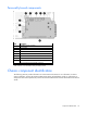
• 2 node chassis Item Description 1 System fans 2 I/O module for node 1 3 Management module 4 Power supplies 5 I/O module for node 2 • 3 node chassis Item Description 1 System fans 2 I/O module for node 1 3 Management module 4 I/O module for node 2 5 Power supplies 6 I/O module for node 3 Component identification 15
I/O module connectors and LEDs • 1 Gb I/O module Item Description 1 Activity LED 2 1Gb connectors 3 I/O module health LED 4 Serial connector 5 Link LED • 10 Gb I/O module Item Description 1 1 Gb connectors 2 I/O module health LED 3 QSFP 10 Gb Ethernet or 40Gb IB connector, depending on configuration 4 SFP+ 10Gb Ethernet connector Component identification 16
Item Description 5 Serial connector 6 Link LED 7 Activity LED 8 Activity LED 9 Link LED Description Status Health LED Off = I/O module is in good health. Amber = I/O module has one of the following health issues: • • • Thermal alarm on a mezzanine card I/O module power has failed on one of the power rails. The I/O module is not fully seated in the connector.
Description Status UID LED Blue = Activated Flashing blue = System is being remotely managed.
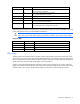
2 node drive bay numbering 3 node drive bay numbering Component identification 19
Power supply LED Power LED Status Off • • • Green AC is present and main 12 V output is enabled. No AC power to power supply units. Check the AC power cord. AC is present. Standby output is on; output is disabled. Power supply failure (includes overvoltage and overtemperature) Fan LED LED color System fan status Off The fan is working or power is off. Solid amber The fan module has failed.
Operations Powering up the system 1. Connect the power cables to the power supplies. 2. Connect the power cables to the power source (UPS or wall outlet) or to an installed PDU. 3. Press the Power On/Standby button on the node. Power down the node Before powering down the node for any upgrade or maintenance procedures, perform a backup of critical server data and programs. IMPORTANT: When the node is in standby mode, auxiliary power is still being provided to the system.
c. Remove the node. CAUTION: To avoid damage to the device, do not use the removal handle to carry it. 3. Place the node on a flat, level surface. Remove the access panel To remove the component: 1. Power down the node (on page 21). 2. Remove the node ("Remove a node from the chassis" on page 21). 3. Press the access panel release button.
4. Slide the access panel toward the rear of the node, and then lift to remove the panel. Install the access panel 1. Place the access panel on top of the node. 2. Slide the access panel forward until it clicks into place. Remove the processor air baffle 1. Power down the node (on page 21). 2. Remove the node from the chassis ("Remove a node from the chassis" on page 21). 3. Remove the access panel (on page 22). 4. Remove the processor air baffle.
Setup Optional installation services Delivered by experienced, certified engineers, HP Care Pack services help you keep your servers up and running with support packages tailored specifically for HP ProLiant systems. HP Care Packs let you integrate both hardware and software support into a single package. A number of service level options are available to meet your needs.
Space and airflow requirements To allow for servicing and adequate airflow, observe the following space and airflow requirements when deciding where to install a rack: • Leave a minimum clearance of 63.5 cm (25 in) in front of the rack. • Leave a minimum clearance of 76.2 cm (30 in) behind the rack. • Leave a minimum clearance of 121.9 cm (48 in) from the back of the rack to the back of another rack or row of racks.
Power requirements Installation of this equipment must comply with local and regional electrical regulations governing the installation of information technology equipment by licensed electricians. This equipment is designed to operate in installations covered by NFPA 70, 1999 Edition (National Electric Code) and NFPA-75, 1992 (code for Protection of Electronic Computer/Data Processing Equipment).
WARNING: To reduce the risk of personal injury or damage to the equipment, be sure that: • • • • • The leveling jacks are extended to the floor. The full weight of the rack rests on the leveling jacks. The stabilizing feet are attached to the rack if it is a single-rack installation. The racks are coupled together in multiple-rack installations. Only one component is extended at a time. A rack may become unstable if more than one component is extended for any reason.
Configuring the chassis For further information on setting up and configuring your system, see the HP ProLiant SL4500 Series Quick Setup Instructions and the HP ProLiant SL4500 Series Setup and Installation Guide. Powering up and configuring the server To power up the server, press the Power On/Standby button. While the server boots, RBSU and the ORCA utility are automatically configured to prepare the server for operating system installation.
Before deploying the management software and creating provisioning policies, do the following: • Complete the installation checklist. • Be sure that the HP ProLiant SL4545 G7 Server, switches, and associated storage resources are configured. • Verify that a supported operating system is installed. If the operating system has not been installed, see the operating system installation documentation.
Hardware options installation Introduction If more than one option is being installed, read the installation instructions for all the hardware options and identify similar steps to streamline the installation process. WARNING: To reduce the risk of personal injury from hot surfaces, allow the drives and the internal system components to cool before touching them. CAUTION: To prevent damage to electrical components, properly ground the server before beginning any installation procedure.
6. Remove the heatsink blank. Retain the heatsink blank for future use. 7. Remove the processor socket protective cover. Save the cover for future use. CAUTION: Failure to completely open the processor locking lever prevents the processor from seating during installation, leading to hardware damage.
8. Open the processor locking lever and the processor socket retaining bracket. IMPORTANT: Be sure the processor remains inside the processor installation tool. 9. If the processor has separated from the installation tool, carefully reinsert the processor into the tool. Handle the processor by the edges only, and do not touch the bottom of the processor, especially the contact area.
10. Align the processor installation tool with the socket and install the processor. THE PINS ON THE SYSTEM BOARD ARE VERY FRAGILE AND EASILY DAMAGED. CAUTION: THE PINS ON THE SYSTEM BOARD ARE VERY FRAGILE AND EASILY DAMAGED. To avoid damage to the system board: • Never install or remove a processor without using the processor installation tool. • Do not touch the processor socket contacts. • Do not tilt or slide the processor when lowering the processor into the socket. 11.
12. Close the processor socket retaining bracket and the processor locking lever. CAUTION: Be sure to close the processor socket retaining bracket before closing the processor locking lever. The lever should close without resistance. Forcing the lever closed can damage the processor and socket, requiring system board replacement. 13. Install the heatsink: NOTE: Make sure the wedge on the heatsink faces away from the DIMMs. a. Remove the protective covering from the heatsink. b.
15. Install the access panel (on page 23). 16. Install the node into the chassis ("Installing a node into the chassis" on page 27). 17. Power up the node ("Powering up the system" on page 21). Memory options The node supports single- and dual-rank PC3L-10600 (DDR-1333) RDIMMs operating at up to 1333 MT/s.
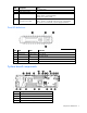
DIMM identification To determine DIMM characteristics, use the label attached to the DIMM and the following illustration and table. Item Description Definition 1 Size — 2 Rank 1R 2R 3R 4R 3 Data width x4 = 4-bit x8 = 8-bit 4 Voltage rating L = Low voltage (1.35V) U = Ultra low voltage (1.
Advanced Memory Protection options are configured in RBSU. If the requested AMP mode is not supported by the installed DIMM configuration, the node boots in Advanced ECC mode. For more information, see "HP ROM-Based Setup Utility (on page 48)." Maximum capacity DIMM type DIMM rank One processor Two processors RDIMM Single-rank 24 GB 48 GB RDIMM Dual-rank 96 GB 192 GB For the latest memory configuration information, see the QuickSpecs on the HP website (http://www.hp.com).
Population order For memory configurations with a single processor or multiple processors, populate the DIMM slots sequentially in alphabetical order (A through F). After installing the DIMMs, use RBSU to configure Advanced ECC, online spare, or lockstep memory support. Installing a DIMM CAUTION: To avoid damage to the hard drives, memory, and other system components, the air baffle, drive blanks, and access panel must be installed when the server is powered up. 1. Power down the node (on page 21). 2.
Removing a drive blank Remove the component as indicated. CAUTION: To prevent improper cooling and thermal damage, do not operate the server unless all bays are populated with either a component or a blank. Installing a hot-plug SATA hard drive 1. Remove the drive blank ("Removing a drive blank" on page 39). 2. Prepare the drive.
3. Install the hard drive. 4. Determine the status of the drive from the drive LED definitions (on page 7). Controller options The chassis I/O module ships standard with an HP Smart Array P420i controller. • For more information about product features, specifications, options, configurations, and compatibility, see the product QuickSpecs on the HP Product Bulletin website (http://www.hp.com/go/productbulletin).
CAUTION: Always observe the guidelines in this document. Failure to follow these guidelines can cause hardware damage or halt data access. When installing or replacing a TPM, observe the following guidelines: • Do not remove an installed TPM. Once installed, the TPM becomes a permanent part of the system board. • When installing or replacing hardware, HP service providers cannot enable the TPM or the encryption technology. For security reasons, only the customer can enable these features.
5. Install the TPM board. Press down on the connector to seat the board ("System board components" on page 7). 6. Install the TPM security rivet by pressing the rivet firmly into the system board. 7. Install the access panel (on page 23). 8. Install the node into the chassis ("Installing a node into the chassis" on page 27). 9. Power up the node ("Powering up the system" on page 21).
• Always store copies of the recovery key/password away from the node. • Do not save the recovery key/password on the encrypted hard drive. Enabling the Trusted Platform Module 1. When prompted during the start-up sequence, access RBSU by pressing the F9 key. 2. From the Main Menu, select Server Security. 3. From the Server Security Menu, select Trusted Platform Module. 4. From the Trusted Platform Module Menu, select TPM Functionality. 5.
Cabling Personality board cabling SATA cabling Internal power cabling The power cable routes over the HDD LED cable and SATA cables. Connect and route the cables in the following order: 1. HDD data LED cable (bottom) 2.
3. Power cable RPS cabling The RPS cable routes with the front LED cable under the SFF backplane power cable and the USB/VGA cable. Connect and route the cables in the following order: 1. RPS cable and front LED cable (bottom) 2. SFF backplane power cable 3. USB/VGA cable Front LED cabling WARNING: Only authorized technicians trained by HP should attempt to replace this component.
SFF backplane power cabling The SFF backplane power cable routes on top of the RPS cable and front LED cable, and under the USB/VGA cable. Secure the SFF backplane power cable in the plastic clip provided. Connect and route the cables in the following order: 1. RPS cable and front LED cable (bottom) 2. SFF backplane power cable, secured in the plastic clip 3. USB/VGA cable USB/VGA cabling The USB/VGA cable routes on top of the SFF backplane power cable, RPS cable, and front LED cable.
Software and configuration utilities Configuration tools HP Service Pack for ProLiant SPP is a release set that contains a comprehensive collection of firmware and system software components, all tested together as a single solution stack for HP ProLiant servers, their options, BladeSystem enclosures, and limited HP external storage. SPP has several key features for updating HP ProLiant servers.
For more information about HP SUM and to access the HP Smart Update Manager User Guide, see the HP website (http://www.hp.com/go/hpsum/documentation).
NOTE: If the boot drive is not empty or has been written to in the past, ORCA does not automatically configure the array. You must run ORCA to configure the array settings. Drives installed Drives used RAID level 1 1 RAID 0 2 2 RAID 1 3, 4, 5, or 6 3, 4, 5, or 6 RAID 5 More than 6 0 None To change any ORCA default settings and override the auto-configuration process, press the F8 key when prompted.
uncorrectable memory error occurs, the system automatically retrieves the good data from the mirrored copy. The system continues to operate normally without any user intervention. If the system supports hot-plug memory, the failed memory can be replaced while the system continues to operate. • RAID Memory Mode—Provides protection levels similar to Mirrored Memory Mode, and it requires less memory allocation than full redundancy.
For more information regarding the default configurations that ORCA uses, see the HP ROM-Based Setup Utility User Guide on the Documentation CD. For more information about the controller and its features, see the HP Smart Array Controllers for HP ProLiant Servers User Guide on the HP website (http://www.hp.com/support/SAC_UG_ProLiantServers_en). To configure arrays, see the Configuring Arrays on HP Smart Array Controllers Reference Guide on the HP website (http://www.hp.com/support/CASAC_RG_en).
ROMPaq utility The ROMPaq utility enables you to upgrade the system firmware (BIOS). To upgrade the firmware, insert a ROMPaq USB Key into an available USB port and boot the system. In addition to ROMPaq, Online Flash Components for Windows and Linux operating systems are available for updating the system firmware. The ROMPaq utility checks the system and provides a choice (if more than one exists) of available firmware revisions. For more information, go to the HP website (http://www.hp.
Safety and security benefits When you flash the system ROM, ROMPaq writes over the backup ROM and saves the current ROM as a backup, enabling you to switch easily to the alternate ROM version if the new ROM becomes corrupted for any reason. This feature protects the existing ROM version, even if you experience a power failure while flashing the ROM. USB support HP provides both standard USB 2.0 support and legacy USB 2.0 support.
NOTE: The current version of SmartStart provides the memory spare part numbers for the node. To download the latest version, see the HP website (http://www.hp.com/support). Integrated Management Log The IML records hundreds of events and stores them in an easy-to-view form. The IML timestamps each event with 1-minute granularity.
Keeping the system current Drivers IMPORTANT: Always perform a backup before installing or updating device drivers. The node includes new hardware that may not have driver support on all OS installation media. Drivers, ROM images, and value-add software can be downloaded as part of an SPP ("HP Service Pack for ProLiant" on page 47). If you are installing drivers from SPP, be sure that you are using the latest SPP version that your node supports.
Care Pack HP Care Pack Services offer upgraded service levels to extend and expand bundled services with easy-to-buy, easy-to-use support packages that help you make the most of your server investments. For more information, see the HP website (http://www.hp.com/services/carepack).
System battery If the node no longer automatically displays the correct date and time, you might have to replace the battery that provides power to the real-time clock. Under normal use, battery life is 5 to 10 years. WARNING: The computer contains an internal lithium manganese dioxide, a vanadium pentoxide, or an alkaline battery pack. A risk of fire and burns exists if the battery pack is not properly handled. To reduce the risk of personal injury: • • • • Do not attempt to recharge the battery.
Regulatory information Safety and regulatory compliance For safety, environmental, and regulatory information, see Safety and Compliance Information for Server, Storage, Power, Networking, and Rack Products, available at the HP website (http://www.hp.com/support/Safety-Compliance-EnterpriseProducts). Turkey RoHS material content declaration Ukraine RoHS material content declaration Warranty information HP ProLiant and X86 Servers and Options (http://www.hp.
Electrostatic discharge Preventing electrostatic discharge To prevent damaging the system, be aware of the precautions you need to follow when setting up the system or handling parts. A discharge of static electricity from a finger or other conductor may damage system boards or other static-sensitive devices. This type of damage may reduce the life expectancy of the device. To prevent electrostatic damage: • Avoid hand contact by transporting and storing products in static-safe containers.
Specifications Environmental specifications Specification Value Temperature range* Operating 10°C to 35°C (50°F to 95°F) Shipping -40°C to 70°C (-40°F to 158°F) Maximum wet bulb temperature 28°C (82.4°F) Relative humidity (noncondensing)** Operating 10% to 90% Nonoperating 5% to 95% * All temperature ratings shown are for sea level. An altitude derating of 1°C per 300 m (1.8°F per 1,000 ft) to 3,048 m (10,000 ft) is applicable. No direct sunlight allowed.
Support and other resources Before you contact HP Be sure to have the following information available before you call HP: • Active Health System log (HP ProLiant Gen8 or later products) Download and have available an Active Health System log for 3 days before the failure was detected. For more information, see the HP iLO 4 User Guide or HP Intelligent Provisioning User Guide on the HP website (http://www.hp.com/go/ilo/docs).
providers or service partners) identifies that the repair can be accomplished by the use of a CSR part, HP will ship that part directly to you for replacement. There are two categories of CSR parts: • Mandatory—Parts for which customer self repair is mandatory. If you request HP to replace these parts, you will be charged for the travel and labor costs of this service. • Optional—Parts for which customer self repair is optional. These parts are also designed for customer self repair.
Pour plus d'informations sur le programme CSR de HP, contactez votre Mainteneur Agrée local. Pour plus d'informations sur ce programme en Amérique du Nord, consultez le site Web HP (http://www.hp.com/go/selfrepair). Riparazione da parte del cliente Per abbreviare i tempi di riparazione e garantire una maggiore flessibilità nella sostituzione di parti difettose, i prodotti HP sono realizzati con numerosi componenti che possono essere riparati direttamente dal cliente (CSR, Customer Self Repair).
HINWEIS: Einige Teile sind nicht für Customer Self Repair ausgelegt. Um den Garantieanspruch des Kunden zu erfüllen, muss das Teil von einem HP Servicepartner ersetzt werden. Im illustrierten Teilekatalog sind diese Teile mit „No“ bzw. „Nein“ gekennzeichnet. CSR-Teile werden abhängig von der Verfügbarkeit und vom Lieferziel am folgenden Geschäftstag geliefert. Für bestimmte Standorte ist eine Lieferung am selben Tag oder innerhalb von vier Stunden gegen einen Aufpreis verfügbar.
sustituciones que lleve a cabo el cliente, HP se hará cargo de todos los gastos de envío y devolución de componentes y escogerá la empresa de transporte que se utilice para dicho servicio. Para obtener más información acerca del programa de Reparaciones del propio cliente de HP, póngase en contacto con su proveedor de servicios local. Si está interesado en el programa para Norteamérica, visite la página web de HP siguiente (http://www.hp.com/go/selfrepair).
Opcional – Peças cujo reparo feito pelo cliente é opcional. Essas peças também são projetadas para o reparo feito pelo cliente. No entanto, se desejar que a HP as substitua, pode haver ou não a cobrança de taxa adicional, dependendo do tipo de serviço de garantia destinado ao produto. OBSERVAÇÃO: Algumas peças da HP não são projetadas para o reparo feito pelo cliente. A fim de cumprir a garantia do cliente, a HP exige que um técnico autorizado substitua a peça.
Support and other resources 67
Support and other resources 68
Appendix: Install the hpahcisr driver for OS installation Installing a Windows or Linux OS To take advantage of SATA RAID functionality on the node, you must install the hpahcisr driver. To obtain the driver and install it with the operating system, complete the following steps: 1. Enable SATA RAID functionality in RBSU ("Enabling SATA RAID functionality in RBSU" on page 69). 2. Create a drivers diskette for the OS to be installed on the node: 3.
Installing a Windows OS 1. Create a logical volume for the driver using ORCA. 2. Mount the Windows OS to a drive or by using iLO. 3. Connect the USB device containing the drivers to the USB connectors on the node. 4. Boot the OS from the ISO. 5. Once the OS boots, the Install Windows screen is displayed. 6. Select the appropriate entry using the drop down box for each of the following: o Language o Time and currency format o Keyboard or input method 7. Click Next. 8.
6. Connect the selected device to the server and press Enter to begin. For example, if you selected USB drive, insert the USB drive into the USB connector on the server. The USB drive is cleared of information and the device driver diskette is created. 7. 8. When completed, the following message is displayed: The copies are identical Press to continue... The following message is displayed: Do you wish to view the Release Notes for this DRIVER UPDATE DISKETTE? 9.
Acronyms and abbreviations ABEND abnormal end ACU Array Configuration Utility ASR Automatic Server Recovery CSA Canadian Standards Association CSR Customer Self Repair DDR double data rate HP SIM HP Systems Insight Manager IEC International Electrotechnical Commission iLO Integrated Lights-Out IML Integrated Management Log NMI nonmaskable interrupt NVRAM nonvolatile memory Acronyms and abbreviations 72
ORCA Option ROM Configuration for Arrays POST Power-On Self Test QSFP quad small form-factor pluggable RBSU ROM-Based Setup Utility RDIMM registered dual in-line memory module SAS serial attached SCSI SATA serial ATA SFF small form factor SFP small form-factor pluggable SFP+ small form-factor pluggable - plus SIM Systems Insight Manager TMRA recommended ambient operating temperature UID unit identification UPS uninterruptible power system Acronyms and abbreviations 73
USB universal serial bus VCA Version Control Agent Acronyms and abbreviations 74
Documentation feedback HP is committed to providing documentation that meets your needs. To help us improve the documentation, send any errors, suggestions, or comments to Documentation Feedback (mailto:docsfeedback@hp.com). Include the document title and part number, version number, or the URL when submitting your feedback.
Index A access panel 22, 23 ACU (Array Configuration Utility) Advanced ECC memory 37, 49 air baffle 23 airflow requirements 25 Appendix 69 Array Configuration Utility (ACU) ASR (Automatic Server Recovery) authorized reseller 61 auto-configuration process 48 Automatic Server Recovery (ASR) 50 50 51 51 B batteries, replacing 57 battery 57 BIOS Serial Console 49 BIOS upgrade 52 boot options 49 buttons 6 buttons, front panel 6 C cables 44 cabling 44, 45, 46 cabling, front LED 45 cabling, internal power 44
front panel components 6, 11 G grounding methods 59 grounding requirements 26 H hard drive blanks 39 hard drive LEDs 7, 13 hard drive power connector 10 hard drives, determining status of 7 hardware options 27, 30 hardware options installation 30 health driver 51 health LEDs 11 HP contact information 61 HP Insight Diagnostics 53 HP Insight Remote Support software 54 HP Service Pack for ProLiant 47 HP Smart Update Manager overview 47 hpahcisr 69, 70, 71 I I/O module connectors 16 I/O module LEDs 16 iLO (I
power supply LEDs 20 powering down 21 powering up 21, 28 preparation procedures 21 pro-active notification 55 processor 30 Product ID 51 R rack installation 24, 26, 27 rack resources 24 rack warnings 26 RBSU (ROM-Based Setup Utility) 48, 49 RBSU configuration 48 rear panel components 14 redundant ROM 52 registering the server 29 regulatory compliance notices 58 release button 6 remote support and analysis tools 54 removing the access panel 22 requirements, airflow 25 requirements, power 26, 60 requirements