HP ProLiant SL335s G7 Server User Guide Abstract This document is for the person who installs, administers, and troubleshoots servers and storage systems. HP assumes you are qualified in the servicing of computer equipment and trained in recognizing hazards in products with hazardous energy levels.
© Copyright 2011, 2013 Hewlett-Packard Development Company, L.P. The information contained herein is subject to change without notice. The only warranties for HP products and services are set forth in the express warranty statements accompanying such products and services. Nothing herein should be construed as constituting an additional warranty. HP shall not be liable for technical or editorial errors or omissions contained herein. Microsoft® and Windows® are U.S.
Contents Component identification ............................................................................................................... 6 Front panel components ............................................................................................................................. 6 Front panel LEDs and buttons ...................................................................................................................... 6 Rear panel components .........................................
HP Trusted Platform Module option ............................................................................................................ 33 Installing the Trusted Platform Module board ..................................................................................... 33 Retaining the recovery key/password .............................................................................................. 35 Enabling the Trusted Platform Module..............................................................
Server power-on problems flowchart ................................................................................................ 54 POST problems flowchart ............................................................................................................... 57 OS boot problems flowchart ........................................................................................................... 59 Server fault indications flowchart .................................................................
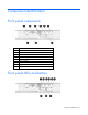
Component identification Front panel components Item Description 1 Serial port 2 VGA port 3 USB 2.
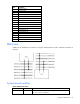
Item Description Status 1 iLO 3 network activity LED Flashing green—Network data activity exists. Off—No network data activity exists, or no network connection exists. 2 iLO 3 network speed LED Green—LAN connection using a 10/100/1000 Mbps link Off—No LAN connection exists. 3 NIC 1 activity LED Flashing green—Network data activity exists. Off—No network data activity exists, or no network connection exists.
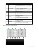
5 Fan 3 6 Fan 1 7 Fan 2 8 Power supply 1 9 Power supply 2 10 Power supply 3 11 Power supply 4 12 Fan 5 13 Fan 6 Rear panel LEDs and buttons Item Description Status 1 Fan 8 power LED Off—Normal Amber—Fan has failed. 2 Fan 7 power LED Off—Normal Amber—Fan has failed. 3 UID LED button Blue—Activated Flashing blue—System is being remotely managed. Off—Deactivated 4 Fan 4 power LED Off—Normal Amber—Fan has failed. 5 Fan 3 power LED Off—Normal Amber—Fan has failed.
Item Description Status 10 Power supply 3 power LED Green—Normal Off—No AC power Amber—Power supply has failed. 11 Power supply 4 power LED Green—Normal Off—No AC power Amber—Power supply has failed. 12 Fan 5 power LED Off—Normal Amber—Fan has failed. 13 Fan 6 power LED Off—Normal Amber—Fan has failed. Amber—Power supply has failed.
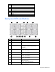
Item Description 15 SATA connector 3 16 Diagnostic LEDs 17 System maintenance switch 18 SATA connector 2 19 SATA connector 1 20 Riser connector 21 TPM module 22 CPU 1 socket 23 CPU1 VRD and CPU2 DIMM VRD 24 CPU 2 socket 25 CPU2 DIMM slot 1A 26 CPU2 DIMM slot 2E 27 CPU2 DIMM slot 3C 28 CPU2 DIMM slot 4B 29 CPU2 DIMM slot 5F 30 CPU2 DIMM slot 6D 31 CPU 2 VRD DIMM slots DIMM slots are identified by the numbers 1 through 6.
Position Default Function S2 Off Off—System configuration can be changed. On—System configuration is locked. S3 Off Reserved S4 Off Reserved S5 Off Off—Power-on password enabled. On—Power-on password disabled. S6 Off Off—No function On—ROM reads system configuration as invalid. When the system maintenance switch position 6 is set to the On position, the system is prepared to erase all system configuration settings from both CMOS and NVRAM.
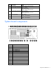
Hard drive numbering The following figure illustrates the location of drives in the server. Item Description 1 SAS/SATA drive 1 2 SAS/SATA drive 2 3 SAS/SATA drive 3 4 SAS/SATA drive 4 NOTE: LFF hard drives are illustrated in the figures in this guide. SFF hard drives are also supported.
Item Color Description 1 Green System Power LED. This LED is on when the system is powered up and 12 V system power is available. This power supply is used to maintain the battery charge and provide supplementary power to the cache microcontroller. 2 Green Auxiliary Power LED. This LED is on when 3.3V auxiliary voltage is detected. The auxiliary voltage is used to preserve BBWC data and is available any time that the system power cords are connected to a power supply. 3 Amber Battery Health LED.
System fans The server has eight system fans located on the rear panel of the chassis. The following figure identifies the system fans by device number. CAUTION: To prevent damage to the server, do not install a combination of redundant and non-redundant fans.
Operations Power down the server WARNING: To reduce the risk of personal injury, electric shock, or damage to the equipment, remove the power cord to remove power from the server. The front panel Power On/Standby button does not completely shut off system power. Portions of the power supply and some internal circuitry remain active until AC power is removed. IMPORTANT: If installing a hot-plug device, it is not necessary to power down the server. 1. Back up the server data. 2.
5. Remove the server from the chassis. 6. Repeat the previous steps to remove the right server from the chassis.
Setup Optional installation services Delivered by experienced, certified engineers, HP Care Pack services help you keep your servers up and running with support packages tailored specifically for HP ProLiant systems. HP Care Packs let you integrate both hardware and software support into a single package. A number of service level options are available to meet your needs.
Space and airflow requirements To allow for servicing and adequate airflow, observe the following space and airflow requirements when deciding where to install a rack: • Leave a minimum clearance of 63.5 cm (25 in) in front of the rack. • Leave a minimum clearance of 76.2 cm (30 in) behind the rack. • Leave a minimum clearance of 121.9 cm (48 in) from the back of the rack to the back of another rack or row of racks.
CAUTION: To reduce the risk of damage to the equipment when installing third-party options: • Do not permit optional equipment to impede airflow around the server or to increase the internal rack temperature beyond the maximum allowable limits. • Do not exceed the manufacturer’s TMRA. Power requirements Installation of this equipment must comply with local and regional electrical regulations governing the installation of information technology equipment by licensed electricians.
Rack warnings WARNING: To reduce the risk of personal injury or damage to the equipment, be sure that: • • • • • The leveling jacks are extended to the floor. The full weight of the rack rests on the leveling jacks. The stabilizing feet are attached to the rack if it is a single-rack installation. The racks are coupled together in multiple-rack installations. Only one component is extended at a time. A rack may become unstable if more than one component is extended for any reason.
2. Rotate the tray handle to lock the power connector. 3. Repeat the previous steps to install the right server into the chassis. 4. Connect peripheral devices to the server. Item Description 1 Serial port 2 VGA port 3 USB 2.
WARNING: To reduce the risk of electric shock or damage to the equipment: • Do not disable the power cord grounding plug. The grounding plug is an important safety feature. • Plug the power cord into a grounded (earthed) electrical outlet that is easily accessible at all times. • Unplug the power cord from the power supply to disconnect power to the equipment. • Do not route the power cord where it can be walked on or pinched by items placed against it.
Hardware options installation Introduction If more than one option is being installed, read the installation instructions for all the hardware options and identify similar steps to streamline the installation process. WARNING: To reduce the risk of personal injury from hot surfaces, allow the drives and the internal system components to cool before touching them. CAUTION: To prevent damage to electrical components, properly ground the server before beginning any installation procedure.
7. Rotate the drive carrier handle down. 8. Lock the drive carrier latches. 9. Install the server into the chassis ("Installing the server into the chassis" on page 20). 10. Power up the server (on page 22). Removing a drive CAUTION: For proper cooling, do not operate the server without the access panel, baffles, expansion slot covers, or blanks installed. If the server supports hot-plug components, minimize the amount of time the access panel is open. To remove the component: 1.
9. Lock the drive carrier latches. 10. Install the server into the chassis ("Installing the server into the chassis" on page 20). 11. Power up the server (on page 22). Processor options The server, with up to eight nodes, supports 16–processor operation. When two processors are installed in a single node, the node supports boot functions through the processor installed in the processor socket 1.
4. Open the processor retaining latch and the processor socket retaining bracket. IMPORTANT: Be sure the processor remains inside the processor installation tool. 5. If the processor has separated from the installation tool, carefully reinsert the processor into the tool.
6. Align the processor installation tool with the socket and install the processor. 7. Press down firmly until the processor installation tool clicks and separates from the processor, and then remove the processor installation tool.
8. Close the processor socket retaining bracket and the processor retaining latch. 9. Remove the heatsink protective cover. CAUTION: Heatsink screws should be tightened and loosened in alternating sequence. Do not overtighten the screws as this can damage the system board, connectors, or screws. When using a torque wrench, tighten the screws to .68 Nm --.90 Nm (6-8 in-lb.) of torque. NOTE: Make sure the wedge on the heatsink faces away from the DIMMs. 10. Install the heatsink: a.
c. Completely tighten the first screw. 11. Install the server into the chassis ("Installing the server into the chassis" on page 20). 12. Power up the server (on page 22). DIMMs Memory configurations The server has 12 DIMM slots that support up to 192 GB maximum system memory. If you add or replace memory modules, follow these guidelines: • You can install DDR3 RDIMM or UDIMM slots (six DIMMs per CPU) with a maximum of 12 (SR or DR) RDIMM, four (QR) RDIMM, or eight (SR/DR) UDIMM slots.
• Install DIMMs in decreasing capacity with the largest DIMMs installed in the banks farthest away from each processor. • Use only HP DIMM part numbers listed in the server QuickSpecs. The server memory protection mode is Advanced ECC memory. In Advanced ECC, the server does not fail because of correctable memory errors. The server provides notification if the level of correctable errors exceeds a predefined threshold rate.
DIMM slots DIMM slots are identified by the numbers 1 through 6. DIMM population order is specified by the letters A through F. Installing a DIMM CAUTION: For proper cooling, do not operate the server without the access panel, baffles, expansion slot covers, or blanks installed. If the server supports hot-plug components, minimize the amount of time the access panel is open. To install the component: 1. Power down the server (on page 15). 2. Disconnect all peripheral cables from the server. 3.
5. Install the DIMM. 6. Install the server into the chassis ("Installing the server into the chassis" on page 20). 7. Power up the server (on page 22). Expansion board options The server supports PCI Express expansion boards. Installing a low-profile expansion board 1. Power down the server (on page 15). 2. Disconnect all peripheral cables from the server. 3. Remove the server from the chassis ("Removing the server from the chassis" on page 15). 4. Install a low-profile expansion board.
5. Connect any required internal or external cables to the expansion board. See the documentation that ships with the expansion board for more information. 6. Install the server into the chassis ("Installing the server into the chassis" on page 20). 7. Power up the server (on page 22). HP Trusted Platform Module option For more information about product features, specifications, options, configurations, and compatibility, see the product QuickSpecs on the HP Product Bulletin website (http://www.hp.
3. Place the server on a flat, level work surface. 4. Remove the access panel. CAUTION: Any attempt to remove an installed TPM from the system board breaks or disfigures the TPM security rivet. Upon locating a broken or disfigured rivet on an installed TPM, administrators should consider the system compromised and take appropriate measures to ensure the integrity of the system data. 5. Install the TPM board. Press down on the connector to seat the board. 6.
Retaining the recovery key/password The recovery key/password is generated during BitLocker™ setup, and can be saved and printed after BitLocker™ is enabled. When using BitLocker™, always retain the recovery key/password. The recovery key/password is required to enter Recovery Mode after BitLocker™ detects a possible compromise of system integrity.
Configuration and utilities Configuration tools SmartStart software SmartStart is a collection of software that optimizes single-server setup, providing a simple and consistent way to deploy server configuration. SmartStart has been tested on many ProLiant server products, resulting in proven, reliable configurations.
refer to the SmartStart Scripting Toolkit User Guide on the HP website (http://h18004.www1.hp.com/products/servers/management/toolkit/documentation.html).
NOTE: If the boot drive is not empty or has been written to in the past, ORCA does not automatically configure the array. You must run ORCA to configure the array settings. Drives installed Drives used RAID level 1 1 RAID 0 2 2 RAID 1 3, 4, 5, or 6 3, 4, 5, or 6 RAID 5 More than 6 0 None To change any ORCA default settings and override the auto-configuration process, press the F8 key when prompted. By default, the auto-configuration process configures the system for the English language.
• Remains available any time that the server is on • Displays on-screen tips for individual steps of a configuration procedure • Beginning with ACU version 8.28.13.0, provides diagnostic functionality on the Diagnostics tab (formerly known as Array Diagnostics Utility). For optimum performance, the minimum display settings are 1024 × 768 resolution and 16-bit color. Servers running Microsoft® operating systems require one of the following supported browsers: • Internet Explorer 6.
Solution while providing optimization for deployment of HP ProLiant servers using HP ProLiant Integration Module. HP Insight Control facilitates the installation, configuration, and deployment of high-volumes of servers through an intuitive, comprehensive console, using either scripting or imaging technology. It makes deploying a server as easy as selecting one, a few, or hundreds of target servers, selecting predefined images or scripts, and clicking Run.
The ROMPaq utility checks the system and provides a choice (if more than one exists) of available firmware revisions. For more information, go to the HP website (http://www.hp.com/go/hpsc) and click on Drivers, Software & Firmware. Then, enter your product name in the Find an HP product field and click Go. Integrated Lights-Out 3 technology The iLO 3 subsystem is a standard component of selected ProLiant servers that provides server health and remote server manageability.
HP Systems Insight Manager HP SIM is a web-based application that allows system administrators to accomplish normal administrative tasks from any remote location, using a web browser. HP SIM provides device management capabilities that consolidate and integrate management data from HP and third-party devices. IMPORTANT: You must install and use HP SIM to benefit from the Pre-Failure Warranty for processors, SAS and SATA drives, and memory modules.
Safety and security benefits When you flash the system ROM, ROMPaq writes over the backup ROM and saves the current ROM as a backup, enabling you to switch easily to the alternate ROM version if the new ROM becomes corrupted for any reason. This feature protects the existing ROM version, even if you experience a power failure while flashing the ROM. USB support and functionality USB support HP provides both standard USB 2.0 support and legacy USB 2.0 support.
HP Insight Diagnostics Online Edition is a web-based application that captures system configuration and other related data needed for effective server management. Available in Microsoft® Windows® and Linux versions, the utility helps to ensure proper system operation. For more information or to download the utility, refer to the HP website (http://www.hp.com/servers/diags).
Remote support and analysis tools HP Insight Remote Support software HP strongly recommends that you install HP Insight Remote Support software to complete the installation or upgrade of your product and to enable enhanced delivery of your HP Warranty, HP Care Pack Service, or HP contractual support agreement.
ProLiant Support Packs PSPs represent operating system-specific bundles of ProLiant optimized drivers, utilities, and management agents. Refer to the PSP website (http://h18000.www1.hp.com/products/servers/management/psp.html). Operating system version support Refer to the operating system support matrix (http://www.hp.com/go/supportos).
Troubleshooting Troubleshooting resources The HP ProLiant Servers Troubleshooting Guide provides procedures for resolving common problems and comprehensive courses of action for fault isolation and identification, error message interpretation, issue resolution, and software maintenance on ProLiant servers and server blades. This guide includes problem-specific flowcharts to help you navigate complex troubleshooting processes. To view the guide, select a language: • English (http://www.hp.
Symbols on equipment The following symbols may be placed on equipment to indicate the presence of potentially hazardous conditions. This symbol indicates the presence of hazardous energy circuits or electric shock hazards. Refer all servicing to qualified personnel. WARNING: To reduce the risk of injury from electric shock hazards, do not open this enclosure. Refer all maintenance, upgrades, and servicing to qualified personnel. This symbol indicates the presence of electric shock hazards.
WARNING: To reduce the risk of electric shock or damage to the equipment: • Do not disable the power cord grounding plug. The grounding plug is an important safety feature. • Plug the power cord into a grounded (earthed) electrical outlet that is easily accessible at all times. • Unplug the power cord from the power supply to disconnect power to the equipment. • Do not route the power cord where it can be walked on or pinched by items placed against it.
2. Record any error messages displayed by the system. 3. Remove all diskettes, CD-ROMs, DVD-ROMs, and USB drive keys. 4. Power down the server and peripheral devices if you will be diagnosing the server offline. If possible, always perform an orderly shutdown: a. Exit any applications. b. Exit the operating system. c. Power down the server (on page 15). 5. Disconnect any peripheral devices not required for testing (any devices not necessary to power up the server).
Service notifications To view the latest service notifications, refer to the HP website (http://www.hp.com/go/bizsupport). Select the appropriate server model, and then click the Troubleshoot a Problem link on the product page. Troubleshooting flowcharts To effectively troubleshoot a problem, HP recommends that you start with the first flowchart in this section, "Start diagnosis flowchart (on page 51)," and follow the appropriate diagnostic path.
General diagnosis flowchart The General diagnosis flowchart provides a generic approach to troubleshooting. If you are unsure of the problem, or if the other flowcharts do not fix the problem, use the following flowchart. Item See 1 "Symptom information (on page 49)" 2 "Loose connections (on page 50)" 3 "Service notifications (on page 51)" 4 The most recent version of a particular server or option firmware is available on the HP Support website (http://www.hp.com/support).
Item See 5 "General memory problems are occurring" in the HP ProLiant Servers Troubleshooting Guide located on the Documentation CD or see "Troubleshooting resources (on page 47)" 6 Server maintenance and service guide, located on the Documentation CD or the HP website (http://www.hp.
Server power-on problems flowchart Symptoms: • The server does not power on. • The system power LED is off or amber.
• The external health LED is red or amber. • The internal health LED is red or amber. NOTE: For the location of server LEDs and information on their statuses, refer to the server documentation.
Troubleshooting 56
POST problems flowchart Symptoms: • Server does not complete POST NOTE: The server has completed POST when the system attempts to access the boot device.
Item See 13 • • "Server information you need" in the HP ProLiant Servers Troubleshooting Guide located on the Documentation CD or see "Troubleshooting resources (on page 47)" "Operating system information you need" in the HP ProLiant Servers Troubleshooting Guide located on the Documentation CD or see "Troubleshooting resources (on page 47)" Troubleshooting 58
OS boot problems flowchart Symptoms: • Server does not boot a previously installed operating system • Server does not boot SmartStart Possible causes: • Corrupted operating system • Hard drive subsystem problem • Incorrect boot order setting in RBSU Item See 1 HP ROM-Based Setup Utility User Guide (http://www.hp.
Server fault indications flowchart Symptoms: • Server boots, but a fault event is reported by Insight Management Agents (on page 42) • Server boots, but the internal health LED, external health LED, or component health LED is red or amber NOTE: For the location of server LEDs and information on their statuses, refer to the server documentation.
Possible causes: • Improperly seated or faulty internal or external component • Unsupported component installed • Redundancy failure • System overtemperature condition Item See 1 • • "Integrated Management Log (on page 44)" or in the HP ProLiant Servers Troubleshooting Guide located on the Documentation CD or see "Troubleshooting resources (on page 47)" "Event list error messages" in the HP ProLiant Servers Troubleshooting Guide located on the Documentation CD or see "Troubleshooting resources
POST error messages and beep codes For a complete listing of error messages, refer to the "POST error messages" in the HP ProLiant Servers Troubleshooting Guide located on the Documentation CD or on the HP website (http://www.hp.com/support).
WARNING: To avoid potential problems, ALWAYS read the warnings and cautionary information in the server documentation before removing, replacing, reseating, or modifying system components.
System battery If the server no longer automatically displays the correct date and time, you might have to replace the battery that provides power to the real-time clock. Under normal use, battery life is 5 to 10 years. WARNING: The computer contains an internal lithium manganese dioxide, a vanadium pentoxide, or an alkaline battery pack. A risk of fire and burns exists if the battery pack is not properly handled. To reduce the risk of personal injury: • • • • Do not attempt to recharge the battery.
Regulatory information Safety and regulatory compliance For safety, environmental, and regulatory information, see Safety and Compliance Information for Server, Storage, Power, Networking, and Rack Products, available at the HP website (http://www.hp.com/support/Safety-Compliance-EnterpriseProducts). Turkey RoHS material content declaration Ukraine RoHS material content declaration Warranty information HP ProLiant and X86 Servers and Options (http://www.hp.
Electrostatic discharge Preventing electrostatic discharge To prevent damaging the system, be aware of the precautions you need to follow when setting up the system or handling parts. A discharge of static electricity from a finger or other conductor may damage system boards or other static-sensitive devices. This type of damage may reduce the life expectancy of the device. To prevent electrostatic damage: • Avoid hand contact by transporting and storing products in static-safe containers.
Specifications Environmental specifications Specification Value Temperature range* Operating 10°C to 35°C (50°F to 95°F) Shipping -30°C to 50°C (-22°F to 122°F) Storage -30°C to 60°C (-22°F to 140°F) Maximum wet bulb temperature 28°C (82.4°F) Relative humidity (noncondensing)** Operating 10% to 90% Non-operating 5% to 95% * All temperature ratings shown are for sea level. An altitude derating of 1°C per 300 m (1.8°F per 1,000 ft) to 3048 m (10,000 ft) is applicable. No direct sunlight allowed.
Support and other resources Before you contact HP Be sure to have the following information available before you call HP: • Active Health System log (HP ProLiant Gen8 or later products) Download and have available an Active Health System log for 3 days before the failure was detected. For more information, see the HP iLO 4 User Guide or HP Intelligent Provisioning User Guide on the HP website (http://www.hp.com/go/ilo/docs).
providers or service partners) identifies that the repair can be accomplished by the use of a CSR part, HP will ship that part directly to you for replacement. There are two categories of CSR parts: • Mandatory—Parts for which customer self repair is mandatory. If you request HP to replace these parts, you will be charged for the travel and labor costs of this service. • Optional—Parts for which customer self repair is optional. These parts are also designed for customer self repair.
Pour plus d'informations sur le programme CSR de HP, contactez votre Mainteneur Agrée local. Pour plus d'informations sur ce programme en Amérique du Nord, consultez le site Web HP (http://www.hp.com/go/selfrepair). Riparazione da parte del cliente Per abbreviare i tempi di riparazione e garantire una maggiore flessibilità nella sostituzione di parti difettose, i prodotti HP sono realizzati con numerosi componenti che possono essere riparati direttamente dal cliente (CSR, Customer Self Repair).
HINWEIS: Einige Teile sind nicht für Customer Self Repair ausgelegt. Um den Garantieanspruch des Kunden zu erfüllen, muss das Teil von einem HP Servicepartner ersetzt werden. Im illustrierten Teilekatalog sind diese Teile mit „No“ bzw. „Nein“ gekennzeichnet. CSR-Teile werden abhängig von der Verfügbarkeit und vom Lieferziel am folgenden Geschäftstag geliefert. Für bestimmte Standorte ist eine Lieferung am selben Tag oder innerhalb von vier Stunden gegen einen Aufpreis verfügbar.
sustituciones que lleve a cabo el cliente, HP se hará cargo de todos los gastos de envío y devolución de componentes y escogerá la empresa de transporte que se utilice para dicho servicio. Para obtener más información acerca del programa de Reparaciones del propio cliente de HP, póngase en contacto con su proveedor de servicios local. Si está interesado en el programa para Norteamérica, visite la página web de HP siguiente (http://www.hp.com/go/selfrepair).
Opcional – Peças cujo reparo feito pelo cliente é opcional. Essas peças também são projetadas para o reparo feito pelo cliente. No entanto, se desejar que a HP as substitua, pode haver ou não a cobrança de taxa adicional, dependendo do tipo de serviço de garantia destinado ao produto. OBSERVAÇÃO: Algumas peças da HP não são projetadas para o reparo feito pelo cliente. A fim de cumprir a garantia do cliente, a HP exige que um técnico autorizado substitua a peça.
Support and other resources 74
Support and other resources 75
Acronyms and abbreviations ABEND abnormal end ACU Array Configuration Utility ADU Array Diagnostics Utility ASR Automatic Server Recovery BBWC battery-backed write cache CONREP Configuration Replication utility CSA Canadian Standards Association CSR Customer Self Repair DDR double data rate HP SIM HP Systems Insight Manager iLO Integrated Lights-Out IML Integrated Management Log Acronyms and abbreviations 76
KVM keyboard, video, and mouse LFF large form factor NMI nonmaskable interrupt NVRAM nonvolatile memory ORCA Option ROM Configuration for Arrays PID product ID POST Power-On Self Test PXE preboot execution environment RBSU ROM-Based Setup Utility RDIMM registered dual in-line memory module RDP Rapid Deployment Pack RoHS Restriction of Hazardous Substances RPS redundant power supply SAS serial attached SCSI Acronyms and abbreviations 77
SATA serial ATA SFF small form factor SLAPM SL Advanced Power Manager TMRA recommended ambient operating temperature TPM Trusted Platform Module UDIMM unregistered dual in-line memory module UID unit identification USB universal serial bus VCA Version Control Agent VRD Voltage Regulator Down Acronyms and abbreviations 78
Documentation feedback HP is committed to providing documentation that meets your needs. To help us improve the documentation, send any errors, suggestions, or comments to Documentation Feedback (mailto:docsfeedback@hp.com). Include the document title and part number, version number, or the URL when submitting your feedback.
Index A D ACU (Array Configuration Utility) 38 additional information 47 ADU (Array Diagnostic Utility) 44 airflow requirements 17, 18 Altiris Deployment Solution 39 Array Configuration Utility (ACU) 38 Array Diagnostic Utility (ADU) 44 ASR (Automatic Server Recovery) 40 authorized reseller 68 auto-configuration process 37 Automatic Server Recovery (ASR) 40 deployment software 39 diagnosing problems 47 diagnostic tools 37, 39, 40, 43 diagnostics utility 43 DIMMs 10, 29, 31 diskette image creation 39 driv
I iLO (Integrated Lights-Out) 41 IML (Integrated Management Log) 44 Important Safety Information document 47 Insight Diagnostics 43, 44, 45 installation services 17 installation, server options 20, 23 installing hardware 23 installing operating system 22 Integrated Lights-Out (iLO) 41 Integrated Management Log (IML) 44 population guidelines, Advanced ECC 30 power cord 48 power distribution unit (PDU) 19 power LEDs, system 12 power requirements 19 power supply LEDs 8 powering down 15 power-on problems flowc
SLAPM 7, 42 SmartStart autorun menu 36 SmartStart Scripting Toolkit 36 SmartStart, overview 36 software 36 space requirements 18 specifications 67 start diagnosis flowchart 51 static electricity 66 status lights, battery pack 12 StorageWorks Library and Tape Tools (L&TT) 41 support 45, 68 support packs 36 supported operating systems 46 symbols on equipment 48 system battery 64 system board components 9, 10 System Erase Utility 41 system power LED 12 Systems Insight Manager 42 T technical support 68 telepho