
User Manual
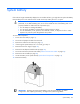
Table Of Contents
- HP ProLiant SL210t Gen8 Server User Guide
- Abstract
- Notice
- Contents
- Component identification
- Operations
- Power up the nodes
- Power down the node
- Remove the node from the chassis
- Remove the 1U cable guard
- Install the 1U cable guard
- Remove the PCI riser cage
- Install the PCI riser cage
- Remove the 2U adapter board bracket
- Install the 2U adapter board bracket
- Remove the Mini-SAS cable
- Connect the Mini-SAS cable
- Remove the 2U air baffle
- Install the 2U air baffle
- Remove the 1U air baffle
- Install the 1U air baffle
- Setup
- Hardware options installation
- Introduction
- Processor option
- Memory options
- Expansion board options
- GPU power cable option
- Smart Array controller cable options
- Installing the Mini-SAS P222 cable in a 1U node
- Installing the Mini-SAS P222 cable in a 2U node
- Installing the Mini-SAS P430 cable in a 1U node
- Installing the Mini-SAS P430 cable in a 2U node
- Installing the Mini-SAS P420 SFF cable in a 1U node
- Installing the Mini-SAS P420 SFF cable in a 2U node
- Installing the Mini-SAS P420 LFF cable in a 1U node
- Installing the Mini-SAS P420 LFF cable in a 2U node
- Installing the Mini-SAS P830 cable in a 2U node
- Controller options
- HP Trusted Platform Module option
- Cabling
- Software and configuration utilities
- Troubleshooting
- System battery
- Regulatory information
- Electrostatic discharge
- Specifications
- Support and other resources
- Acronyms and abbreviations
- Documentation feedback
- Index
System battery 82
System battery
If the node no longer automatically displays the correct date and time, you might have to replace the battery
that provides power to the real-time clock. Under normal use, battery life is 5 to 10 years.
WARNING: The computer contains an internal lithium manganese dioxide, a vanadium
pentoxide, or an alkaline battery pack. A risk of fire and burns exists if the battery pack is not
properly handled. To reduce the risk of personal injury:
• Do not attempt to recharge the battery.
• Do not expose the battery to temperatures higher than 60°C (140°F).
• Do not disassemble, crush, puncture, short external contacts, or dispose of in fire or water.
• Replace only with the spare designated for this product.
To remove the component:
1. Power down the node (on page 17).
2. Disconnect all peripheral cables from the node.
3. Remove the node from the chassis (on page 17).
4. If removing the system battery from a 1U node, go to step 9.
5. Remove the PCI riser cage (on page 20).
6. Remove the 2U adapter board bracket (on page 22).
7. Disconnect and remove the Mini-SAS cable ("Remove the Mini-SAS cable" on page 23).
8. Remove the 2U air baffle (on page 26).
9. Locate the battery on the system board ("System board components" on page 12).
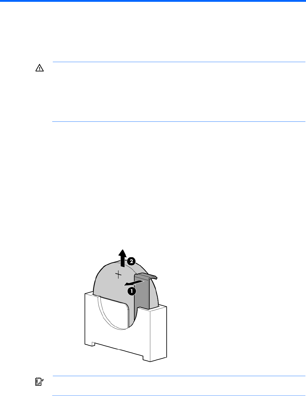
10. Remove the battery.
IMPORTANT: Replacing the system board battery resets the system ROM to its default
configuration. After replacing the battery, reconfigure the system through RBSU.