
User Manual
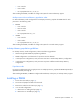
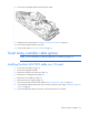
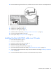
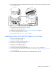
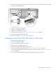
Table Of Contents
- HP ProLiant SL210t Gen8 Server User Guide
- Abstract
- Notice
- Contents
- Component identification
- Operations
- Power up the nodes
- Power down the node
- Remove the node from the chassis
- Remove the 1U cable guard
- Install the 1U cable guard
- Remove the PCI riser cage
- Install the PCI riser cage
- Remove the 2U adapter board bracket
- Install the 2U adapter board bracket
- Remove the Mini-SAS cable
- Connect the Mini-SAS cable
- Remove the 2U air baffle
- Install the 2U air baffle
- Remove the 1U air baffle
- Install the 1U air baffle
- Setup
- Hardware options installation
- Introduction
- Processor option
- Memory options
- Expansion board options
- GPU power cable option
- Smart Array controller cable options
- Installing the Mini-SAS P222 cable in a 1U node
- Installing the Mini-SAS P222 cable in a 2U node
- Installing the Mini-SAS P430 cable in a 1U node
- Installing the Mini-SAS P430 cable in a 2U node
- Installing the Mini-SAS P420 SFF cable in a 1U node
- Installing the Mini-SAS P420 SFF cable in a 2U node
- Installing the Mini-SAS P420 LFF cable in a 1U node
- Installing the Mini-SAS P420 LFF cable in a 2U node
- Installing the Mini-SAS P830 cable in a 2U node
- Controller options
- HP Trusted Platform Module option
- Cabling
- Software and configuration utilities
- Troubleshooting
- System battery
- Regulatory information
- Electrostatic discharge
- Specifications
- Support and other resources
- Acronyms and abbreviations
- Documentation feedback
- Index
Hardware options installation 41
o
First: A and B
o Last: D and E
o Do not populate slots C, F, G, H, or I.
After installing the DIMMs, use RBSU to configure the system for Mirrored Memory support.
Multi-processor Mirrored Memory population order
For Mirrored Memory mode configurations with multiple processors, populate the DIMM slots for each
processor in the following order:
• RDIMM
o First: A and B
o Next: D and E
o Last: G and H
o Do not populate slots C, F, or I.
• UDIMM
o First: A and B
o Last: D and E
o Do not populate slots C, F, G, H, or I.
After installing the DIMMs, use RBSU to configure the system for mirrored memory support.
Lockstep Memory population guidelines
For Lockstep memory mode configurations, observe the following guidelines:
• Observe the general DIMM slot population guidelines.
• DIMM configuration on all channels of a processor must be identical.
• In multi-processor configurations, each processor must have a valid Lockstep Memory configuration.
• In multi-processor configurations, each processor may have a different valid Lockstep Memory
configuration.
Population order
For memory configurations with a single processor or multiple processors, populate the DIMM sequentially in
alphabetical order (A through H).
After installing the DIMMs, use RBSU to configure Advanced ECC, online spare, or lockstep memory support.
Installing a DIMM
1. Power down the node (on page 17).
2. Disconnect all peripheral cables from the node.
3. Remove the node from the chassis (on page 17).
4. In a 1U node configuration:
a. Remove the 1U cable guard (on page 18).
b. Remove the 1U air baffle (on page 27).