
User Manual

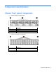
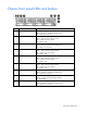
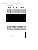
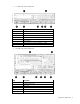
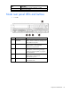
Table Of Contents
- HP ProLiant SL210t Gen8 Server User Guide
- Abstract
- Notice
- Contents
- Component identification
- Operations
- Power up the nodes
- Power down the node
- Remove the node from the chassis
- Remove the 1U cable guard
- Install the 1U cable guard
- Remove the PCI riser cage
- Install the PCI riser cage
- Remove the 2U adapter board bracket
- Install the 2U adapter board bracket
- Remove the Mini-SAS cable
- Connect the Mini-SAS cable
- Remove the 2U air baffle
- Install the 2U air baffle
- Remove the 1U air baffle
- Install the 1U air baffle
- Setup
- Hardware options installation
- Introduction
- Processor option
- Memory options
- Expansion board options
- GPU power cable option
- Smart Array controller cable options
- Installing the Mini-SAS P222 cable in a 1U node
- Installing the Mini-SAS P222 cable in a 2U node
- Installing the Mini-SAS P430 cable in a 1U node
- Installing the Mini-SAS P430 cable in a 2U node
- Installing the Mini-SAS P420 SFF cable in a 1U node
- Installing the Mini-SAS P420 SFF cable in a 2U node
- Installing the Mini-SAS P420 LFF cable in a 1U node
- Installing the Mini-SAS P420 LFF cable in a 2U node
- Installing the Mini-SAS P830 cable in a 2U node
- Controller options
- HP Trusted Platform Module option
- Cabling
- Software and configuration utilities
- Troubleshooting
- System battery
- Regulatory information
- Electrostatic discharge
- Specifications
- Support and other resources
- Acronyms and abbreviations
- Documentation feedback
- Index

Contents 3
Contents
Component identification ............................................................................................................... 6
Chassis front panel components ..................................................................................................................... 6
Chassis front panel LEDs and buttons.............................................................................................................. 7
Node rear panel components ........................................................................................................................ 8
Node rear panel LEDs and buttons ............................................................................................................... 10
System board components .......................................................................................................................... 12
DIMM slots ...................................................................................................................................... 12
NMI functionality ............................................................................................................................. 13
System maintenance switch ............................................................................................................... 14
Drive bay numbering .................................................................................................................................. 14
Hot-plug drive LED definitions ...................................................................................................................... 16
Operations................................................................................................................................. 17
Power up the nodes .................................................................................................................................... 17
Power down the node ................................................................................................................................. 17
Remove the node from the chassis ................................................................................................................ 17
Remove the 1U cable guard ........................................................................................................................ 18
Install the 1U cable guard ........................................................................................................................... 19
Remove the PCI riser cage ........................................................................................................................... 20
Install the PCI riser cage .............................................................................................................................. 21
Remove the 2U adapter board bracket ......................................................................................................... 22
Install the 2U adapter board bracket ............................................................................................................ 23
Remove the Mini-SAS cable ......................................................................................................................... 23
Connect the Mini-SAS cable ........................................................................................................................ 24
Remove the 2U air baffle ............................................................................................................................ 26
Install the 2U air baffle ............................................................................................................................... 26
Remove the 1U air baffle ............................................................................................................................ 27
Install the 1U air baffle ............................................................................................................................... 28
Setup ......................................................................................................................................... 29
Optional installation services ....................................................................................................................... 29
Rack planning resources ............................................................................................................................. 29
Configuring the chassis ............................................................................................................................... 29
Installing hardware options ......................................................................................................................... 30
Installing a node into the chassis .................................................................................................................. 30
Powering on and selecting boot options ....................................................................................................... 30
Installing the system software ....................................................................................................................... 31
Registering the server.................................................................................................................................. 31
Hardware options installation ....................................................................................................... 32
Introduction ............................................................................................................................................... 32
Processor option......................................................................................................................................... 32
Memory options ......................................................................................................................................... 37
DIMM identification .......................................................................................................................... 37
Single-rank and dual-rank DIMMs ...................................................................................................... 37
Memory subsystem architecture ......................................................................................................... 38
Memory configurations ..................................................................................................................... 38