
User Manual
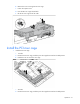
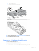
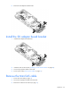
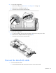
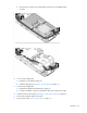
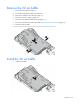
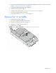
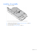
Table Of Contents
- HP ProLiant SL210t Gen8 Server User Guide
- Abstract
- Notice
- Contents
- Component identification
- Operations
- Power up the nodes
- Power down the node
- Remove the node from the chassis
- Remove the 1U cable guard
- Install the 1U cable guard
- Remove the PCI riser cage
- Install the PCI riser cage
- Remove the 2U adapter board bracket
- Install the 2U adapter board bracket
- Remove the Mini-SAS cable
- Connect the Mini-SAS cable
- Remove the 2U air baffle
- Install the 2U air baffle
- Remove the 1U air baffle
- Install the 1U air baffle
- Setup
- Hardware options installation
- Introduction
- Processor option
- Memory options
- Expansion board options
- GPU power cable option
- Smart Array controller cable options
- Installing the Mini-SAS P222 cable in a 1U node
- Installing the Mini-SAS P222 cable in a 2U node
- Installing the Mini-SAS P430 cable in a 1U node
- Installing the Mini-SAS P430 cable in a 2U node
- Installing the Mini-SAS P420 SFF cable in a 1U node
- Installing the Mini-SAS P420 SFF cable in a 2U node
- Installing the Mini-SAS P420 LFF cable in a 1U node
- Installing the Mini-SAS P420 LFF cable in a 2U node
- Installing the Mini-SAS P830 cable in a 2U node
- Controller options
- HP Trusted Platform Module option
- Cabling
- Software and configuration utilities
- Troubleshooting
- System battery
- Regulatory information
- Electrostatic discharge
- Specifications
- Support and other resources
- Acronyms and abbreviations
- Documentation feedback
- Index
Operations 25
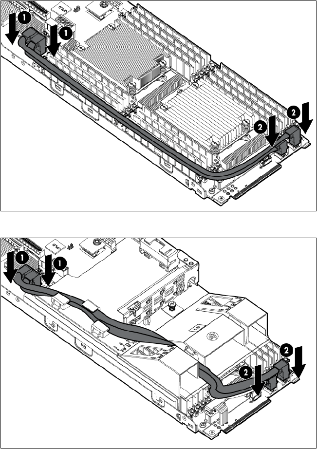
b.
Connect the two ends to the corresponding connectors on the adapter board.
1U node
2U node
2. In a 1U node configuration:
a. Install the 1U air baffle (on page 28).
b. Install the cable guard ("Install the 1U cable guard" on page 19).
3. In a 2U node configuration:
a. Install the 2U adapter board bracket (on page 23).
b. If a GPU is installed, connect the 2U adapter cable to the GPU power cable.
4. Install the node into the chassis ("Installing a node into the chassis" on page 30).
5. Connect all peripheral cables to the node.
6. Power up the node ("Power up the nodes" on page 17).