
User Manual
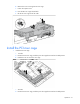
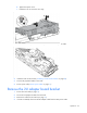
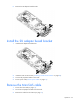
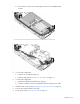
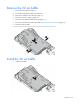
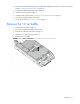
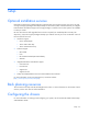
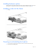
Table Of Contents
- HP ProLiant SL210t Gen8 Server User Guide
- Abstract
- Notice
- Contents
- Component identification
- Operations
- Power up the nodes
- Power down the node
- Remove the node from the chassis
- Remove the 1U cable guard
- Install the 1U cable guard
- Remove the PCI riser cage
- Install the PCI riser cage
- Remove the 2U adapter board bracket
- Install the 2U adapter board bracket
- Remove the Mini-SAS cable
- Connect the Mini-SAS cable
- Remove the 2U air baffle
- Install the 2U air baffle
- Remove the 1U air baffle
- Install the 1U air baffle
- Setup
- Hardware options installation
- Introduction
- Processor option
- Memory options
- Expansion board options
- GPU power cable option
- Smart Array controller cable options
- Installing the Mini-SAS P222 cable in a 1U node
- Installing the Mini-SAS P222 cable in a 2U node
- Installing the Mini-SAS P430 cable in a 1U node
- Installing the Mini-SAS P430 cable in a 2U node
- Installing the Mini-SAS P420 SFF cable in a 1U node
- Installing the Mini-SAS P420 SFF cable in a 2U node
- Installing the Mini-SAS P420 LFF cable in a 1U node
- Installing the Mini-SAS P420 LFF cable in a 2U node
- Installing the Mini-SAS P830 cable in a 2U node
- Controller options
- HP Trusted Platform Module option
- Cabling
- Software and configuration utilities
- Troubleshooting
- System battery
- Regulatory information
- Electrostatic discharge
- Specifications
- Support and other resources
- Acronyms and abbreviations
- Documentation feedback
- Index
Operations 21
b.
Remove the screw securing the PCI riser cage.
c. Loosen the captive screw.
d. Press the PCI riser cage release latch.
e. Lift the PCI riser cage out of the node.
Install the PCI riser cage
1. Install the PCI riser cage:
o 1U node
a. Position the PCI riser cage, and then press the cage downward into locked position.
b. Install the screw to secure the riser cage.
o 2U node
a. Position the PCI riser cage, and then press the cage downward into locked position.