
User Manual
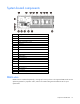
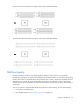
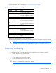
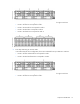
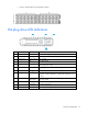
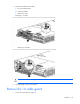
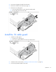
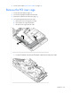
Table Of Contents
- HP ProLiant SL210t Gen8 Server User Guide
- Abstract
- Notice
- Contents
- Component identification
- Operations
- Power up the nodes
- Power down the node
- Remove the node from the chassis
- Remove the 1U cable guard
- Install the 1U cable guard
- Remove the PCI riser cage
- Install the PCI riser cage
- Remove the 2U adapter board bracket
- Install the 2U adapter board bracket
- Remove the Mini-SAS cable
- Connect the Mini-SAS cable
- Remove the 2U air baffle
- Install the 2U air baffle
- Remove the 1U air baffle
- Install the 1U air baffle
- Setup
- Hardware options installation
- Introduction
- Processor option
- Memory options
- Expansion board options
- GPU power cable option
- Smart Array controller cable options
- Installing the Mini-SAS P222 cable in a 1U node
- Installing the Mini-SAS P222 cable in a 2U node
- Installing the Mini-SAS P430 cable in a 1U node
- Installing the Mini-SAS P430 cable in a 2U node
- Installing the Mini-SAS P420 SFF cable in a 1U node
- Installing the Mini-SAS P420 SFF cable in a 2U node
- Installing the Mini-SAS P420 LFF cable in a 1U node
- Installing the Mini-SAS P420 LFF cable in a 2U node
- Installing the Mini-SAS P830 cable in a 2U node
- Controller options
- HP Trusted Platform Module option
- Cabling
- Software and configuration utilities
- Troubleshooting
- System battery
- Regulatory information
- Electrostatic discharge
- Specifications
- Support and other resources
- Acronyms and abbreviations
- Documentation feedback
- Index

Operations 17
Operations
Power up the nodes
The SL Chassis Firmware initiates an automatic power-up sequence when the nodes are installed. If the
default setting is changed, use one of the following methods to power up each node:
• Use a virtual power button selection through iLO.
• Press and release the Power On/Standby button.
When the node goes from the standby mode to the full power mode, the node power LED changes from
amber to green.
For more information about iLO, see the HP website (http://www.hp.com/go/ilo).
Power down the node
Before powering down the node for any upgrade or maintenance procedures, perform a backup of critical
server data and programs.
IMPORTANT: When the node is in standby mode, auxiliary power is still being provided to the
system.
To power down the node, use one of the following methods:
• Press and release the Power On/Standby button.
This method initiates a controlled shutdown of applications and the OS before the node enters standby
mode.
• Press and hold the Power On/Standby button for more than 4 seconds to force the node to enter
standby mode.
This method forces the node to enter standby mode without properly exiting applications and the OS.
If an application stops responding, you can use this method to force a shutdown.
• Use a virtual power button selection through iLO.
This method initiates a controlled remote shutdown of applications and the OS before the node enters
standby mode.
Before proceeding, verify the node is in standby mode by observing that the system power LED is amber.
Remove the node from the chassis
CAUTION: To avoid damage to the node, always support the bottom of the node when removing
it from the chassis.
1. Power down the node (on page 17).
2. Disconnect all peripheral cables from the node.