
User Manual
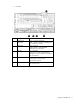
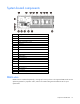
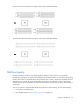
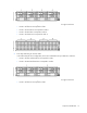
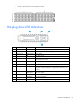
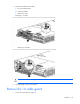
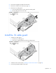
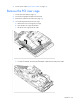
Table Of Contents
- HP ProLiant SL210t Gen8 Server User Guide
- Abstract
- Notice
- Contents
- Component identification
- Operations
- Power up the nodes
- Power down the node
- Remove the node from the chassis
- Remove the 1U cable guard
- Install the 1U cable guard
- Remove the PCI riser cage
- Install the PCI riser cage
- Remove the 2U adapter board bracket
- Install the 2U adapter board bracket
- Remove the Mini-SAS cable
- Connect the Mini-SAS cable
- Remove the 2U air baffle
- Install the 2U air baffle
- Remove the 1U air baffle
- Install the 1U air baffle
- Setup
- Hardware options installation
- Introduction
- Processor option
- Memory options
- Expansion board options
- GPU power cable option
- Smart Array controller cable options
- Installing the Mini-SAS P222 cable in a 1U node
- Installing the Mini-SAS P222 cable in a 2U node
- Installing the Mini-SAS P430 cable in a 1U node
- Installing the Mini-SAS P430 cable in a 2U node
- Installing the Mini-SAS P420 SFF cable in a 1U node
- Installing the Mini-SAS P420 SFF cable in a 2U node
- Installing the Mini-SAS P420 LFF cable in a 1U node
- Installing the Mini-SAS P420 LFF cable in a 2U node
- Installing the Mini-SAS P830 cable in a 2U node
- Controller options
- HP Trusted Platform Module option
- Cabling
- Software and configuration utilities
- Troubleshooting
- System battery
- Regulatory information
- Electrostatic discharge
- Specifications
- Support and other resources
- Acronyms and abbreviations
- Documentation feedback
- Index
Component identification 14
For more information, see the HP website (http://www.hp.com/support/NMI).
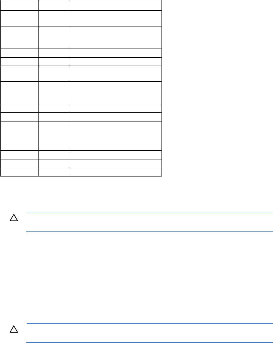
System maintenance switch
Position Default Function
S1
Off Off = iLO security is enabled.
On = iLO security is disabled.
S2
Off Off = System configuration can be
changed.
On = System configuration is locked.
S3
Off Reserved
S4
Off Reserved
S5
Off Off = Power-on password is enabled.
On = Power-on password is disabled.
S6
Off Off = No function
On = ROM reads system configuration
as invalid.
S7
— Reserved
S8
— Reserved
S9
— Off = PCIe 64-bit BAR function (large
BAR) is disabled.
On = PCIe 64-bit BAR function (large
BAR) is enabled.
S10
— Reserved
S11
— Reserved
S12
— Reserved
To access the redundant ROM, set S1, S5, and S6 to on.
When the system maintenance switch position 6 is set to the On position, the system is prepared to erase all
system configuration settings from both CMOS and NVRAM.
CAUTION: Clearing CMOS and/or NVRAM deletes configuration information. Be sure to
properly configure the server or data loss could occur.
Drive bay numbering
• Drive bay numbering for four 1U nodes
In an 8-drive bay LFF drive configuration, drives are numbered from top to bottom in each box.
o Drives in the first box correspond to node 1.
o Drives in the second box correspond to node 2.
o Drives in the third box correspond to node 3.
o Drives in the fourth box correspond to node 4.
CAUTION: To prevent improper cooling and thermal damage, do not operate the chassis unless
all bays are populated with a component or a blank.