
User Manual
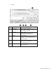
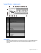
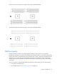
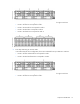
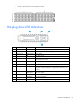
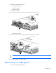
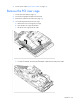
Table Of Contents
- HP ProLiant SL210t Gen8 Server User Guide
- Abstract
- Notice
- Contents
- Component identification
- Operations
- Power up the nodes
- Power down the node
- Remove the node from the chassis
- Remove the 1U cable guard
- Install the 1U cable guard
- Remove the PCI riser cage
- Install the PCI riser cage
- Remove the 2U adapter board bracket
- Install the 2U adapter board bracket
- Remove the Mini-SAS cable
- Connect the Mini-SAS cable
- Remove the 2U air baffle
- Install the 2U air baffle
- Remove the 1U air baffle
- Install the 1U air baffle
- Setup
- Hardware options installation
- Introduction
- Processor option
- Memory options
- Expansion board options
- GPU power cable option
- Smart Array controller cable options
- Installing the Mini-SAS P222 cable in a 1U node
- Installing the Mini-SAS P222 cable in a 2U node
- Installing the Mini-SAS P430 cable in a 1U node
- Installing the Mini-SAS P430 cable in a 2U node
- Installing the Mini-SAS P420 SFF cable in a 1U node
- Installing the Mini-SAS P420 SFF cable in a 2U node
- Installing the Mini-SAS P420 LFF cable in a 1U node
- Installing the Mini-SAS P420 LFF cable in a 2U node
- Installing the Mini-SAS P830 cable in a 2U node
- Controller options
- HP Trusted Platform Module option
- Cabling
- Software and configuration utilities
- Troubleshooting
- System battery
- Regulatory information
- Electrostatic discharge
- Specifications
- Support and other resources
- Acronyms and abbreviations
- Documentation feedback
- Index
Component identification 12
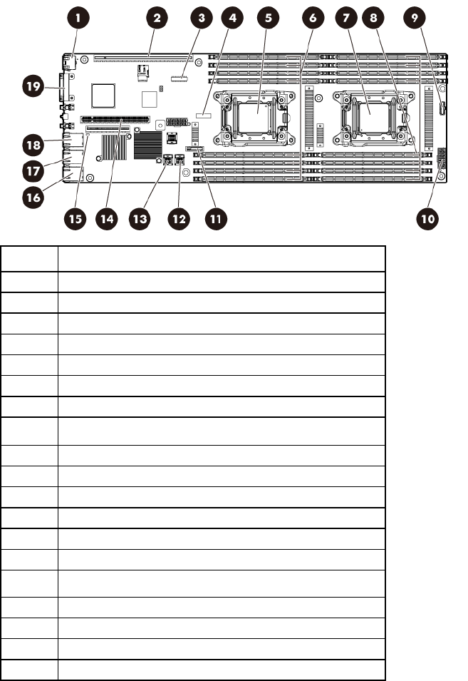
System board components
Item Description
1
Serial 2 connector (RJ45)
2
PCIe slot
3
TPM connector
4
System maintenance switch
5
Processor 1
6
Processor 1 DIMM slots
7
Processor 2
8
Processor 2 DIMM slots
9
RPS connector
10
Power connector
11
System battery
12
SAS connector 2
13
SAS connector 1
14
FelxibleLOM slot
15
NMI header
16
NIC connector 2
17
NIC connector 1
18
iLO connector
19
SUV connector (1 serial/ 2 USB 2.0/ 1 video)
DIMM slots
DIMM slots are numbered sequentially (1 through 8) for each processor. The supported AMP modes use the
alpha assignments for population order, and the slot numbers designate the DIMM slot ID for spare
replacement.