HP ProLiant SL210t Gen8 Server User Guide Abstract This document is for the person who installs, administers, and troubleshoots servers and storage systems. HP assumes you are qualified in the servicing of computer equipment and trained in recognizing hazards in products with hazardous energy levels.
© Copyright 2013, 2014 Hewlett-Packard Development Company, L.P. The information contained herein is subject to change without notice. The only warranties for HP products and services are set forth in the express warranty statements accompanying such products and services. Nothing herein should be construed as constituting an additional warranty. HP shall not be liable for technical or editorial errors or omissions contained herein. Microsoft® and Windows® are U.S.
Contents Component identification ............................................................................................................... 6 Chassis front panel components ..................................................................................................................... 6 Chassis front panel LEDs and buttons.............................................................................................................. 7 Node rear panel components .....................................
Memory population guidelines .......................................................................................................... 39 Installing a DIMM............................................................................................................................. 41 Expansion board options ............................................................................................................................ 42 Installing an expansion board .............................................
HP Smart Storage Administrator......................................................................................................... 77 ROMPaq utility................................................................................................................................. 77 Automatic Server Recovery ................................................................................................................ 77 USB support ........................................................................
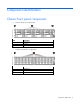
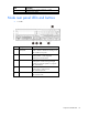
Component identification Chassis front panel components • 8-drive bay LFF drive configuration Item Description 1 Left bezel ear 2 LFF drives 3 Right bezel ear • 24-drive bay SFF drive configuration Item Description 1 Left bezel ear 2 SFF drives 3 Right bezel ear Component identification 6
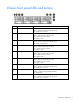
Chassis front panel LEDs and buttons Item Description Status 1 Power button/LED for node 2 Green = Node 2 is powered on. Amber = Node 2 is off and has standby power. Off = Node 2 has no power. 2 Health LED for node 2 3 Power button/LED for node 1 Green = Node 1 is powered on. Amber = Node 1 is off and has standby power. Off = Node 1 has no power. 4 Health LED for node 1 Green = Node 1 is operating normally. Amber = Non-critical error has occurred. Red = Critical error has occurred.
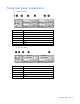
Node rear panel components • 1U node rear panel Item Description 1 RCM module 2 Power supply 1 3 Power supply 2 4 Node 4 5 Node 3 6 Node 2 7 Node 1 • 2U node rear panel Item Description 1 RCM module 2 Power supply 1 3 Power supply 2 4 Node 3 5 Node 1 Component identification 8
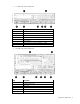
• 1U node rear panel components Item Description 1 PCI slot cover 2 FlexibleLOM slot cover 3 NIC 2 port 4 NIC 1 port 5 Serial number/iLO information pull tab 6 iLO connector 7 SUV connector (1 serial/ 2 USB 2.
Item Description 7 SUV connector (1 serial/ 2 USB 2.0/ 1 video) 8 Serial connector (RJ45) Node rear panel LEDs and buttons • 1U node Item Description Status 1 Node power button/LED Green = Node is powered on. Amber = Node is off and has standby power. Off = Node has no power. 2 Health LED Green = Normal. Flashing amber = Node degraded. Flashing red = Node critical. 3 UID LED Blue = Activated. Flashing blue = Node is being managed remotely, or firmware update is in progress.
• 2U node Item Description Status 1 Node power button/LED Green = Node is powered on. Amber = Node is off and has standby power. Off = Node has no power. 2 Health LED Green = Normal. Flashing amber = Node degraded. Flashing red = Node critical. 3 UID LED Blue = Activated. Flashing blue = Node is remotely being managed, or firmware update is in progress. Off = Deactivated. 4 NIC status LED Green = Activity exists. Flashing green = Activity exists. Off = No activity exists.
System board components Item Description 1 Serial 2 connector (RJ45) 2 PCIe slot 3 TPM connector 4 System maintenance switch 5 Processor 1 6 Processor 1 DIMM slots 7 Processor 2 8 Processor 2 DIMM slots 9 RPS connector 10 Power connector 11 System battery 12 SAS connector 2 13 SAS connector 1 14 FelxibleLOM slot 15 NMI header 16 NIC connector 2 17 NIC connector 1 18 iLO connector 19 SUV connector (1 serial/ 2 USB 2.
The HP ProLiant SL210t Gen8 Server supports 2DPC using 1600 MHz DIMMs. The HP ProLiant SL210t Gen8 Server supports 1DPC using 1866 MHz DIMMs. NMI functionality An NMI crash dump creates a crash dump log before resetting a system which is not responding. Crash dump log analysis is an essential part of diagnosing reliability problems, such as failures of operating systems, device drivers, and applications.
For more information, see the HP website (http://www.hp.com/support/NMI). System maintenance switch Position Default Function S1 Off Off = iLO security is enabled. On = iLO security is disabled. S2 Off Off = System configuration can be changed. On = System configuration is locked. S3 Off Reserved S4 Off Reserved S5 Off Off = Power-on password is enabled. On = Power-on password is disabled. S6 Off Off = No function On = ROM reads system configuration as invalid.
In a 24-drive bay SFF drive configuration, drives are numbered from left to right in each box. • o Drives in the first box correspond to node 1. o Drives in the second box correspond to node 2. o Drives in the third box correspond to node 3. o Drives in the fourth box correspond to node 4. Drive bay numbering for two 2U nodes In an 8-drive bay LFF drive configuration, drives are numbered from top to bottom in each box. o Drives in the first and second box correspond to node 1.
o Drives in the second box correspond to node 3. Hot-plug drive LED definitions Item LED Status Definition 1 Locate Solid blue The drive is being identified by a host application. Flashing blue The drive carrier firmware is being updated or requires an update. Rotating green Drive activity Off No drive activity Solid white Do not remove the drive. Removing the drive causes one or more of the logical drives to fail. Off Removing the drive does not cause a logical drive to fail.
Operations Power up the nodes The SL Chassis Firmware initiates an automatic power-up sequence when the nodes are installed. If the default setting is changed, use one of the following methods to power up each node: • Use a virtual power button selection through iLO. • Press and release the Power On/Standby button. When the node goes from the standby mode to the full power mode, the node power LED changes from amber to green. For more information about iLO, see the HP website (http://www.hp.
3. Remove the node from the chassis: a. Press the release button. b. Lower the handle. c. Remove the node. Removing a 1U node Removing a 2U node CAUTION: To avoid damage to the device, do not use the removal handle to carry it. 4. Place the node on a flat, level surface. Remove the 1U cable guard 1. Power down the node (on page 17).
2. Disconnect all peripheral cables from the node. 3. Remove the node from the chassis (on page 17). 4. Remove the 1U cable guard: a. Press the release latches on each side of the cable guard. b. Lift the cable guard out of the node. Install the 1U cable guard 1. Install the 1U cable guard: a. Position the 1U cable guard. b. Press the 1U cable guard downward into locked position. 2. Install the node into the chassis ("Installing a node into the chassis" on page 30). 3.
4. Power up the node ("Power up the nodes" on page 17). Remove the PCI riser cage 1. Power down the node (on page 17). 2. Disconnect all peripheral cables from the node. 3. Remove the node from the chassis (on page 17). 4. (1U node only) Remove the PCI riser cage: a. Remove the screw securing the riser cage. b. Press the PCI riser cage release latch. c. 5. Lift the PCI riser cage out of the node. (2U node only) Remove the PCI riser cage: a.
b. Remove the screw securing the PCI riser cage. c. Loosen the captive screw. d. Press the PCI riser cage release latch. e. Lift the PCI riser cage out of the node. Install the PCI riser cage 1. Install the PCI riser cage: o 1U node a. Position the PCI riser cage, and then press the cage downward into locked position. b. Install the screw to secure the riser cage. o 2U node a. Position the PCI riser cage, and then press the cage downward into locked position.
b. Tighten the captive screw. c. Install the screw to secure the riser cage. d. If a GPU is installed, connect the 2U adapter cable to the GPU power cable. 2. Install the node into the chassis ("Installing a node into the chassis" on page 30). 3. Connect all peripheral cables to the node. 4. Power up the node ("Power up the nodes" on page 17). Remove the 2U adapter board bracket 1. Power down the node (on page 17). 2. Disconnect all peripheral cables from the node. 3.
5. Remove the 2U adapter board bracket. Install the 2U adapter board bracket 1. Install the 2U adapter board bracket. 2. Install the node into the chassis ("Installing a node into the chassis" on page 30). 3. Connect all peripheral cables to the node. 4. Power up the node ("Power up the nodes" on page 17). Remove the Mini-SAS cable 1. Power down the node (on page 17). 2. Disconnect all peripheral cables from the node. 3. Remove the node from the chassis (on page 17).
4. In a 1U node configuration: a. Remove the cable guard ("Remove the 1U cable guard" on page 18). b. Remove the 1U air baffle (on page 27). c. 5. Disconnect and remove the Mini-SAS cable. In a 2U node configuration: a. If a GPU is installed, disconnect the 2U adapter cable from the GPU power cable. b. Remove the 2U adapter board bracket (on page 22). c. Disconnect and remove the Mini-SAS cable. Connect the Mini-SAS cable 1. Connect the Mini-SAS cable: a.
b. Connect the two ends to the corresponding connectors on the adapter board. 1U node 2U node 2. In a 1U node configuration: a. Install the 1U air baffle (on page 28). b. Install the cable guard ("Install the 1U cable guard" on page 19). 3. In a 2U node configuration: a. Install the 2U adapter board bracket (on page 23). b. If a GPU is installed, connect the 2U adapter cable to the GPU power cable. 4. Install the node into the chassis ("Installing a node into the chassis" on page 30). 5.
Remove the 2U air baffle 1. Power down the node (on page 17). 2. Disconnect all peripheral cables from the node. 3. Remove the node from the chassis (on page 17). 4. Remove the PCI riser cage (on page 20). 5. Remove the 2U adapter board bracket (on page 22). 6. Disconnect and remove the Mini-SAS cable ("Remove the Mini-SAS cable" on page 23). 7. Remove the 2U air baffle. Install the 2U air baffle 1. Install the air baffle.
2. Route the Mini-SAS cable through the air baffle cable management, and then connect it to the system board ("Connect the Mini-SAS cable" on page 24). 3. Install the 2U adapter board bracket (on page 23). 4. Install the PCI riser cage (on page 21). 5. Install the node into the chassis ("Installing a node into the chassis" on page 30). 6. Connect all peripheral cables to the node. 7. Power up the node ("Power up the nodes" on page 17). Remove the 1U air baffle 1.
Install the 1U air baffle 1. Install the 1U air baffle. 2. Install the 1U cable guard (on page 19). 3. Install the node into the chassis ("Installing a node into the chassis" on page 30). 4. Connect all peripheral cables to the node. 5. Power up the node ("Power up the nodes" on page 17).
Setup Optional installation services Delivered by experienced, certified engineers, HP Care Pack services help you keep your servers up and running with support packages tailored specifically for HP ProLiant systems. HP Care Packs let you integrate both hardware and software support into a single package. A number of service level options are available to meet your needs.
Installing hardware options Install any hardware options before initializing the node. For options installation information, see the option documentation. For node-specific information, see "Hardware options installation (on page 32)." Installing a node into the chassis • 1U node • 2U node Powering on and selecting boot options 1. Connect the Ethernet cable between the network connector on the node and a network jack. 2. Press the Power On/Standby button.
3. During the initial boot: o To modify the server configuration ROM default settings, press F9 when prompted from the start up sequence to enter the RBSU. By default, RBSU runs in the English language. o If you do not need to modify the server configuration and are ready to install the system software, press F10 to access Intelligent Provisioning.
Hardware options installation Introduction If more than one option is being installed, read the installation instructions for all the hardware options and identify similar steps to streamline the installation process. WARNING: To reduce the risk of personal injury from hot surfaces, allow the drives and the internal system components to cool before touching them. CAUTION: To prevent damage to electrical components, properly ground the server before beginning any installation procedure.
a. Remove the PCI riser cage (on page 20). b. Remove the 2U adapter board bracket (on page 22). c. Disconnect and remove the Mini-SAS cable ("Remove the Mini-SAS cable" on page 23). d. Remove the 2U air baffle (on page 26). 7. Open each of the processor locking levers in the order indicated, and then open the processor retaining bracket. 8. Remove the clear processor socket cover. Retain the processor socket cover for future use.
9. Install the processor. Verify that the processor is fully seated in the processor retaining bracket by visually inspecting the processor installation guides on either side of the processor. THE PINS ON THE SYSTEM BOARD ARE VERY FRAGILE AND EASILY DAMAGED. CAUTION: THE PINS ON THE SYSTEM BOARD ARE VERY FRAGILE AND EASILY DAMAGED. To avoid damage to the system board, do not touch the processor or the processor socket contacts. 10. Close the processor retaining bracket.
11. Press and hold the processor retaining bracket in place, and then close each processor locking lever. Press only in the area indicated on the processor retaining bracket. CAUTION: Always use a new heatsink when replacing processors. Failure to use new components can cause damage to the processor. 12. Remove the thermal interface protective cover from the heatsink. CAUTION: Heatsink retaining screws should be tightened or loosened in diagonally opposite pairs (in an "X" pattern).
a. Position the heatsink on the processor backplate. b. Tighten one pair of diagonally opposite screws halfway, and then tighten the other pair of screws. c. 14. Finish the installation by completely tightening the screws in the same sequence. In a 1U node configuration: a. Install the 1U air baffle (on page 28). b. Install the 1U cable guard (on page 19). 15. In a 2U node configuration: a. Install the 2U air baffle (on page 26). b. Connect the Mini-SAS cable (on page 24). c.
Memory options DIMM identification To determine DIMM characteristics, use the label attached to the DIMM and the following illustration and table. Item Description Definition 1 Size — 2 Rank 1R = Single-rank 2R = Dual-rank 4R = Quad-rank 3 Data width x4 = 4-bit x8 = 8-bit 4 Voltage rating L = Low voltage (1.35v) U = Ultra low voltage (1.
• Single-rank DIMM—One set of memory chips that is accessed while writing to or reading from the memory. • Dual-rank DIMM—Two single-rank DIMMs on the same module, with only one rank accessible at a time. The server memory control subsystem selects the proper rank within the DIMM when writing to or reading from the DIMM. Dual-rank DIMMs provide the greatest capacity with the existing memory technology.
Advanced ECC memory configuration Advanced ECC memory is the default memory protection mode for this node. Standard ECC can correct single-bit memory errors and detect multi-bit memory errors. When multi-bit errors are detected using Standard ECC, the error is signaled to the node and causes the node to halt. Advanced ECC protects the node against some multi-bit memory errors.
• When one processor is installed, install DIMMs in sequential alphabetic order: A, B, C, D, E, F, and so forth. • When two processors are installed, install the DIMMs in sequential alphabetic order balanced between the two processors: P1-A, P2-A, P1-B, P2-B, P1-C, P2-C, and so forth. • For DIMM spare replacement, install the DIMMs per slot number as instructed by the system software.
o First: A and B o Last: D and E o Do not populate slots C, F, G, H, or I. After installing the DIMMs, use RBSU to configure the system for Mirrored Memory support. Multi-processor Mirrored Memory population order For Mirrored Memory mode configurations with multiple processors, populate the DIMM slots for each processor in the following order: • • RDIMM o First: A and B o Next: D and E o Last: G and H o Do not populate slots C, F, or I.
c. 5. Disconnect and remove the Mini-SAS cable ("Remove the Mini-SAS cable" on page 23). In a 2U node configuration: a. Remove the PCI riser cage (on page 20). b. Remove the 2U adapter board bracket (on page 22). c. Disconnect and remove the Mini-SAS cable ("Remove the Mini-SAS cable" on page 23). d. Remove the 2U air baffle (on page 26). 6. Open the DIMM slot latches. 7. Install the DIMM. 8. In a 1U node configuration: a. Connect the Mini-SAS cable (on page 24). b.
NOTE: If a GPU is installed in a 2U node, only one low-profile expansion board can be installed. 1. Power down the node (on page 17). 2. Disconnect all peripheral cables from the node. 3. Remove the node from the chassis (on page 17). 4. Remove the PCI riser cage (on page 20). 5. Install the expansion board. o 1U node o 2U node 6. Install the PCI riser cage (on page 21). 7. Install the node into the chassis. ("Installing a node into the chassis" on page 30) 8.
a. Connect the GPU power cable to the GPU. b. Connect the GPU power cable to the PCI riser board. 6. Install the GPU into the PCI riser cage. 7. Install the PCI riser cage (on page 21).
8. Connect the 2U adapter cable to the GPU power cable. 9. Install the node into the chassis ("Installing a node into the chassis" on page 30). 10. Connect all peripheral cables to the node. 11. Power up the node ("Power up the nodes" on page 17). Smart Array controller cable options NOTE: For more information on cabling configurations, see Cabling (on page 59). Installing the Mini-SAS P222 cable in a 1U node 1. Power down the node (on page 17). 2. Disconnect all peripheral cables. 3.
10. Route the cable along the side of the server, and then connect it to the connector on the adapter board. 11. Install the PCI riser cage (on page 21). 12. Install the 1U air baffle (on page 28). 13. Install the 1U cable guard (on page 19). 14. Install the node into the chassis ("Installing a node into the chassis" on page 30). 15. Connect all peripheral cables to the node. 16. Power up the node ("Power up the nodes" on page 17). Installing the Mini-SAS P222 cable in a 2U node 1.
9. Route the cable through the air baffle, and then connect the cable to the connectors on the adapter board. 10. Install the 2U adapter board bracket (on page 23). 11. Install the PCI riser cage (on page 21). 12. Install the node into the chassis ("Installing a node into the chassis" on page 30). 13. Connect all peripheral cables to the node. 14. Power up the node ("Power up the nodes" on page 17). Installing the Mini-SAS P430 cable in a 1U node 1. Power down the node (on page 17). 2.
10. Route the cable along the side of the server, and then connect the two ends to the corresponding connectors on the adapter board. 11. Install the PCI riser cage (on page 21). 12. Install the 1U air baffle (on page 28). 13. Install the 1U cable guard (on page 19). 14. Install the node into the chassis ("Installing a node into the chassis" on page 30). 15. Connect all peripheral cables to the node. 16. Power up the node ("Power up the nodes" on page 17).
9. Route the cable through the air baffle, and then connect the two ends to the corresponding connectors on the adapter board. 10. Install the 2U adapter board bracket (on page 23). 11. Install the PCI riser cage (on page 21). 12. Install the node into the chassis ("Installing a node into the chassis" on page 30). 13. Connect all peripheral cables to the node. 14. Power up the node ("Power up the nodes" on page 17). Installing the Mini-SAS P420 SFF cable in a 1U node 1.
10. Route the cable along the side of the server, and then connect the two cable ends to the corresponding connectors on the adapter board. 11. Install the PCI riser cage (on page 21). 12. Install the 1U air baffle (on page 28). 13. Install the 1U cable guard (on page 19). 14. Install the node into the chassis ("Installing a node into the chassis" on page 30). 15. Connect all peripheral cables to the node. 16. Power up the node ("Power up the nodes" on page 17).
9. Route the cable through the air baffle, and then connect the two cable ends to the corresponding connectors on the adapter board. 10. Install the 2U adapter board bracket (on page 23). 11. Install the PCI riser cage (on page 21). 12. Install the node into the chassis ("Installing a node into the chassis" on page 30). 13. Connect all peripheral cables to the node. 14. Power up the node ("Power up the nodes" on page 17). Installing the Mini-SAS P420 LFF cable in a 1U node 1.
10. Route the cable along the side of the server, and then connect the cable to the connector on the adapter board. 11. Install the PCI riser cage (on page 21). 12. Install the 1U air baffle (on page 28). 13. Install the 1U cable guard (on page 19). 14. Install the node into the chassis ("Installing a node into the chassis" on page 30). 15. Connect all peripheral cables to the node. 16. Power up the node ("Power up the nodes" on page 17). Installing the Mini-SAS P420 LFF cable in a 2U node 1.
9. Route the cable through the air baffle, and then connect the cable to the connector on the adapter board. 10. Install the 2U adapter board bracket (on page 23). 11. Install the PCI riser cage (on page 21). 12. Install the node into the chassis ("Installing a node into the chassis" on page 30). 13. Connect all peripheral cables to the node. 14. Power up the node ("Power up the nodes" on page 17). Installing the Mini-SAS P830 cable in a 2U node 1. Power down the node (on page 17). 2.
d. Route the straight cable through the air baffle, and then connect the two ends of the cable to the corresponding connectors on the top adapter board. 9. Install the PCI riser cage (on page 21). 10. Install the node into the chassis ("Installing a node into the chassis" on page 30). 11. Connect all peripheral cables to the node. 12. Power up the node ("Power up the nodes" on page 17). Controller options The nodes include an embedded HP Smart Array B120i controller.
6. Install the FBWC capacitor pack into the holder mounted in the node. 7. Connect the FBWC cable to the cache module on the system board or to the controller card. 8. Install the PCI riser cage (on page 21). 9. Install the node into the chassis ("Installing a node into the chassis" on page 30). 10. Connect all peripheral cables to the node. 11. Power up the node ("Power up the nodes" on page 17).
Enabling the TPM requires accessing RBSU. For more information about RBSU, see the HP website (http://www.hp.com/support/rbsu). TPM installation requires the use of drive encryption technology, such as the Microsoft Windows BitLocker Drive Encryption feature. For more information on BitLocker, see the Microsoft website (http://www.microsoft.com). CAUTION: Always observe the guidelines in this document. Failure to follow these guidelines can cause hardware damage or halt data access.
5. Install the TPM board. Press down on the connector to seat the board ("System board components" on page 12). 6. Install the TPM security rivet by pressing the rivet firmly into the system board. 7. Install the PCI riser cage (on page 21). 8. Install the node into the chassis ("Installing a node into the chassis" on page 30). 9. Connect all peripheral cables to the node. 10. Power up the node ("Power up the nodes" on page 17).
• Always store the recovery key/password in multiple locations. • Always store copies of the recovery key/password away from the node. • Do not save the recovery key/password on the encrypted hard drive. Enabling the Trusted Platform Module 1. When prompted during the start-up sequence, access RBSU by pressing the F9 key. 2. From the Main Menu, select Server Security. 3. From the Server Security Menu, select Trusted Platform Module. 4.
Cabling Cabling overview This section provides guidelines that help you make informed decisions about cabling the server and hardware options to optimize performance. For information on cabling peripheral components, refer to the white paper on high-density deployment at the HP website (http://www.hp.com/products/servers/platforms). CAUTION: When routing cables, always be sure that the cables are not in a position where they can be pinched or crimped.
• RPS cabling FBWC capacitor pack cabling • 1U node • 2U node Cabling 60
System board Mini-SAS cabling 1U node configuration • Two LFF drives per node • Six SFF drives per node Cabling 61
2U node configuration • Four LFF drives per node • Six SFF drives per node Cabling 62
GPU power cabling Mini-SAS P222 cabling • 1U node Cabling 63
• 2U node with two LFF drives per node Mini-SAS P420 LFF cabling • 1U node Cabling 64
• 2U node with four LFF drives per node Mini-SAS P420 SFF cabling • 1U node • 2U node Cabling 65
o Twelve SFF drives per node o Six SFF drives per node Cabling 66
Mini-SAS P430 cabling • 1U node • 2U node o Four LFF drives per node Cabling 67
o Twelve SFF drives per node o Six SFF drives per node Mini-SAS P830 cabling o 2U node with twelve SFF drives per node Cabling 68
Cabling 69
Software and configuration utilities Server mode The software and configuration utilities presented in this section operate in online mode, offline mode, or in both modes.
iLO enables and manages the Active Health System (on page 71) and also features Agentless Management. All key internal subsystems are monitored by iLO. SNMP alerts are sent directly by iLO regardless of the host operating system or even if no host operating system is installed. HP Insight Remote Support software (on page 74) is also available in HP iLO with no operating system software, drivers, or agents.
The data that is collected is managed according to the HP Data Privacy policy. For more information see the HP website (http://www.hp.com/go/privacy). The Active Health System log, in conjunction with the system monitoring provided by Agentless Management or SNMP Pass-thru, provides continuous monitoring of hardware and configuration changes, system status, and service alerts for various server components. The Agentless Management Service is available in the SPP, which is a disk image (.
see the Resources tab on the HP website (http://www.hp.com/go/ilo). For consolidated drive and firmware update packages, see the HP Systems and Server Software Management page on the HP website (http://www.hp.com/go/SmartUpdate).
HP Insight Remote Support software HP strongly recommends that you register your device for remote support to enable enhanced delivery of your HP Warranty, HP Care Pack Service, or HP contractual support agreement.
SPP can be used in an online mode on a Windows or Linux hosted operating system, or in an offline mode where the server is booted to an operating system included on the ISO file so that the server can be updated automatically with no user interaction or updated in interactive mode. For more information or to download SPP, see one of the following pages on the HP website: • HP Service Pack for ProLiant download page (http://www.hp.com/go/spp) • HP Systems and Server Software Management page (http://www.
IMPORTANT: RBSU automatically saves settings when you press the Enter key. The utility does not prompt you for confirmation of settings before you exit the utility. To change a selected setting, you must select a different setting and press the Enter key.
6. Enter the serial number and press the Enter key. 7. Select Product ID. The following warning appears: Warning: The Product ID should ONLY be modified by qualified service personnel. This value should always match the Product ID located on the chassis. 8. Enter the product ID and press the Enter key. 9. Press the Esc key to close the menu. 10. Press the Esc key to exit RBSU. 11. Press the F10 key to confirm exiting RBSU. The node automatically reboots.
operating system is functioning properly, the system periodically resets the timer. However, when the operating system fails, the timer expires and restarts the server. ASR increases server availability by restarting the server within a specified time after a system hang. At the same time, the HP SIM console notifies you by sending a message to a designated pager number that ASR has restarted the system. You can disable ASR from the System Management Homepage or through RBSU.
If you do not use Intelligent Provisioning to install an OS, then drivers for some of the new hardware are required. These drivers, as well as other option drivers, ROM images, and systems software can be downloaded as part of an SPP. If you are installing drivers from SPP, be sure that you are using the latest SPP version that your node supports. To verify that your node is using the latest supported version and for more information about SPP, see the HP website (http://www.hp.com/go/spp/download).
Foundation Care services—Delivers scalable hardware and software support packages for HP ProLiant server and industry-standard software. You can choose the type and level of service that is most suitable for your business needs. HP Collaborative Support—With a single call, HP addresses initial hardware and software support needs and helps to quickly identify if a problem is related to hardware or software. If the problem is related to hardware, HP resolves the problem according to service level commitments.
Troubleshooting Troubleshooting resources The HP ProLiant Gen8 Troubleshooting Guide, Volume I: Troubleshooting provides procedures for resolving common problems and comprehensive courses of action for fault isolation and identification, issue resolution, and software maintenance on ProLiant servers and server blades. To view the guide, select a language: • English (http://www.hp.com/support/ProLiant_TSG_v1_en) • French (http://www.hp.com/support/ProLiant_TSG_v1_fr) • Spanish (http://www.hp.
System battery If the node no longer automatically displays the correct date and time, you might have to replace the battery that provides power to the real-time clock. Under normal use, battery life is 5 to 10 years. WARNING: The computer contains an internal lithium manganese dioxide, a vanadium pentoxide, or an alkaline battery pack. A risk of fire and burns exists if the battery pack is not properly handled. To reduce the risk of personal injury: • • • • Do not attempt to recharge the battery.
To replace the component, reverse the removal procedure. For more information about battery replacement or proper disposal, contact an authorized reseller or an authorized service provider.
Regulatory information Safety and regulatory compliance For safety, environmental, and regulatory information, see Safety and Compliance Information for Server, Storage, Power, Networking, and Rack Products, available at the HP website (http://www.hp.com/support/Safety-Compliance-EnterpriseProducts). Belarus Kazakhstan Russia marking Manufacturer Hewlett-Packard Company, Address: 3000 Hanover Street, Palo Alto, California 94304, U.S.
Valid date formats include the following: • YWW, where Y indicates the year counting from within each new decade, with 2000 as the starting point. For example, 238: 2 for 2002 and 38 for the week of September 9. In addition, 2010 is indicated by 0, 2011 by 1, 2012 by 2, 2013 by 3, and so forth. • YYWW, where YY indicates the year, using a base year of 2000. For example, 0238: 02 for 2002 and 38 for the week of September 9.
Electrostatic discharge Preventing electrostatic discharge To prevent damaging the system, be aware of the precautions you need to follow when setting up the system or handling parts. A discharge of static electricity from a finger or other conductor may damage system boards or other static-sensitive devices. This type of damage may reduce the life expectancy of the device. To prevent electrostatic damage: • Avoid hand contact by transporting and storing products in static-safe containers.
Specifications Environmental specifications Specification Value Temperature range* Operating 10°C to 35°C (50°F to 95°F) Shipping -40°C to 70°C (-40°F to 158°F) Maximum wet bulb temperature 28°C (82.4°F) Relative humidity (noncondensing)** Operating 10% to 90% Nonoperating 5% to 95% * All temperature ratings shown are for sea level. An altitude derating of 1°C per 300 m (1.8°F per 1,000 ft) to 3,048 m (10,000 ft) is applicable. No direct sunlight allowed.
Support and other resources Before you contact HP Be sure to have the following information available before you call HP: • Active Health System log (HP ProLiant Gen8 or later products) Download and have available an Active Health System log for 3 days before the failure was detected. For more information, see the HP iLO 4 User Guide or HP Intelligent Provisioning User Guide on the HP website (http://www.hp.com/go/ilo/docs).
providers or service partners) identifies that the repair can be accomplished by the use of a CSR part, HP will ship that part directly to you for replacement. There are two categories of CSR parts: • Mandatory—Parts for which customer self repair is mandatory. If you request HP to replace these parts, you will be charged for the travel and labor costs of this service. • Optional—Parts for which customer self repair is optional. These parts are also designed for customer self repair.
Pour plus d'informations sur le programme CSR de HP, contactez votre Mainteneur Agrée local. Pour plus d'informations sur ce programme en Amérique du Nord, consultez le site Web HP (http://www.hp.com/go/selfrepair). Riparazione da parte del cliente Per abbreviare i tempi di riparazione e garantire una maggiore flessibilità nella sostituzione di parti difettose, i prodotti HP sono realizzati con numerosi componenti che possono essere riparati direttamente dal cliente (CSR, Customer Self Repair).
HINWEIS: Einige Teile sind nicht für Customer Self Repair ausgelegt. Um den Garantieanspruch des Kunden zu erfüllen, muss das Teil von einem HP Servicepartner ersetzt werden. Im illustrierten Teilekatalog sind diese Teile mit „No“ bzw. „Nein“ gekennzeichnet. CSR-Teile werden abhängig von der Verfügbarkeit und vom Lieferziel am folgenden Geschäftstag geliefert. Für bestimmte Standorte ist eine Lieferung am selben Tag oder innerhalb von vier Stunden gegen einen Aufpreis verfügbar.
sustituciones que lleve a cabo el cliente, HP se hará cargo de todos los gastos de envío y devolución de componentes y escogerá la empresa de transporte que se utilice para dicho servicio. Para obtener más información acerca del programa de Reparaciones del propio cliente de HP, póngase en contacto con su proveedor de servicios local. Si está interesado en el programa para Norteamérica, visite la página web de HP siguiente (http://www.hp.com/go/selfrepair).
Opcional – Peças cujo reparo feito pelo cliente é opcional. Essas peças também são projetadas para o reparo feito pelo cliente. No entanto, se desejar que a HP as substitua, pode haver ou não a cobrança de taxa adicional, dependendo do tipo de serviço de garantia destinado ao produto. OBSERVAÇÃO: Algumas peças da HP não são projetadas para o reparo feito pelo cliente. A fim de cumprir a garantia do cliente, a HP exige que um técnico autorizado substitua a peça.
Support and other resources 94
Support and other resources 95
Acronyms and abbreviations ABEND abnormal end ACU Array Configuration Utility ADM Advanced Data Mirroring AMP Advanced Memory Protection ASR Automatic Server Recovery CSA Canadian Standards Association CSR Customer Self Repair DDR double data rate DPC DIMMs per channel EAC EuroAsian Economic Commission FBWC flash-backed write cache GPU graphics processing unit Acronyms and abbreviations 96
HP SIM HP Systems Insight Manager HP SSA HP Smart Storage Administrator HP SUM HP Smart Update Manager IEC International Electrotechnical Commission iLO Integrated Lights-Out IML Integrated Management Log LFF large form factor LOM LAN on Motherboard NMI nonmaskable interrupt NVRAM nonvolatile memory OA Onboard Administrator PDU power distribution unit POST Power-On Self Test RBSU ROM-Based Setup Utility Acronyms and abbreviations 97
RCM Rack control management RDIMM registered dual in-line memory module RDP Remote Desktop Protocol RPS redundant power supply SAS serial attached SCSI SATA serial ATA SFF small form factor SIM Systems Insight Manager SPP HP Service Pack for ProLiant SSA HP Smart Storage Administrator SUV serial, USB, video TPM Trusted Platform Module UID unit identification USB universal serial bus Acronyms and abbreviations 98
VCA Version Control Agent VCRM Version Control Repository Manager VM Virtual Machine Acronyms and abbreviations 99
Documentation feedback HP is committed to providing documentation that meets your needs. To help us improve the documentation, send any errors, suggestions, or comments to Documentation Feedback (mailto:docsfeedback@hp.com). Include the document title and part number, version number, or the URL when submitting your feedback.
Index A Active Health System 71 ACU (Array Configuration Utility) Advanced ECC memory 39, 40, air baffle 26, 27, 28 Array Configuration Utility (ACU) ASR (Automatic Server Recovery) authorized reseller 88 Automatic Server Recovery (ASR) 77 76 77 77 77 B battery replacement notice 84 BIOS upgrade 77 boot options 30, 76 BSMI notice 84 buttons 6 buttons, front panel 6 C Cable guard 18, 19, 23, 24, 59 cable options 45, 46, 47, 48, 49, 50, 51, 52 cables 23, 24, 59 cabling 59, 60, 61, 63 cabling, FBWC 60 cabli
I iLO (Integrated Lights-Out) 70, 71, 72 IML (Integrated Management Log) 72 Insight Diagnostics 73, 78 installation services 29, 30 installation, server options 30, 32 installing hardware 30, 32 installing server into chassis 30 Integrated Lights-Out (iLO) 70, 72 Integrated Management Log (IML) 72 Intelligent Provisioning 31, 72, 73 L LEDs LEDs, LEDs, LEDs, LEDs, LEDs, 10, 16 drive 16 front panel 16 hard drive 16 SAS hard drive 16 troubleshooting 81 M mechanical specifications 87 memory module population
telephone numbers 88 temperature requirements 87 TPM (Trusted Platform Module) 56, 57, 58 troubleshooting 81 troubleshooting resources 81 Trusted Platform Module (TPM) 57, 58 U updating the system ROM 78 USB support 78 utilities 70, 77 utilities, deployment 74 V Version Control 79 Virtualization option 79 Index 103