HP ProLiant SL6000/6500 Scalable System User Guide Part Number 531487-003 June 2010 (Third Edition)
© Copyright 2009, 2010 Hewlett-Packard Development Company, L.P. The information contained herein is subject to change without notice. The only warranties for HP products and services are set forth in the express warranty statements accompanying such products and services. Nothing herein should be construed as constituting an additional warranty. HP shall not be liable for technical or editorial errors or omissions contained herein. Microsoft, Windows, and Windows Server are U.S.
Contents Operations................................................................................................................................... 6 Power up the server ................................................................................................................................... 6 Power down the server ............................................................................................................................... 6 Remove the access panel..............................
Array Configuration Utility ........................................................................................................................ 18 Option ROM Configuration for Arrays ....................................................................................................... 19 ROMPaq Utility ....................................................................................................................................... 19 StorageWorks library and tape tools ...........................
Acoustics statement for Germany (Geräuschemission) .................................................................................. 61 Electrostatic discharge ................................................................................................................. 62 Preventing electrostatic discharge .............................................................................................................. 62 Grounding methods to prevent electrostatic discharge ...............................
Operations Power up the server To power up the server, press the Power On button. Power down the server WARNING: To reduce the risk of personal injury, electric shock, or damage to the equipment, remove the power cord to remove power from the server. The front panel Power On button does not completely shut off system power. Portions of the power supply and some internal circuitry remain active until AC power is removed.
Setup Optional installation services Delivered by experienced, certified engineers, HP Care Pack services help you keep your servers up and running with support packages tailored specifically for HP ProLiant systems. HP Care Packs let you integrate both hardware and software support into a single package. A number of service level options are available to meet your needs.
• Leave a minimum clearance of 121.9 cm (48 in) from the back of the rack to the back of another rack or row of racks. HP servers draw in cool air through the front door and expel warm air through the rear door. Therefore, the front and rear rack doors must be adequately ventilated to allow ambient room air to enter the cabinet, and the rear door must be adequately ventilated to allow the warm air to escape from the cabinet.
(code for Protection of Electronic Computer/Data Processing Equipment). For electrical power ratings on options, refer to the product rating label or the user documentation supplied with that option. WARNING: To reduce the risk of personal injury, fire, or damage to the equipment, do not overload the AC supply branch circuit that provides power to the rack. Consult the electrical authority having jurisdiction over wiring and installation requirements of your facility.
WARNING: To reduce the risk of personal injury or equipment damage when unloading a rack: • At least two people are needed to safely unload the rack from the pallet. An empty 42U rack can weigh as much as 115 kg (253 lb), can stand more than 2.1 m (7 ft) tall, and may become unstable when being moved on its casters. • Never stand in front of the rack when it is rolling down the ramp from the pallet. Always handle the rack from both sides.
Hardware options installation Introduction If more than one option is being installed, read the installation instructions for all the hardware options and identify similar steps to streamline the installation process. For HP-supported options, refer to the Quickspecs on the HP website (http://www.hp.com/servers/proliant). WARNING: To reduce the risk of personal injury from hot surfaces, allow the drives and the internal system components to cool before touching them.
Optical drive option For server-specific optical drive installation instructions, see the installation sheet included with the option kit. PCI I/O device option For server-specific PCI I/O device installation instructions, see the installation instructions included with the PCI I/O device option kit. Fan option For server-specific fan installation instructions, see the installation sheet included with the option kit.
• Any attempt to remove an installed TPM from the system board breaks or disfigures the TPM security rivet. Upon locating a broken or disfigured rivet on an installed TPM, administrators should consider the system compromised and take appropriate measures to ensure the integrity of the system data. • When using BitLocker™, always retain the recovery key/password. The recovery key/password is required to enter Recovery Mode after BitLocker™ detects a possible compromise of system integrity.
7. Install the TPM security rivet by pressing the rivet firmly into the system board. 8. Install any components removed to access the TPM connector. 9. Install the access panel. 10. Install the server into the rack ("Installing the server into the rack" on page 10). 11. Power up the server (on page 6). Retaining the recovery key/password The recovery key/password is generated during BitLocker™ setup, and can be saved and printed after BitLocker™ is enabled.
Cable management options For server-specific cable management installation instructions, see the installation sheet included with the option kit and see the HP ProLiant SL6000 Scalable System Cabling Guide. Rack Control Manager option For Rack Control Manager installation instructions, see the installation sheet included with the option kit. Switch options For server-specific switch installation instructions, see the installation sheet included with the option kit.
Software and configuration utilities SmartStart Scripting Toolkit The SmartStart Scripting Toolkit is a server deployment product that delivers an unattended automated installation for high-volume server deployments. The SmartStart Scripting Toolkit is designed to support ProLiant BL, ML, DL, and 100 series servers. The toolkit includes a modular set of utilities and important documentation that describes how to apply these new tools to build an automated server deployment process.
IMPORTANT: RBSU automatically saves settings when you press the Enter key. The utility does not prompt you for confirmation of settings before you exit the utility. To change a selected setting, you must select a different setting and press the Enter key.
• Force a PXE Network boot by pressing the F12 key. BIOS Serial Console BIOS Serial Console allows you to configure the serial port to view POST error messages and run RBSU remotely through a serial connection to the server COM port. The server that you are remotely configuring does not require a keyboard and mouse. For more information about BIOS Serial Console, see the BIOS Serial Console User Guide on the Documentation CD or the HP website (http://www.hp.com/support/smartstart/documentation).
For optimum performance, the minimum display settings are 1024 × 768 resolution and 16-bit color. Servers running Microsoft® operating systems require one of the following supported browsers: • Internet Explorer 6.0 or later • Mozilla Firefox 2.0 or later For Linux servers, see the README.TXT file for additional browser and support information. For more information, see the Configuring Arrays on HP Smart Array Controllers Reference Guide on the Documentation CD or the HP website (http://www.hp.com).
3. Follow the interactive session in the ROMPaq utility, and then select the devices to be flashed. After the ROMPaq utility flashes the ROM for the selected devices, cycle power manually to reboot the system back into the operating system. StorageWorks library and tape tools HP StorageWorks L&TT provides functionality for firmware downloads, verification of device operation, maintenance procedures, failure analysis, corrective service actions, and some utility functions.
• From within operating system-specific IML viewers o For NetWare: IML Viewer o For Windows®: IML Viewer o For Linux: IML Viewer Application • From within the Lights-Out 100i user interface • From within HP Insight Diagnostics (on page 20) For more information, see the Management CD in the HP Insight Foundation suite for ProLiant. Lights-Out 100i Remote Management The server supports Lights-Out 100i Remote Management functionality.
Troubleshooting Common problem resolution Loose connections (on page 22) Service notifications (on page 22) Loose connections Action: • Be sure all power cords are securely connected. • Be sure all cables are properly aligned and securely connected for all external and internal components. • Remove and check all data and power cables for damage. Be sure no cables have bent pins or damaged connectors.
IMPORTANT: This guide provides information for multiple servers. Some information may not apply to the server you are troubleshooting. Refer to the server documentation for information on procedures, hardware options, software tools, and operating systems supported by the server. WARNING: To avoid potential problems, ALWAYS read the warnings and cautionary information in the server documentation before removing, replacing, reseating, or modifying system components.
These symbols, on power supplies or systems, indicate that the equipment is supplied by multiple sources of power. WARNING: To reduce the risk of injury from electric shock, remove all power cords to completely disconnect power from the system. Warnings and cautions WARNING: Only authorized technicians trained by HP should attempt to repair this equipment. All troubleshooting and repair procedures are detailed to allow only subassembly/module-level repair.
Preparing the server for diagnosis 1. Be sure the server is in the proper operating environment with adequate power, air conditioning, and humidity control. Refer to the server documentation for required environmental conditions. 2. Record any error messages displayed by the system. 3. Remove all diskettes and CDs from the media drives. 4. Power down the server and peripheral devices if you will be diagnosing the server offline. Always perform an orderly shutdown, if possible. This means you must: a.
• Power-on problems flowchart (on page 28) • POST problems flowchart (on page 30) • OS boot problems flowchart (on page 32) • Server fault indications flowchart (on page 33) The number contained in parentheses in the flowchart boxes corresponds to a table with references to other detailed documents or troubleshooting instructions. Start diagnosis flowchart Use the following flowchart and table to start the diagnostic process.
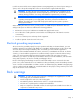
General diagnosis flowchart The General Diagnosis flowchart provides a generic approach to troubleshooting. If you are unsure of the problem, or if the other flowcharts do not correct the problem, use the following flowchart. Item See 1 "Symptom information (on page 25)" 2 "Loose connections (on page 22)" 3 "Service notifications (on page 22)" 4 The most recent version of a particular server or option firmware is available on the following websites: • • HP Support website (http://www.hp.
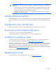
Power-on problems flowchart Symptoms: • The server does not power on. • The system power LED is off or amber. NOTE: For the location of server LEDs and information on their statuses, refer to the server documentation.
Possible causes: • Improperly seated or faulty power supply • Loose or faulty power cord • Power source problem • Power on circuit problem • Improperly seated component or interlock problem • Faulty internal component Item See 1 Server maintenance and service guide, located on the Support CD or the HP website (http://www.hp.
POST problems flowchart Symptoms: • Server does not complete POST NOTE: The server has completed POST when the system attempts to access the boot device.
Item See 1 Server maintenance and service guide, located on the Support CD or the HP website (http://www.hp.com/products/servers/platforms) 2 "Loose connections (on page 22)" 3 "General memory problems are occurring (on page 41)" 4 • • "Hardware problems (on page 35)" Server maintenance and service guide, located on the Support CD or the HP website (http://www.hp.
OS boot problems flowchart Symptom: Server does not boot a previously installed operating system.
Item See 3 "General memory problems are occurring (on page 41)" 4 • • 5 "Hardware problems (on page 35)" Server maintenance and service guide, located on the Support CD or the HP website (http://www.hp.com/products/servers/platforms) "General diagnosis flowchart (on page 27)" Server fault indications flowchart Symptom: Server boots, but the internal health LED or external health LED is red or amber.
NOTE: For the location of server LEDs and information on their statuses, refer to the server documentation. Possible causes: • Improperly seated or faulty internal or external component • Unsupported component installed • Redundancy failure • System overtemperature condition Item See 1 Server maintenance and service guide, located on the Support CD or the HP website (http://www.hp.
Hardware problems The procedures in this section are comprehensive and include steps about or references to hardware features that may not be supported by the server you are troubleshooting.
Power supply problems (on page 36) UPS problems (on page 36) Power source problems Action: 1. Press the Power On/Standby button to be sure it is on. If the server has a Power On/Standby button that returns to its original position after being pressed, be sure you press the switch firmly. 2. Plug another device into the grounded power outlet to be sure the outlet works. Also, be sure the power source meets applicable standards. 3.
7. Check the UPS LEDs to be sure a battery or site wiring problem has not occurred. See the UPS documentation. 8. If the UPS sleep mode is initiated, disable sleep mode for proper operation. The UPS sleep mode can be turned off through the configuration mode on the front panel. 9. Change the battery to be sure damage was not caused by excessive heat, particularly if a recent air conditioning outage has occurred. NOTE: The optimal operating temperature for UPS batteries is 25°C (77°F).
o Connection of the data cable, but not the power cable, of a new device 4. Be sure no memory, I/O, or interrupt conflicts exist. 5. Be sure no loose connections (on page 22) exist. 6. Be sure all cables are connected to the correct locations and are the correct lengths. For more information, refer to the server documentation. 7. Be sure other components were not unseated accidentally during the installation of the new hardware component. 8.
Third-party device problems Action: 1. Refer to the server and operating system documentation to be sure the server and operating system support the device. 2. Be sure the latest device drivers are installed. 3. Refer to the device documentation to be sure the device is properly installed. For example, a thirdparty PCI or PCI-X board may be required to be installed on the primary PCI or PCI-X bus, respectively. Testing the device Action: 1. Uninstall the device.
c. Replace the access panels, and then attempt to restart the server. 2. Be sure the fan configuration meets the functional requirements of the server. Refer to the server documentation. 3. Be sure no ventilation problems exist. If you have been operating the server for an extended period of time with the access panel removed, airflow may have been impeded, causing thermal damage to components. Refer to the server documentation for further requirements. 4.
No hard drives are recognized Action: Be sure no power problems (on page 35) exist. A new hard drive is not recognized Action: 1. Be sure the drive is supported. To determine drive support, see the server documentation or the HP website (http://www.docs.hp.com). 2. Be sure the drive bay is not defective by installing the hard drive in another bay. 3. Run HP Insight Diagnostics (on page 20). Then, replace failed components as indicated. 4.
3. Be sure the memory modules are seated properly. 4. Be sure no operating system errors are indicated. 5. Restart the server and check to see if the error message is still displayed. 6. Run HP Insight Diagnostics (on page 20). Then, replace failed components as indicated. Server fails to recognize existing memory Action: 1. Reseat the memory. Use care when handling DIMMs. 2. Be sure the memory is configured properly. See the server documentation. 3.
a. Remove all but one processor from the server. Replace each with a processor terminator board or blank, if applicable to the server. b. If the server includes PPMs that are not integrated on the system board, remove all PPMs from the server except for the PPM associated with the remaining processor. c. Replace the remaining processor with a known functional processor. If the problem is resolved after you restart the server, a fault exists with one or more of the original processors.
5. Press any key, or type the password, and wait a few moments for the screen to activate to be sure the energy saver feature is not in effect. 6. Be sure the video driver is current. Refer to the third-party video adapter documentation for driver requirements. 7. Be sure a video expansion board has not been added to replace onboard video, making it seem like the video is not working. Disconnect the video cable from the onboard video, and then reconnect it to the video jack on the expansion board.
Printer output is garbled Action: Be sure the correct printer drivers are installed. Network controller problems Network controller is installed but not working Action: 1. Check the network controller LEDs to see if any statuses indicate the source of the problem. For LED information, refer to the network controller documentation. 2. Be sure no loose connections (on page 22) exist. 3. Be sure the network cable is working by replacing it with a known functional cable. 4.
3. Be sure the new expansion board has not changed the server configuration, requiring reinstallation of the network driver. a. Uninstall the network controller driver for the malfunctioning controller in the operating system. b. Restart the server, run BIOS Setup Utility, and be sure the server recognizes the controller and resources are available for the controller. c. Restart the server, and then reinstall the network driver. 4.
Contacting HP Contacting HP technical support or an authorized reseller Before contacting HP, always attempt to resolve problems by completing the procedures in this guide. IMPORTANT: Collect the appropriate server information ("Server information you need" on page 47) and operating system information ("Operating system information you need" on page 48) before contacting HP for support. For the name of the nearest HP authorized reseller: • See the Contact HP worldwide (in English) webpage (http://welcome.
• Any notes describing the details of the problem, including recent changes to the system, the events that triggered or are associated with the problem, and the steps needed to reproduce the problem. • Notes on anything nonstandard about the server setup. • Operating system information ("Operating system information you need" on page 48) Operating system information you need Depending on the problem, you may be asked for certain pieces of information.
• • o lspci -v o uname -a o cat /proc/meminfo o cat /proc/cpuinfo o rpm -ga o dmesg o lsmod o ps -ef o ifconfig -a o chkconfig -list o mount Contents of the following files: o /var/log/messages o /etc/modules.conf or etc/conf.modules o /etc/lilo.conf or /etc/grub.conf o /etc/fstab If HP drivers are installed: o Version of the PSP used o List of drivers from the PSP (/var/log/hppldu.
Refer to "Server software and configuration utilities ("Software and configuration utilities" on page 16)" for more information. Operating system problems Operating system locks up Action: Scan for viruses with an updated virus scan utility. Errors are displayed in the error log Action: Follow the information provided in the error log, and then refer to the operating system documentation.
3. Be sure the server ROM is current and the configuration is correct. 4. Be sure you have printed records of all troubleshooting information you have collected to this point. 5. Be sure you have two good backups before you start. Test the backups using a backup utility. 6. Check the operating system and application software resources to be sure you have the latest information. 7.
• Check system settings to determine if they are the cause of the error. You may need to obtain the settings from the server setup utility and manually set the software switches. Refer to the application documentation, the vendor website, or both. • Check for overwritten files. Refer to the application documentation to find out which files are added by the application. • Reinstall the application. • Be sure you have the most current drivers.
The ROMPaq utility checks the system and provides a choice (if more than one exists) of available firmware revisions. For more information, see the Download drivers and software page for the server. To access the serverspecific page, enter the following web address into the browser: http://www.hp.com/support/ For example: http://www.hp.com/support/dl360g6 To flash the ROM using ROMPaq: 1. Download the system ROMPaq utility diskette or USB drive key for each target server.
Battery replacement If the server no longer automatically displays the correct date and time, you may need to replace the battery that provides power to the real-time clock. Under normal use, battery life is 5 to 10 years. WARNING: The computer contains an internal lithium manganese dioxide, a vanadium pentoxide, or an alkaline battery pack. A risk of fire and burns exists if the battery pack is not properly handled. To reduce the risk of personal injury: • Do not attempt to recharge the battery.
5. Remove the battery. To replace the component, reverse the removal procedure. For more information about battery replacement or proper disposal, contact an authorized reseller or an authorized service provider.
Regulatory compliance notices Regulatory compliance identification numbers For the purpose of regulatory compliance certifications and identification, this product has been assigned a unique regulatory model number. The regulatory model number can be found on the product nameplate label, along with all required approval markings and information. When requesting compliance information for this product, always refer to this regulatory model number.
to radio communications. However, there is no guarantee that interference will not occur in a particular installation. If this equipment does cause harmful interference to radio or television reception, which can be determined by turning the equipment off and on, the user is encouraged to try to correct the interference by one or more of the following measures: • Reorient or relocate the receiving antenna. • Increase the separation between the equipment and receiver.
Canadian notice (Avis Canadien) Class A equipment This Class A digital apparatus meets all requirements of the Canadian Interference-Causing Equipment Regulations. Cet appareil numérique de la classe A respecte toutes les exigences du Règlement sur le matériel brouilleur du Canada. Class B equipment This Class B digital apparatus meets all requirements of the Canadian Interference-Causing Equipment Regulations.
Disposal of waste equipment by users in private households in the European Union This symbol on the product or on its packaging indicates that this product must not be disposed of with your other household waste. Instead, it is your responsibility to dispose of your waste equipment by handing it over to a designated collection point for the recycling of waste electrical and electronic equipment.
Korean notice Class A equipment Class B equipment Chinese notice Class A equipment Laser compliance This product may be provided with an optical storage device (that is, CD or DVD drive) and/or fiber optic transceiver. Each of these devices contains a laser that is classified as a Class 1 Laser Product in accordance with US FDA regulations and the IEC 60825-1. The product does not emit hazardous laser radiation. Each laser product complies with 21 CFR 1040.10 and 1040.
WARNING: The computer contains an internal lithium manganese dioxide, a vanadium pentoxide, or an alkaline battery pack. A risk of fire and burns exists if the battery pack is not properly handled. To reduce the risk of personal injury: • Do not attempt to recharge the battery. • Do not expose the battery to temperatures higher than 60°C (140°F). • Do not disassemble, crush, puncture, short external contacts, or dispose of in fire or water.
Electrostatic discharge Preventing electrostatic discharge To prevent damaging the system, be aware of the precautions you need to follow when setting up the system or handling parts. A discharge of static electricity from a finger or other conductor may damage system boards or other static-sensitive devices. This type of damage may reduce the life expectancy of the device. To prevent electrostatic damage: • Avoid hand contact by transporting and storing products in static-safe containers.
Technical support Before you contact HP Be sure to have the following information available before you call HP: • Technical support registration number (if applicable) • Product serial number • Product model name and number • Product identification number • Applicable error messages • Add-on boards or hardware • Third-party hardware or software • Operating system type and revision level HP contact information For the name of the nearest HP authorized reseller: • See the Contact HP worldwi
• Optional—Parts for which customer self repair is optional. These parts are also designed for customer self repair. If, however, you require that HP replace them for you, there may or may not be additional charges, depending on the type of warranty service designated for your product. NOTE: Some HP parts are not designed for customer self repair. In order to satisfy the customer warranty, HP requires that an authorized service provider replace the part.
Pour plus d'informations sur le programme CSR de HP, contactez votre Mainteneur Agrée local. Pour plus d'informations sur ce programme en Amérique du Nord, consultez le site Web HP (http://www.hp.com/go/selfrepair). Riparazione da parte del cliente Per abbreviare i tempi di riparazione e garantire una maggiore flessibilità nella sostituzione di parti difettose, i prodotti HP sono realizzati con numerosi componenti che possono essere riparati direttamente dal cliente (CSR, Customer Self Repair).
HINWEIS: Einige Teile sind nicht für Customer Self Repair ausgelegt. Um den Garantieanspruch des Kunden zu erfüllen, muss das Teil von einem HP Servicepartner ersetzt werden. Im illustrierten Teilekatalog sind diese Teile mit „No“ bzw. „Nein“ gekennzeichnet. CSR-Teile werden abhängig von der Verfügbarkeit und vom Lieferziel am folgenden Geschäftstag geliefert. Für bestimmte Standorte ist eine Lieferung am selben Tag oder innerhalb von vier Stunden gegen einen Aufpreis verfügbar.
el caso de todas sustituciones que lleve a cabo el cliente, HP se hará cargo de todos los gastos de envío y devolución de componentes y escogerá la empresa de transporte que se utilice para dicho servicio. Para obtener más información acerca del programa de Reparaciones del propio cliente de HP, póngase en contacto con su proveedor de servicios local. Si está interesado en el programa para Norteamérica, visite la página web de HP siguiente (http://www.hp.com/go/selfrepair).
Opcional – Peças cujo reparo feito pelo cliente é opcional. Essas peças também são projetadas para o reparo feito pelo cliente. No entanto, se desejar que a HP as substitua, pode haver ou não a cobrança de taxa adicional, dependendo do tipo de serviço de garantia destinado ao produto. OBSERVAÇÃO: Algumas peças da HP não são projetadas para o reparo feito pelo cliente. A fim de cumprir a garantia do cliente, a HP exige que um técnico autorizado substitua a peça.
Technical support 69
Technical support 70
Acronyms and abbreviations ACU Array Configuration Utility ADU Array Diagnostics Utility BMC baseboard management controller CS cable select DIMM dual inline memory module DU driver update ESD electrostatic discharge IDE integrated device electronics IEC International Electrotechnical Commission IML Integrated Management Log IRQ interrupt request KVM keyboard, video, and mouse Acronyms and abbreviations 71
NEMA National Electrical Manufacturers Association NFPA National Fire Protection Association NVRAM non-volatile memory PCI peripheral component interface PCI Express Peripheral Component Interconnect Express PCI-X peripheral component interconnect extended PDU power distribution unit POST Power-On Self Test PPM processor power module PSP ProLiant Support Pack RBSU ROM-Based Setup Utility ROM read-only memory SCSI small computer system interface SIM Systems Insight Manager Acronyms and abbrevia
TMRA recommended ambient operating temperature TPM trusted platform module UPS uninterruptible power system USB universal serial bus VGA video graphics array Acronyms and abbreviations 73
Index A access panel 6 acoustics statement for Germany 61 airflow requirements 7, 8 application software problems 51 Array Configuration Utility (ACU) 18 Array Diagnostic Utility (ADU) 21 audio 44 audio problems 44 authorized reseller 47, 63 auto-configuration process 17 B backup, restoring 50 batteries, insufficient warning when low 37 batteries, replacing 54, 60 battery 37, 54, 60 battery replacement notice 60 BIOS Serial Console 18 boot options 17 BSMI notice 59 C diagnostic steps 25 diagnostic tools
Insight Diagnostics 20 installation, server options 10, 11 Integrated Management Log (IML) 20 J Japanese notice 59 K Korean notices 60 KVM 44 L laser compliance 60 laser devices 60 LEDs 37 LEDs, troubleshooting 22, 25 Lights-Out 100i Remote Management 21 Linux 48, 51 loose connections 22 M memory 11 memory count error 41, 42 memory not recognized 42 memory problems 41 Microsoft operating systems 48 monitor 44 N network controllers 45 O operating system crash 50 operating system problems 50 operating s
software problems 49 software troubleshooting 51 space requirements 7 static electricity 62 StorageWorks Library and Tape Tools (L&TT) 20 support 63 switches 15 symbols on equipment 23 symptom information 25 system board battery 60 Systems Insight Manager 20 T Taiwan battery recycling notice 61 technical support 47, 63 telephone numbers 47, 63 temperature requirements 8 third-party devices 39 troubleshooting 22 troubleshooting sequence 25 Trusted Platform Module (TPM) 12, 13, 14 U unknown problem 38 updat