
Instruction Manual


Table Of Contents
- HP ProLiant SB460c SAN Gateway Storage Server
- Table of Contents
- About this guide
- 1 Storage management overview
- 2 File server management
- File services features in Windows Storage Server 2003 R2
- File services management
- Volume shadow copies
- Folder and share management
- File Server Resource Manager
- Other Windows disk and data management tools
- Additional information and references for file services
- 3 Print services
- 4 Microsoft Services for Network File System (MSNFS)
- MSNFS Features
- MSNFS use scenarios
- MSNFS components
- Administering MSNFS
- Server for NFS
- User Name Mapping
- Microsoft Services for NFS troubleshooting
- Microsoft Services for NFS command-line tools
- Optimizing Server for NFS performance
- Print services for UNIX
- MSNFS components
- 5 Other network file and print services
- 6 Enterprise storage servers
- 7 Cluster administration
- Cluster overview
- Cluster terms and components
- Cluster concepts
- Cluster planning
- Preparing for cluster installation
- Cluster installation
- Configuring cluster service software
- Cluster groups and resources, including file shares
- Print services in a cluster
- Advanced cluster administration procedures
- Additional information and references for cluster services
- 8 Troubleshooting, servicing, and maintenance
- 9 System recovery
- A Regulatory compliance and safety
- Index
• Storing the most current version of the cluster database
• Guaranteeing that only one set of active communicating nodes is allowed to operate as a cluster
Cluster concepts
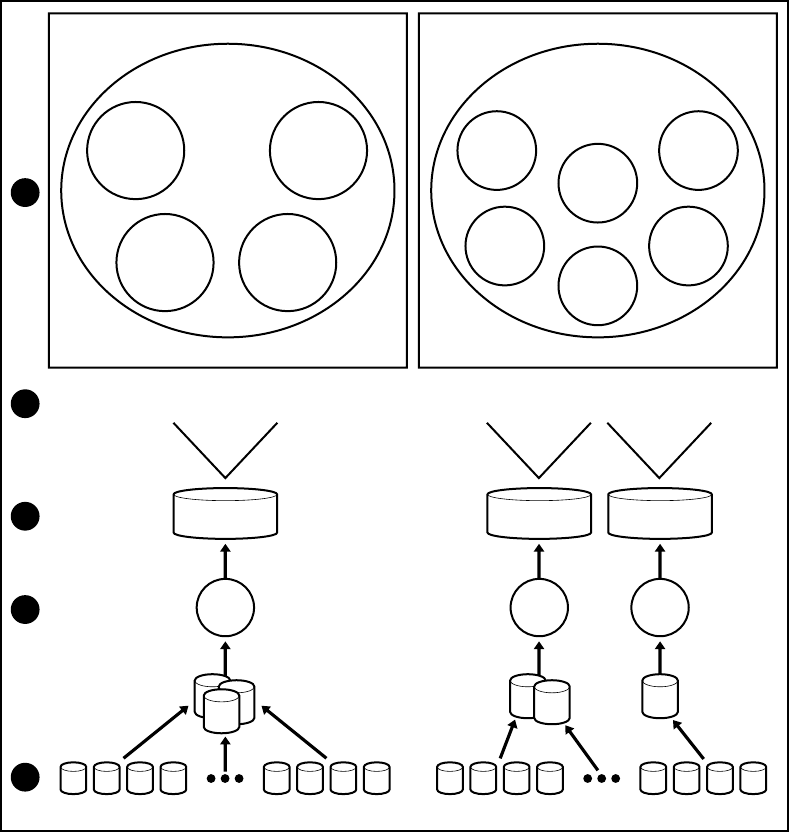
Figure 26 illustrates a typical cluster configuration with the corresponding storage elements. The
diagram progresses from the physical disks to the file shares, showing the relationship between both
the cluster elements and the physical devices underlying them. While the diagram only illustrates two
nodes, the same concepts apply for multi-node deployments.
Cluster
Resource:
Disk E
Cluster
Resource:
File Share
Eng1
E:\eng1
Cluster
Resource:
Network
Name
Fileserver1
Cluster
Resource:
IP Address
172.18.1.99
Cluster Group
FS1Eng
Node 1
Cluster
Resource:
Disk F
Cluster
Resource:
File Share
Mar1
F:\Mar1
Cluster
Resource:
File Share
Mar4
G:\Mar4
Cluster
Resource:
Network
Name
Fileserver2
Cluster
Resource:
IP Address
172.18.1.98
Cluster
Resource:
Disk G
Cluster Group
FS1Market
Node 2
E:\eng1
E:\eng2
E:\eng3
F:\Mar1
F:\Mar2
F:\Mar3
Raidsets 1-3 Raidsets 4-5 Raidsets 6
G:\Mar4
G:\Mar5
G:\Mar6
Cluster Resource
Physical Disk E
Cluster Resource
Physical Disk F
Cluster Resource
Physical Disk G
Basic
Disk E:
Basic
Disk F:
Basic
Disk G:
Physical Disks 1-4 Physical Disks 9-12 Physical Disks 13-16 Physical Disks 20-23
1
4
2
3
5
Figure 26 Cluster concepts diagram
Sequence of events for cluster resources
The sequence of events in the diagram includes:
1. Physical disks are combined into RAID arrays and LUNs.
2. LUNS are designated as basic disks, formatted, and assigned a drive letter via Disk Manager.
Cluster administration92