HP ProLiant ML570 Generation 4 Server User Guide March 2006 (First Edition) Part Number 406862-001
© Copyright 2006 Hewlett-Packard Development Company, L.P. The information contained herein is subject to change without notice. The only warranties for HP products and services are set forth in the express warranty statements accompanying such products and services. Nothing herein should be construed as constituting an additional warranty. HP shall not be liable for technical or editorial errors or omissions contained herein. Microsoft and Windows are U.S. registered trademarks of Microsoft Corporation.
Contents Component identification ............................................................................................................... 7 Front panel components ............................................................................................................................. 7 Front panel LEDs and buttons ...................................................................................................................... 8 Rear panel components..........................................
Configuring the memory ................................................................................................................. 53 Hot-plug SAS and SATA hard drive option ................................................................................................. 54 Installing a hot-plug SAS or SATA hard drive .................................................................................... 55 Removing a hot-plug SAS hard drive ...............................................................
HP Instant Support Enterprise Edition................................................................................................ 84 Keeping the system current ....................................................................................................................... 85 Drivers ......................................................................................................................................... 85 ProLiant Support Packs .....................................................
Technical support...................................................................................................................... 112 Before you contact HP............................................................................................................................ 112 HP contact information ........................................................................................................................... 112 Customer self repair...................................................
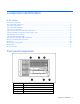
Component identification In this section Front panel components ............................................................................................................................ 7 Front panel LEDs and buttons ..................................................................................................................... 8 Rear panel components.............................................................................................................................
Item Description 5 Tape drive blank 6 SAS hard drives Front panel LEDs and buttons Item Description Status 1 UID button and LED Blue = Activated Flashing blue = System being managed remotely Off = Deactivated 2 Internal health LED Green = Normal (system on) Flashing amber = System health degraded Flashing red = System health critical 3 External health (power supply) LED Green = Normal (system on) Flashing amber = Redundant power supply failure Flashing red = Power supply failure.
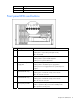
Rear panel components Item Description 1 NIC 1 connector 2 NIC 2 connector 3 USB connectors 4 iLO 2 connector 5 Parallel connector 6 PCI-X slot 1, 64-bit/100-MHz 7 PCI-X slot 2, 64-bit/100-MHz 8 PCI-X slot 3, 64-bit/100-MHz 9 PCI-X slot 4, 64-bit/100-MHz 10 PCI Express x4 slot 5 11 PCI Express x4 slot 6 12 PCI Express x4 slot 7 13 PCI Express x4 slot 8 14 PCI Express x4 slot 9 15 PCI Express x4 slot 10 16 Power supply (primary) 17 Power supply blank 18 T-15 Torx screwdr
Rear panel LEDs and buttons Item Description Status 1 UID LED Blue = Activated Flashing blue = System remotely managed Off = Deactivated 2 3 4 NIC activity LED (Integrated NC371i) Green or flashing green = Network activity NIC link LED (Integrated NC371i) Green = Linked to network iLO 2 NIC activity LED Green or flashing green = Network activity Off = No network activity Off = Not linked to network Off = No network activity 5 iLO 2 NIC link LED Green = Linked to network Off = Not linked to
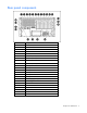
System board components Item Description 1 PCI Express x4 slot 10 2 PCI Express x4 slot 9 3 PCI Express x4 slot 8 4 PCI Express x4 slot 7 5 PCI Express x4 slot 6 6 PCI Express x4 slot 5 7 PCI-X slot 4, 64-bit/100-MHz 8 PCI-X slot 3, 64-bit/100-MHz 9 PCI-X slot 2, 64-bit/100-MHz 10 PCI-X slot 1, 64-bit/100-MHz 11 Memory board slot 1 12 Memory board slot 2 13 Front video/USB connector 14 Memory board slot 3 15 Memory board slot 4 16 PPM slot 1 17 PPM slot 2 18 Systems Ins
Item Description 26 Processor socket 2 27 Fan board signal connector 28 Fan board power connector 29 Processor socket 1 30 Power connector 31 Internal USB connector 32 Fan connector 33 Fan connector 34 Power supply signal connector System maintenance switches The system maintenance switch (SW1) is an eight-position switch that is reserved. The default position for all eight positions is Off.
NMI switch The NMI switch allows administrators to perform a memory dump before performing a hard reset. Crash dump analysis is an essential part of eliminating reliability problems, such as hangs or crashes in operating systems, device drivers, and applications. Many crashes freeze a system, requiring you to do a hard reset. Resetting the system erases any information that would support root cause analysis.
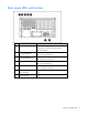
System board LEDs and Systems Insight Display codes In normal operations, all the LEDs are off unless one of the components fails. When a component fails, the LED illuminates amber. The Systems Insight Display codes provide more specific information for troubleshooting the server. The codes are shown in the following table.
Code Component Status A0 Pre POST code Standby mode P5 Power supply No power from the power supply _5 Power backplane No 5-V power from the power supply backplane board 33 Power backplane No 3.3-V power from the power supply backplane board 15 1.5-V regulator No 1.
SAS and SATA hard drive LEDs Item Description 1 Fault/ID LED (amber/blue) 2 Online LED (green) SAS and SATA hard drive LED combinations Online/Activity LED (green) Fault/UID LED (amber/blue) Interpretation On, off, or flashing Alternating amber and blue The drive has failed, or a predictive failure alert has been received for this drive; it also has been selected by a management application.
Online/Activity LED (green) Fault/UID LED (amber/blue) Interpretation Off Steadily amber A critical fault condition has been identified for this drive, and the controller has placed it offline. Replace the drive as soon as possible. Off Amber, flashing regularly (1 Hz) A predictive failure alert has been received for this drive. Replace the drive as soon as possible. Off Off The drive is offline, a spare, or not configured as part of an array.
Item Description Status 3 Locking switch — 4 Removable Green = OK to remove the board Off = Do not remove if the system is on 5 DIMM 1 LED Green = DIMM installed Amber = Failed or degraded DIMM Flashing amber = DIMM configuration error Off = No DIMM installed 6 DIMM 2 LED Green = DIMM installed Amber = Failed or degraded DIMM Flashing amber = DIMM configuration error Off = No DIMM installed 7 DIMM 3 LED Green = DIMM installed Amber = Failed or degraded DIMM Flashing amber = DIMM configurati
Item Description Status 14 Board status LED Off = Power off - memory board locking switch not engaged or invalid memory configuration. Green = Normal operation Flashing green = Board is rebuilding Flashing amber = DIMM on this board encountered memory errors Flashing amber = one of the following conditions: • Unlocking a memory board that should not be removed • Attempting to insert a memory board at runtime that fails *The following applies to an invalid AMP error.
DIMM slots Item Description 1 DIMM slot 1, PC2-3200R 2 DIMM slot 2, PC2-3200R 3 DIMM slot 3, PC2-3200R 4 DIMM slot 4, PC2-3200R 5 DIMM slot 5, PC2-3200R 6 DIMM slot 6, PC2-3200R Hot-plug power supply LEDs Item Description 1 Power LED (primary power supply) Component identification 20
Item Description 2 Failure LED (primary power supply) 3 Power LED (redundant power supply) 4 Failure LED (redundant power supply) Power LED (green) Failure LED (amber) Status Off Off No AC power to all power supply units Off On No AC power to this power supply unit only or power supply failure (includes over voltage and over temperature) Flashing Off AC present/Standby outputs on On Off Power supply DC outputs On and OK Off Flashing Power supply failure (current limit) Hot-plug fan
Hot-plug fan LEDs Status Green = Operating normally Amber = Failed Off = No power Component identification 22
Operations In this section Power up the server ................................................................................................................................ 23 Power down the server............................................................................................................................ 23 Extend the server from the rack ................................................................................................................ 23 Unlock and remove the tower bezel...
2. Extend the server on the rack rails until the server rail-release latches engage. NOTE: The release latches will lock into place when the rails are fully extended. WARNING: To reduce the risk of personal injury or equipment damage, be sure that the rack is adequately stabilized before extending a component from the rack. WARNING: To reduce the risk of personal injury, be careful when pressing the server rail-release latches and sliding the server into the rack.
Unlock and remove the tower bezel Tower servers have a bezel that must be unlocked and opened before accessing the hard drive cage, diskette drive, DVD drive, and the Power On/Standby button. In addition, the bezel is also removable when converting a tower server to a rack server. 1. Turn the key (provided with the server) counterclockwise to unlock the bezel. 2. Open the bezel.
3. Remove the tower bezel if necessary. Remove the rack bezel The rack bezel must remain installed during normal server operations. The rack bezel remains installed for all hardware options installations, except for the following situations: • Removing or replacing a SAS hard drive cage • Converting the server from a rack model to a tower model To remove the rack bezel: 1. Extend or remove the server from the rack ("Extend the server from the rack" on page 23). 2.
5. Pull the rack bezel away from the chassis. Remove the access panel WARNING: To reduce the risk of personal injury from hot surfaces, allow the drives and the internal system components to cool before touching them. CAUTION: Do not operate the server for long periods with the access panel open or removed. Operating the server in this manner results in improper airflow and improper cooling that can lead to thermal damage. 1.
Setup In this section Optional installation services ................................................................................................................... 28 Rack planning resources ......................................................................................................................... 29 Optimum environment............................................................................................................................. 29 Rack warnings and cautions ................
For more information on Care Packs, refer to the HP website (http://www.hp.com/hps/carepack/servers/cp_proliant.html). Rack planning resources The rack resource kit ships with all HP branded or Compaq branded 9000, 10000, and H9 series racks. For more information on the content of each resource, refer to the rack resource kit documentation. If you intend to deploy and configure multiple servers in a single rack, refer to the white paper on highdensity deployment at the HP website (http://www.hp.
CAUTION: If a third-party rack is used, observe the following additional requirements to ensure adequate airflow and to prevent damage to the equipment: • Front and rear doors—If the 42U rack includes closing front and rear doors, you must allow 5,350 sq cm (830 sq in) of holes evenly distributed from top to bottom to permit adequate airflow (equivalent to the required 64 percent open area for ventilation).
Furthermore, you must be sure that all power distribution devices used in the installation, such as branch wiring and receptacles, are listed or certified grounding-type devices. Because of the high ground-leakage currents associated with multiple servers connected to the same power source, HP recommends the use of a PDU that is either permanently wired to the building’s branch circuit or includes a nondetachable cord that is wired to an industrial-style plug.
CAUTION: Do not operate the server for long periods with the access panel open or removed. Operating the server in this manner results in improper airflow and improper cooling that can lead to thermal damage. Identifying tower server shipping carton contents Unpack the server shipping carton and locate the materials and documentation necessary for installing the server.
Setting up a tower server Follow these steps to set up a tower model server. If you are going to install the server into a rack, refer to the rack installation section ("Installing the server into the rack" on page 34). 1. Connect peripheral devices to the server. WARNING: To reduce the risk of electric shock, fire, or damage to the equipment, do not plug telephone or telecommunications connectors into RJ-45 connectors.
Item Description 21 Mouse connector 22 Video connector 23 Serial connector 2. Connect the power cord to the power supply. 3. Open the power cord retaining clip and thread the power cord through the retaining clip. 4. Snap the tab into place to secure the power cord. 5. Connect the power cord to the AC power source. WARNING: To reduce the risk of electric shock or damage to the equipment: • Do not disable the power cord grounding plug. The grounding plug is an important safety feature.
WARNING: To reduce the risk of electric shock, fire, or damage to the equipment, do not plug telephone or telecommunications connectors into RJ-45 connectors.
4. Snap the tab into place to secure the power cord. 5. Connect the power cord to the AC power source. WARNING: To reduce the risk of electric shock or damage to the equipment: • Do not disable the power cord grounding plug. The grounding plug is an important safety feature. • Plug the power cord into a grounded (earthed) electrical outlet that is easily accessible at all times. • Unplug the power cord from the power supply to disconnect power to the equipment.
• SmartStart assisted installation—Insert the SmartStart CD into the CD-ROM drive and reboot the server. • Manual installation—Insert the operating system CD into the CD-ROM drive and reboot the server. This process may require you to obtain additional drivers from the HP website (http://www.hp.com/support). Follow the on-screen instructions to begin the installation process.
Hardware options installation In this section Processor option..................................................................................................................................... 38 Memory options ..................................................................................................................................... 43 Hot-plug SAS and SATA hard drive option ................................................................................................ 54 Drive options .......
4. Remove the processor air baffle. 5. Unlock the processor retaining bracket. 6. Open the processor retaining bracket. 7. Open the processor locking lever.
CAUTION: Failure to completely open the processor locking lever prevents the processor from seating during installation, leading to hardware damage. 8. Align the processor assembly with the socket. IMPORTANT: Determine the correct processor orientation by observing the guide pins on the base of the processor retaining bracket and the three corresponding guide slots on the processor assembly. 9. Install the processor assembly and close the processor locking lever.
NOTE: Your heatsink may appear different than shown. 10. Close and lock the processor retaining bracket.
11. Release and remove the PPM hold-down. 12. Install the PPM. IMPORTANT: Always install a PPM when you install a processor. The system fails to boot if the corresponding PPM is missing. NOTE: The appearance of compatible PPMs may vary. 13. Install the PPM retaining bracket. 14. Install the processor air baffle. 15. Install the access panel (on page 27). 16. Do one of the following: — Install and lock the bezel. — Slide the server back into the rack.
Memory options This server supports up to four memory boards. Each memory board contains six DIMM slots for a total of 24 DIMM slots in the server. Memory can be expanded by installing PC2-3200R Registered DDR2 DRAM DIMMs.
• The system can be configured for any AMP mode in RBSU. RBSU displays a warning message if the selected AMP mode is not supported by the current configuration. However, if the DIMM configuration at POST does not meet the requirements for the AMP mode selected in RBSU, the server defaults to Advanced ECC. The system indicates this by displaying a message during POST and the status LED for the configured AMP mode flashes amber.
• • If multiple hot-add operations are performed, allow one board insertion operation to complete (as indicated by the memory board LEDs and OS logs) before inserting another memory board. If a memory board (which contains DIMMs) is unlocked while in Advanced ECC mode, audio alarms and visual alerts occur. CAUTION: When the memory board locking switch is unlocked in a mode that does not support hot-add or hot-replace capabilities, audio alarms and visual alerts occur.
After installing DIMMs, use RBSU to configure the system for online spare memory support. Hot-plug mirrored memory Hot-Plug mirrored memory (mirrored memory) provides a higher level of memory protection than either Advanced ECC or Online Spare Memory. With mirrored memory, the server is protected against uncorrectable memory errors that would otherwise result in server failure. Mirrored memory allows the server to keep two copies of all memory data on separate memory boards.
Hot-plug RAID memory Hot-plug RAID memory (RAID memory) provides a similar level of memory protection as mirrored memory but obtains this protection using less total memory. For example, in a RAID memory configuration, 25% of the installed memory is not available to the OS. In a mirrored memory configuration, however, 50% of the installed memory is not available to the OS. RAID memory protects the server against uncorrectable memory errors that would otherwise result in a server failure.
Advanced Memory Protection Mode Hot-Replace Supported Advanced ECC Hot-Add Supported X Online Spare Memory Hot-Plug Mirrored Memory X Hot-Plug RAID Memory X When the server is configured for mirrored or RAID memory, you can perform a hot-replacement procedure in the following manner without powering down the server or experiencing server downtime: 1. Remove a memory board. 2. Replace failed or degraded DIMM(s). 3. Reinstall the memory board in the slot from which it was removed.
4. Unlock the memory board locking switch. CAUTION: Do not attempt to unlock the memory board in an operational server when the board removal LED is not green. This generates an audio alarm and causes the memory board LEDs to flash amber. Proceeding to remove the memory board causes server failure. CAUTION: To prevent server failure during a hot-plug removal procedure, do not remove the memory board from the server until the board status LED stops flashing. 5.
• Install a DIMM. 8. Align the memory board with the memory slot and memory board guide clips. 9. Install the memory board and close the ejector lever. 10. Move the locking switch to the locked position. NOTE: In hot-plug procedures, all LEDs now turn off except the board status LED, which flashes green while the board is rebuilding. This process may take several minutes. 11.
Removing and installing a memory board (non-hot-plug) NOTE: The ProLiant ML570 G3/G4 memory board operates at different front-side bus speeds: • In HP ProLiant ML570 Generation 4 Servers, the G3/G4 memory board operates at 667 MHz or 800 MHz, depending on the front-side bus speed of the installed processor. • In HP ProLiant ML570 Generation 3 Servers, the G3/G4 memory board operates at 667 MHz with no performance gain over ProLiant ML570 G3 memory boards.
9. • Remove a DIMM. • Install a DIMM. Align the memory board with the memory slot and the memory board guide clips. 10. Install the memory board into the server and close the ejector lever.
11. Move the locking switch to the locked position. 12. Configure the memory ("Configuring the memory" on page 53). 13. Install the access panel (on page 27). 14. Do one of the following: — Install and lock the bezel. — Slide the server back into the rack. Configuring the memory Configuring the memory system of the server requires configuring both hardware and software. To configure the memory: 1. Install the correct amount of memory for the desired AMP mode.
7. Once the memory has been tested, re-enable POST Speed Up for faster system boot, if desired. ROM-based diagnostics 1. Power on the server ("Power up the server" on page 23). 2. Press the F10 key, when prompted, to enter the System Maintenance menu. 3. Select Diagnostics. 4. Run the Memory Diagnostics. 5. Once the memory has been tested, exit the utility and reboot. 6. Select the AMP mode ("Selecting the AMP mode" on page 54). Selecting the AMP mode 1.
Installing a hot-plug SAS or SATA hard drive 1. Remove the SAS or SATA hard drive blank. 2. Prepare the hard drive.
3. Install the hard drive. 4. Determine the status of the hard drive from the hot-plug SAS hard drive LED combinations. Removing a hot-plug SAS hard drive CAUTION: To prevent improper cooling and thermal damage, do not operate the server unless all bays are populated with either a component or a blank. 1. Determine the status of the hard drive from the hot-plug SAS hard drive LED combinations. 2. Back up all server data on the hard drive. 3. Remove the hard drive.
Drive options Optical drives The standard configuration for this server is one DVD drive (in the right drive bay) and one drive blank (in the left drive bay). An optional DVD-ROM or diskette drive may be installed in the left drive bay. A diskette drive cannot be installed in the right drive bay. CAUTION: Always populate each media bay with either a device or a blank. Proper airflow can only be maintained when the bays are populated. Unpopulated drive bays can lead to improper cooling and thermal damage.
Removable media devices A half-height SCSI tape drive or a half-height USB tape drive may be installed in the removable media bay. A half-height CD-ROM, DVD-ROM, CD-R, or DVD-R drive is not supported. Removing the tape drive blank 1. Unlock and open the tower bezel ("Unlock and remove the tower bezel" on page 25) (tower servers only). CAUTION: Always populate each media bay with either a device or a blank. Proper airflow can only be maintained when the bays are populated.
6. Remove the center wall. 7. Remove all memory boards ("Removing and installing a memory board (hot-plug)" on page 48, "Removing and installing a memory board (non-hot-plug)" on page 51). 8. Remove the memory cage. 9. Disconnect all required cables from the system board.
10. Remove the system board. 11. Remove the tape drive blank ("Unlock and remove the tower bezel" on page 25). NOTE: Most devices have holes designed to correspond with the wire retainers that are installed in the upper slot of the guide clips. For devices that have holes designed to correspond to the lower slot of the guide clip, the wire retainer must be removed and reinstalled in the lower slot of the clip. 12.
d. Repeat for the right plastic clip. 14. Connect the power cable from the server to the tape drive. 15. Connect one end of the data cable to the tape drive and thread the other end into the server through the tape drive bay. NOTE: The appropriate cables should ship in the individual option kits or with the device being installed. IMPORTANT: Route the USB cable under the mid fan cage. 16. Slide the tape drive into the bay until it is seated securely. 17.
23. Install the processor air baffle ("Processor option" on page 38). 24. Install the access panel. ("Install the access panel" on page 27) 25. Do one of the following: — Install and lock the bezel. — Slide the server back into the rack. 26. Power up the server (on page 23). Redundant hot-plug power supply option The server supports a second hot-plug power supply to provide redundant power to the system in the event of a failure in the primary power supply.
2. Install the redundant hot-plug power supply. 3. Connect the power cord to the redundant power supply. 4. Secure the power cords to the retaining clip ("Setting up a tower server" on page 33). 5. Connect the power cord to the power source. 6. Be sure that the power supply LED is green. 7. Be sure that the front panel external health LED is green ("Front panel LEDs and buttons" on page 8).
2. Remove the access panel (on page 27). 3. Install fans 1, 3 and 5. NOTE: Any hot-plug fan provided in the redundant hot-plug fan cage option kit can be installed in any of the hot-plug fan slots. Fans are keyed to fit only one way in the slot. 4. Observe the LED on each installed fan to be sure it is green. 5. Observe the internal system health LED on the front panel to be sure it is green ("Front panel LEDs and buttons" on page 8). 6. Install the access panel.
3. Remove the failed hot-plug fan. 4. Install a new hot-plug fan ("Installing hot-plug fans" on page 63). 5. Replace additional fans if needed. 6. Observe the internal system health LED on the front panel and the LEDs on each installed fan to be sure it is green. NOTE: If the front panel internal system health LED is not green after you install hot-plug fans, reseat the hotplug fan or refer to the troubleshooting section. 7. Install the access panel (on page 27). 8.
Slot Expansion card type Capable speed 9 PCI Express x4 10 PCI Express x4 *HP recommends that cards with speeds of at least 100 MHz be installed in these slots. If cards with lower bus speeds are installed, the bus speed will be reduced. However, server performance will not suffer if the speed on one bus is slower than the speed on a different bus. Removing an expansion slot cover 1. Power down the server (on page 23). 2.
5. Open the retaining clip and unlock the PCI slot release lever. 6. Install the expansion board. 7. Lock the PCI slot release lever and close the retaining clip. 8. Connect any required internal or external cables to the expansion board. For additional information, refer to the documentation that ships with the expansion board. 9. Install the access panel (on page 27). 10. Do one of the following: — Install and lock the bezel. — Slide the server back into the rack.
The tower-to-rack conversion kit includes: • Rack rail assemblies • Server rails • Cable management arm bracket • Cable management arm support bracket (screw retaining plate) • Installation screws • Cable management arm • Rack bezel assembly • Tower-to-rack conversion installation instructions document In addition to the items supplied in the conversion kit, use the Torx T-15 screwdriver ("Rear panel components" on page 9). Before proceeding with the tower-to-rack conversion: 1.
2. Remove the three T-15 Torx screws from each of the four casters and remove the casters. Removing the tower cover 1. Remove the two T-15 Torx screws that secure the tower cover to the server. 2. Slide the tower cover toward the rear of the server and pull the cover away from the chassis. 3. Turn the server over so that the access panel is on top. Installing the rack bezel 1. Remove the access panel (on page 27).
2. Remove the front fan cage. 3. Remove the tower bezel retaining clips from the front panel. 4. Remove the media blank. ("Removing the tape drive blank" on page 58) 5. Install the fan cage. 6. Align the three tabs on each side of the rack bezel with the corresponding slots in the chassis. 7. Secure the rack bezel to the server: a. Be sure the latch locks in place on the inside of the media bay.
b. Install six 6-32 Torx T-15 screws (three per side) into the corresponding holes on the rack bezel. 8. Install the server into the rack ("Installing the server into the rack" on page 34). Rack-to-tower conversion The rack-to-tower conversion kit includes all equipment required to convert the rack model server into a tower model server.
Removing the cable management arm Pull the release pin and slide the cable management arm out from the inner rail. Removing the server from the rack WARNING: The server is very heavy, up to 63.5 kg (140 lb). To reduce the risk of personal injury or damage to the equipment: • Remove all power supplies and hard drives to reduce the weight of the server before lifting it. • Observe local occupational health and safety requirements and guidelines for manual material handling.
3. Remove the server from the rack. 4. Place the server on a flat, level surface with the access panel facing down. Removing the server rails 1. Release the latch while pressing the rail against the side of the chassis and slide the rail toward the rear of the server, lining up the keys with the larger keyholes. 2. Remove the rail. 3. Repeat steps 1 and 2 for the other rail. Installing the tower cover 1. Remove the rack bezel (rack servers only) ("Remove the rack bezel" on page 26). 2.
Installing the casters Use a T-15 Torx screwdriver to install the three T-15 Torx screws into each of the four casters. Installing the tower bezel 1. Set the server in its upright tower position. CAUTION: Be sure to lock the casters and have the access panel in place before turning or reorienting the server position. 2. Install the two retention clips on the front of the server. 3. Line up the hinges of the tower bezel with the corresponding slots on the chassis and slide the hinges onto the pins. 4.
7. Connect all cables ("Rear panel components" on page 9). 8. Power up the server (on page 23).
Cabling In this section Storage device cabling guidelines............................................................................................................ 76 Tape drive cabling to the USB connector................................................................................................... 76 SAS cabling .......................................................................................................................................... 77 Video connector cabling .......................
SAS cabling Video connector cabling Cabling 77
Battery-backed write cache cabling Cabling 78
Software and configuration utilities In this section Configuration tools ................................................................................................................................. 79 Management tools.................................................................................................................................. 82 Diagnostic tools .....................................................................................................................................
For more information, and to download the SmartStart Scripting Toolkit, refer to the HP website (http://www.hp.com/servers/sstoolkit).
Array Configuration Utility ACU is a browser-based utility with the following features: • Runs as a local application or remote service • Supports online array capacity expansion, logical drive extension, assignment of online spares, and RAID or stripe size migration • Suggests the optimum configuration for an unconfigured system • Provides different operating modes, enabling faster configuration or greater control over the configuration options • Remains available any time that the server is on •
Management tools Automatic Server Recovery ASR is a feature that causes the system to restart when a catastrophic operating system error occurs, such as a blue screen, ABEND, or panic. A system fail-safe timer, the ASR timer, starts when the System Management driver, also known as the Health Driver, is loaded. When the operating system is functioning properly, the system periodically resets the timer. However, when the operating system fails, the timer expires and restarts the server.
HP Systems Insight Manager HP SIM is a web-based application that allows system administrators to accomplish normal administrative tasks from any remote location, using a web browser. HP SIM provides device management capabilities that consolidate and integrate management data from HP and third-party devices. IMPORTANT: You must install and use HP SIM to benefit from the Pre-Failure Warranty for processors, SCSI hard drives, and memory modules.
Diagnostic tools HP Insight Diagnostics HP Insight Diagnostics is a proactive server management tool, available in both offline and online versions, that provides diagnostics and troubleshooting capabilities to assist IT administrators who verify server installations, troubleshoot problems, and perform repair validation. HP Insight Diagnostics Offline Edition performs various in-depth system and component testing while the OS is not running. To run this utility, launch the SmartStart CD.
For more information on ISEE, refer to the HP website (http://www.hp.com/hps/hardware/hw_enterprise.html). To download HP ISEE, visit the HP website (http://www.hp.com/hps/hardware/hw_downloads.html). For installation information, refer to the HP ISEE Client Installation and Upgrade Guide (ftp://ftp.hp.com/pub/services/hardware/info/isee_client.pdf). Keeping the system current Drivers The server includes new hardware that may not have driver support on all operating system installation media.
Change control and proactive notification HP offers Change Control and Proactive Notification to notify customers 30 to 60 days in advance of upcoming hardware and software changes on HP commercial products. For more information, refer to the HP website (http://h18023.www1.hp.com/solutions/pcsolutions/pcn.html). Natural language search assistant The natural language search assistant (http://www.hp.
Troubleshooting In this section Troubleshooting resources ....................................................................................................................... 87 Pre-diagnostic steps ................................................................................................................................ 87 Loose connections .................................................................................................................................. 90 Service notifications.....
Important safety information Before servicing this product, read the Important Safety Information document provided with the server. Symbols on equipment The following symbols may be placed on equipment to indicate the presence of potentially hazardous conditions. This symbol indicates the presence of hazardous energy circuits or electric shock hazards. Refer all servicing to qualified personnel. WARNING: To reduce the risk of injury from electric shock hazards, do not open this enclosure.
WARNING: To reduce the risk of personal injury or damage to the equipment, be sure that: • The leveling feet are extended to the floor. • The full weight of the rack rests on the leveling feet. • The stabilizing feet are attached to the rack if it is a single-rack installation. • The racks are coupled together in multiple-rack installations. • Only one component is extended at a time. A rack may become unstable if more than one component is extended for any reason.
Prepare the server for diagnosis 1. Be sure the server is in the proper operating environment with adequate power, air conditioning, and humidity control. Refer to the server documentation for required environmental conditions. 2. Record any error messages displayed by the system. 3. Remove all diskettes and CDs from the media drives. 4. Power down the server and peripheral devices if you will be diagnosing the server offline. Always perform an orderly shutdown, if possible. This means you must: a.
Troubleshooting flowcharts To effectively troubleshoot a problem, HP recommends that you start with the first flowchart in this section, "Start diagnosis flowchart (on page 91)," and follow the appropriate diagnostic path. If the other flowcharts do not provide a troubleshooting solution, follow the diagnostic steps in "General diagnosis flowchart (on page 92).
General diagnosis flowchart The General diagnosis flowchart provides a generic approach to troubleshooting. If you are unsure of the problem, or if the other flowcharts do not fix the problem, use the following flowchart.
Item Refer to 4 The most recent version of a particular server or option firmware is available on the following websites: • HP Support website (http://www.hp.com/support) • HP ROM-BIOS/Firmware Updates website (http://h18023.www1.hp.com/support/files/server/us/romflash.ht ml) 5 "General memory problems are occurring" in the HP ProLiant Servers Troubleshooting Guide located on the Documentation CD or on the HP website (http://www.hp.
Server power-on problems flowchart Symptoms: • The server does not power on. • The system power LED is off or amber. • The external health LED is red or amber.
• The internal health LED is red or amber. NOTE: For the location of server LEDs and information on their statuses, refer to the server documentation.
Troubleshooting 96
POST problems flowchart Symptoms: • Server does not complete POST NOTE: The server has completed POST when the system attempts to access the boot device. • Server completes POST with errors Possible problems: • Improperly seated or faulty internal component • Faulty KVM device • Faulty video device Item Refer to 1 "POST error messages and beep codes" 2 "Video problems" in the HP ProLiant Servers Troubleshooting Guide located on the Documentation CD or on the HP website (http://www.hp.
OS boot problems flowchart Symptoms: • Server does not boot a previously installed operating system • Server does not boot SmartStart Possible causes: • Corrupted operating system • Hard drive subsystem problem Troubleshooting 98
Item Refer to 1 HP ROM-Based Setup Utility User Guide (http://www.hp.com/servers/smartstart) 2 "POST problems flowchart (on page 97)" 3 • "Hard drive problems" in the HP ProLiant Servers Troubleshooting Guide located on the Documentation CD or on the HP website (http://www.hp.com/support) • Controller documentation 4 "HP Insight Diagnostics (on page 84)" or in the HP ProLiant Servers Troubleshooting Guide located on the Documentation CD or on the HP website (http://www.hp.
Server fault indications flowchart Symptoms: • Server boots, but a fault event is reported by Insight Management Agents (on page 83) • Server boots, but the internal health LED, external health LED, or component health LED is red or amber NOTE: For the location of server LEDs and information on their statuses, refer to the server documentation.
Possible causes: • Improperly seated or faulty internal or external component • Unsupported component installed • Redundancy failure • System overtemperature condition Item Refer to 1 "Management agents (on page 83)" or in the HP ProLiant Servers Troubleshooting Guide located on the Documentation CD or on the HP website (http://www.hp.
POST error messages and beep codes For a complete listing of error messages, refer to the "POST error messages" in the HP ProLiant Servers Troubleshooting Guide located on the Documentation CD or on the HP website (http://www.hp.com/support). WARNING: To avoid potential problems, ALWAYS read the warnings and cautionary information in the server documentation before removing, replacing, reseating, or modifying system components.
Electrostatic discharge In this section Preventing electrostatic discharge........................................................................................................... 103 Grounding methods to prevent electrostatic discharge .............................................................................. 103 Preventing electrostatic discharge To prevent damaging the system, be aware of the precautions you need to follow when setting up the system or handling parts.
Regulatory compliance notices In this section Regulatory compliance identification numbers.......................................................................................... 104 Federal Communications Commission notice ........................................................................................... 104 Declaration of conformity for products marked with the FCC logo, United States only................................... 105 Modifications......................................................
Class A equipment This equipment has been tested and found to comply with the limits for a Class A digital device, pursuant to Part 15 of the FCC Rules. These limits are designed to provide reasonable protection against harmful interference when the equipment is operated in a commercial environment. This equipment generates, uses, and can radiate radio frequency energy and, if not installed and used in accordance with the instructions, may cause harmful interference to radio communications.
Modifications The FCC requires the user to be notified that any changes or modifications made to this device that are not expressly approved by Hewlett-Packard Company may void the user’s authority to operate the equipment. Cables Connections to this device must be made with shielded cables with metallic RFI/EMI connector hoods in order to maintain compliance with FCC Rules and Regulations.
Disposal of waste equipment by users in private households in the European Union This symbol on the product or on its packaging indicates that this product must not be disposed of with your other household waste. Instead, it is your responsibility to dispose of your waste equipment by handing it over to a designated collection point for the recycling of waste electrical and electronic equipment.
Korean notice Class A equipment Class B equipment Laser compliance This product may be provided with an optical storage device (that is, CD or DVD drive) and/or fiber optic transceiver. Each of these devices contains a laser that is classified as a Class 1 Laser Product in accordance with US FDA regulations and the IEC 60825-1. The product does not emit hazardous laser radiation. Each laser product complies with 21 CFR 1040.10 and 1040.11 except for deviations pursuant to Laser Notice No.
• • • Do not attempt to recharge the battery. Do not expose the battery to temperatures higher than 60°C (140°F). Do not disassemble, crush, puncture, short external contacts, or dispose of in fire or water. Batteries, battery packs, and accumulators should not be disposed of together with the general household waste. To forward them to recycling or proper disposal, please use the public collection system or return them to HP, an authorized HP Partner, or their agents.
Specifications In this section Server specifications ............................................................................................................................. 110 Environmental specifications .................................................................................................................. 110 Server specifications The following information pertains to the rack configuration. Specification Value Dimension Height 26.67 cm (10.5 in) Depth 67.31 cm (26.
Specification Value Relative humidity (noncondensing)** Operating 10% to 90% Non-operating 5% to 95% * All temperature ratings shown are for sea level. An altitude derating of 1°C per 300 m (1.8°F per 1,000 ft) to 3048 m (10,000 ft) is applicable. No direct sunlight allowed. ** Storage maximum humidity of 95% is based on a maximum temperature of 45°C (113°F). Altitude maximum for storage corresponds to a pressure minimum of 70 KPa.
Technical support In this section Before you contact HP........................................................................................................................... 112 HP contact information.......................................................................................................................... 112 Customer self repair .............................................................................................................................
Customer self repair HP products are designed with many Customer Self Repair (CSR) parts to minimize repair time and allow for greater flexibility in performing defective parts replacement. If during the diagnosis period HP (or HP service providers or service partners) identifies that the repair can be accomplished by the use of a CSR part, HP will ship that part directly to you for replacement. There are two categories of CSR parts: • Mandatory—Parts for which customer self repair is mandatory.
doivent être retournées dans l'emballage fourni. Si vous ne retournez pas la pièce défectueuse, HP se réserve le droit de vous facturer les coûts de remplacement. Dans le cas d'une pièce CSR, HP supporte l'ensemble des frais d'expédition et de retour, et détermine la société de courses ou le transporteur à utiliser. Pour plus d'informations sur le programme CSR de HP, contactez votre Mainteneur Agrée local. Pour plus d'informations sur ce programme en Amérique du Nord, consultez le site Web HP (http://www.
HINWEIS: Einige Teile sind nicht für Customer Self Repair ausgelegt. Um den Garantieanspruch des Kunden zu erfüllen, muss das Teil von einem HP Servicepartner ersetzt werden. Im illustrierten Teilekatalog sind diese Teile mit „No“ bzw. „Nein“ gekennzeichnet. CSR-Teile werden abhängig von der Verfügbarkeit und vom Lieferziel am folgenden Geschäftstag geliefert. Für bestimmte Standorte ist eine Lieferung am selben Tag oder innerhalb von vier Stunden gegen einen Aufpreis verfügbar.
Customer Self Repair Veel onderdelen in HP producten zijn door de klant zelf te repareren, waardoor de reparatieduur tot een minimum beperkt kan blijven en de flexibiliteit in het vervangen van defecte onderdelen groter is. Deze onderdelen worden CSR-onderdelen (Customer Self Repair) genoemd.
ser feita mediante uma taxa adicional. Se precisar de auxílio, entre em contato com o Centro de suporte técnico da HP para que um técnico o ajude por telefone. A HP especifica nos materiais fornecidos com a peça CSR de reposição se a peça com defeito deve ser devolvida à HP. Nos casos em que isso for necessário, é preciso enviar a peça com defeito à HP dentro do período determinado, normalmente cinco (5) dias úteis.
Technical support 118
Technical support 119
Acronyms and abbreviations ABEND abnormal end ACU Array Configuration Utility AMP Advanced Memory Protection ASR Automatic Server Recovery DDR double data rate IEC International Electrotechnical Commission iLO 2 Integrated Lights-Out 2 IML Integrated Management Log NEMA National Electrical Manufacturers Association NFPA National Fire Protection Association NIC network interface controller NVRAM non-volatile memory Acronyms and abbreviations 120
ORCA Option ROM Configuration for Arrays PCI Express peripheral component interconnect express PCI-X peripheral component interconnect extended PDU power distribution unit POST Power-On Self Test PPM processor power module PSP ProLiant Support Pack RBSU ROM-Based Setup Utility SAS serial attached SCSI SATA serial ATA SDRAM synchronous dynamic RAM SIM Systems Insight Manager TMRA recommended ambient operating temperature UID unit identification Acronyms and abbreviations 121
USB universal serial bus VCA Version Control Agent WOL Wake-on LAN Acronyms and abbreviations 122
Index A access panel 27 ACU (Array Configuration Utility) 81 ADU (Array Diagnostic Utility) 84 Advanced Memory Protection mode, selecting 54 airflow requirements 30 Altiris Deployment Solution 81 Altiris eXpress Deployment Server 81 array configuration 81 Array Configuration Utility (ACU) 81 Array Diagnostic Utility (ADU) 84 ASR (Automatic Server Recovery) 82, 120 authorized reseller 112 Automatic Server Recovery (ASR) 82, 120 Autorun menu 79 B batteries, replacing 87 battery 13, 108 bezel, attaching 74 be
flash ROM flowcharts front panel front panel front panel 82 91, 92, 97, 98 buttons 8 components 7 LEDs 8 G general diagnosis flowchart 92 grounding methods 103 grounding requirements 30 H hard drive LEDs 16 hard drives 16 hard drives, determining status of 16 hard drives, installing 54, 55 hardware options 38 hardware options installation 32, 38 health driver 82 health LEDs 13 hot-plug power supply 20 HP Insight Diagnostics 84 HP ProLiant Essentials Foundation Pack 36, 83 HP ProLiant Essentials Rapid Dep
power supply LEDs 20 powering down 23 powering up 23 preparation procedures 90 problem diagnosis 87 processors 38 ProLiant Support Packs 85 PSPs, overview 85 R rack installation 28, 34 rack resources 29 rack stability 88 rack warnings 31, 88 rack-to-tower conversion 71 RAID configuration 36 RBSU (ROM-Based Setup Utility) 53, 80 rear components 9 rear panel buttons 10 rear panel components 9 rear panel LEDs 10 redundant ROM 83 registering the server 37 regulatory compliance notices 104, 106 remote support a