HP ProLiant ML370 Generation 5 Server User Guide Part Number 404680-002 September 2007 (Second Edition)
© Copyright 2006, 2007 Hewlett-Packard Development Company, L.P. The information contained herein is subject to change without notice. The only warranties for HP products and services are set forth in the express warranty statements accompanying such products and services. Nothing herein should be construed as constituting an additional warranty. HP shall not be liable for technical or editorial errors or omissions contained herein. Microsoft, Windows, and Windows NT are U.S.
Contents Component identification ............................................................................................................... 7 Front panel components ............................................................................................................................. 7 Front panel LEDs and buttons ...................................................................................................................... 8 Systems Insight Display LEDs .................................
Hardware options installation....................................................................................................... 36 Introduction ............................................................................................................................................ 36 Processor option...................................................................................................................................... 36 Memory options .................................................
HP Systems Insight Manager ........................................................................................................... 88 Redundant ROM support ................................................................................................................ 88 USB support and functionality ......................................................................................................... 89 Diagnostic tools ................................................................................
Korean notice ....................................................................................................................................... 117 Laser compliance .................................................................................................................................. 117 Battery replacement notice...................................................................................................................... 117 Taiwan battery recycling notice..........................
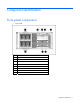
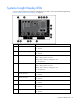
Component identification Front panel components • Rack model Item Description 1 Hard drive bays 9-16 (optional drive cage) 2 USB connectors 3 HP Systems Insight Display 4 Video connector (rack model only) 5 HP Systems Insight Display ejector button 6 DVD/CD-ROM drive 7 Removable media bays 8 Hard drive bays 1-8 Component identification 7
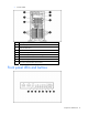
• Tower model Item Description 1 Media bay spacer 2 DVD/CD-ROM drive 3 Removable media bays 4 Hard drive bays 1-8 5 Hard drive bays 9-16 (optional drive cage) 6 USB connectors 7 HP Systems Insight Display 8 HP Systems Insight Display ejector button Front panel LEDs and buttons Component identification 8
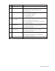
Item Description Status 1 UID button — 2 UID LED Blue = Activated Flashing blue = System is being managed remotely Off = Deactivated 3 Internal system health LED Green = Normal (system on) Amber = System health is degraded Red = System health is critical Off = Normal (system off) 4 External system health LED (power supply) Green = Normal (system on) Amber = Redundant power supply failure Red = Power supply failure. No operational power supplies.
Systems Insight Display LEDs To view a quick reference for component identification and status, access the Systems Insight Display ("Access the HP Systems Insight Display" on page 20).
Item Description Status 10 PPM 2 LED Amber = Failure Off = Normal 11 Hot-plug fan LEDs Amber = Failure or fan is not installed Off = Normal 12 Internal system health LED Green = Normal (system on) Amber = System health is degraded Red = System health is critical Off = Normal (system off) 13 External system health LED (power supply) Green = Normal (system on) Amber = Redundant power supply failure Red = Power supply failure. No operational power supplies.
Item Description 5 Video connector 6 Serial connector 7 NIC 2 connector 8 PCI expansion slots 9 Hot-plug power supply (primary bay) 10 Hot-plug power supply blank (redundant bay) 11 NIC 1 connector 12 T-10/T-15 Torx screwdriver Rear panel LEDs Item Description Status 1 UID LED Blue = Activated Flashing blue = system is being remotely managed Off = Deactivated 2 iLO 2 activity LED Green or flashing green = Network activity Off = No network activity 3 iLO 2 link LED Green = Linke
Item Description Status 7 NIC 1 activity LED Green or flashing green = Network activity Off = No network activity 8 Power supply LED Green = System has AC power and is powered up Off = System has no AC power System board components Item Description 1 PCI Express slot 1, x4 2 PCI-X slot 2, 64-bit/133-MHz 3 PCI-X slot 3, 64-bit/133-MHz 4 PCI Express slot 4, x4 5 PCI Express slot 5, x4 (optional x8 when PCIe Bus Expander is installed in slot 4) 6 PCI Express slot 6, x4 7 PCI Express sl
Item Description 16 Power connector 17 Fan control/HP Systems Insight Display connector 18 USB tape drive connector 19 IDE connector 20 Processor 2 21 PPM 2 22 Power connector 23 Front video connector 24 Internal USB connector 25 Serial 2 connector 26 Parallel connector 27 Diskette drive connector System maintenance switch Position Default Function S1 Off Off = iLO 2 security is enabled. On = iLO 2 security is disabled. S2 Off Off = System configuration can be modified.
NOTE: The system management driver must be installed for the internal system health LED to provide pre-failure and warranty conditions. The front panel health LEDs indicate only the current hardware status. In some situations, HP SIM may report server status differently than the health LEDs because the software tracks more system attributes.
HP recommends populating hard drive bays starting with the lowest SAS or SATA device number.
SAS and SATA hard drive LED combinations Online/activity LED (green) Fault/UID LED (amber/blue) On, off, or flashing Alternating amber and The drive has failed, or a predictive failure alert has been blue received for this drive; it also has been selected by a management application. On, off, or flashing Steadily blue The drive is operating normally, and it has been selected by a management application. On Amber, flashing regularly (1 Hz) A predictive failure alert has been received for this drive.
FBDIMM slots The server supports two memory boards, each containing eight slots with paired banks identified by the letters A through D. Item Description 1 FBDIMM slot 1, bank A 2 FBDIMM slot 2, bank B 3 FBDIMM slot 3, bank C 4 FBDIMM slot 4, bank D 5 FBDIMM slot 5, bank A 6 FBDIMM slot 6, bank B 7 FBDIMM slot 7, bank C 8 FBDIMM slot 8, bank D For installation requirements, refer to "FBDIMM installation guidelines (on page 48)".
Power supply backplane LED If the power supply backplane LED is illuminated, the power supply backplane has failed.
Operations Power up the server To power up the server, press the Power On/Standby button. Power down the server WARNING: To reduce the risk of personal injury, electric shock, or damage to the equipment, remove the power cord to remove power from the server. The front panel Power On/Standby button does not completely shut off system power. Portions of the power supply and some internal circuitry remain active until AC power is removed.
Open or remove the tower bezel This server has a removable bezel that must be unlocked and opened before accessing the hard drives or removing the access panel. The bezel should be kept closed during normal server operations. Use the key provided with the server to unlock the bezel with a counterclockwise turn. If necessary, remove the tower bezel.
For operations involving removable media bay access, the media bay panel may be removed. Extend the server from the rack IMPORTANT: If the server is installed in a telco rack, remove the server from the rack to access internal components. NOTE: If the server is in a rack and in the shipping configuration, remove the two shipping screws directly behind the levers. 1. Release the two levers on the lower outside corners of the server. 2.
WARNING: To reduce the risk of personal injury or equipment damage, be sure that the rack is adequately stabilized before extending a component from the rack. WARNING: To reduce the risk of personal injury, be careful when pressing the server railrelease latches and sliding the server into the rack. The sliding rails could pinch your fingers. 3. After performing the installation or maintenance procedure, press the server rail-release latches and slide the server into the rack.
5. Remove the two thumbscrews that secure the rack bezel to the top of the chassis. 6. Pull the rack bezel away from the chassis.
Install the rack bezel 1. Align the four hooks on the rack bezel with the keyholes on the metal frame, and install the rack bezel. 2. Tighten both internal rack bezel thumbscrews. Remove the access panel WARNING: To reduce the risk of personal injury from hot surfaces, allow the drives and the internal system components to cool before touching them. CAUTION: Do not operate the server for long periods with the access panel open or removed.
1. Extend the server from the rack, if applicable ("Extend the server from the rack" on page 22). 2. Open the locking latch, slide the access panel to the rear of the chassis, and remove the access panel. NOTE: If the locking latch is locked, use a Torx T-15 screwdriver to unlock the latch. Install the access panel 1. Place the access panel on top of the server with the hood latch open. Allow the panel to extend past the rear of the server approximately 0.8 cm (0.2 in). 2.
4. Remove the processor air baffle. Remove the center wall 1. Power down the server (on page 20). 2. Extend or remove the server from the rack ("Extend the server from the rack" on page 22). 3. Remove the access panel. ("Remove the access panel" on page 25) 4. Remove the processor air baffle (on page 26). 5. Remove the full-length expansion boards. 6. Lift the center wall retaining latch. 7. Remove the center wall.
Setup Optional installation services Delivered by experienced, certified engineers, HP Care Pack services help you keep your servers up and running with support packages tailored specifically for HP ProLiant systems. HP Care Packs let you integrate both hardware and software support into a single package. A number of service level options are available to meet your needs.
Optimum environment When installing the server, select a location that meets the environmental standards described in this section. Space and airflow requirements Tower server In a tower configuration, leave at least a 7.6-cm (3-in) clearance space at the front and back of the server for proper ventilation. Rack server To allow for servicing and adequate airflow, observe the following space and airflow requirements when deciding where to install a rack: • Leave a minimum clearance of 63.
Temperature requirements To ensure continued safe and reliable equipment operation, install or position the system in a wellventilated, climate-controlled environment. The maximum recommended ambient operating temperature (TMRA) for most server products is 35°C (95°F). The temperature in the room where the rack is located must not exceed 35°C (95°F).
Furthermore, you must be sure that all power distribution devices used in the installation, such as branch wiring and receptacles, are listed or certified grounding-type devices. Because of the high ground-leakage currents associated with multiple servers connected to the same power source, HP recommends the use of a PDU that is either permanently wired to the building’s branch circuit or includes a nondetachable cord that is wired to an industrial-style plug.
WARNING: To reduce the risk of personal injury, electric shock, or damage to the equipment, remove the power cord to remove power from the server. The front panel Power On/Standby button does not completely shut off system power. Portions of the power supply and some internal circuitry remain active until AC power is removed. CAUTION: Protect the server from power fluctuations and temporary interruptions with a regulating uninterruptible power supply (UPS).
• Operating system or application software • PDU Installing hardware options Install any hardware options before initializing the server. For options installation information, refer to the option documentation. For server-specific information, refer to "Hardware options installation (on page 36)." Setting up a tower server Follow the steps in this section to set up a tower model server.
WARNING: To reduce the risk of electric shock or damage to the equipment: • Do not disable the power cord grounding plug. The grounding plug is an important safety feature. • Plug the power cord into a grounded (earthed) electrical outlet that is easily accessible at all times. • Unplug the power cord from the power supply to disconnect power to the equipment. • Do not route the power cord where it can be walked on or pinched by items placed against it.
• Press the F9 key when prompted during the boot process to change the server settings using RBSU. The system is set up by default for the English language. For more information on the automatic configuration, refer to the HP ROM-Based Setup Utility User Guide located on the Documentation CD. Installing the operating system To operate properly, the server must have a supported operating system. For the latest information on supported operating systems, refer to the HP website (http://www.hp.
Hardware options installation Introduction If more than one option is being installed, read the installation instructions for all the hardware options and identify similar steps to streamline the installation process. WARNING: To reduce the risk of personal injury from hot surfaces, allow the drives and the internal system components to cool before touching them. CAUTION: To prevent damage to electrical components, properly ground the server before beginning any installation procedure.
4. Remove the processor air baffle. 5. Open the heatsink retaining latches.
6. Open the processor retaining latch and the processor socket retaining bracket. 7. Remove the processor socket protective cover. IMPORTANT: Be sure the processor remains inside the processor installation tool.
8. If the processor has separated from the installation tool, carefully re-insert the processor in the tool. 9. Align the processor installation tool with the socket and install the processor.
10. Press down firmly until the processor installation tool clicks and separates from the processor, and then remove the processor installation tool. 11. Close the processor socket retaining bracket and the processor retaining latch. 12. Remove the protective cover from the heatsink. CAUTION: To prevent thermal instability and damage to the server, do not separate the processor from the heatsink after assembling.
13. Install the heatsink. NOTE: Your heatsink may appear different than shown. 14. Close the heatsink retaining latches. 15. Install the PPM. CAUTION: To prevent thermal instability and damage to the server, be sure the Mylar shield located on the air baffle covers PPM slot 2 when PPM 2 is not installed. Remove the shield only to install a PPM.
NOTE: The appearance of compatible PPMs may vary. 16. Install the processor air baffle. 17. Install the access panel (on page 26). 18. Do one of the following: 19. o Close or install the tower bezel, as needed. o Slide the server back into the rack. Power up the server (on page 20). Memory options This server supports two memory boards. Each memory board contains 8 DIMM slots for a total of 16 DIMM slots in the server. You can expand server memory by installing supported DDR-2 FBDIMMs.
The Advanced Memory Protection option is configured in RBSU. By default, the server is set to Advanced ECC mode. For more information, refer to HP ROM-Based Setup Utility (on page 82). If the configured AMP mode is not supported by the installed FBDIMM configuration, the system boots in Advanced ECC mode. The following configuration requirements apply to all AMP modes: • FBDIMMS must be ECC Registered DDR-2 SDRAM FBDIMMs. • FBDIMMs must be installed in pairs.
Memory board 1 configuration Bank A Bank B Bank C Bank D 1A and 5A 2B and 6B 3C and 7C 4D and 8D 4 X X X X Bank A Bank B Bank C Bank D 1A and 5A 2B and 6B 3C and 7C 4D and 8D X — — — — — — — X — — — X — — — X X — — X — — — X X — — X X — — X X X — X X — — X X X — X X X — X X X X X X X — X X X X X X X X Dual memory board configuration: Memory board 1 configuration Memory board 2 configuration 1 2 3 4 5 6 7 8 Online spare me
If one of the non-spare FBDIMMs receives correctable memory errors at a higher rate than a specific threshold, the server automatically copies the memory contents of the degraded rank to the online spare rank. The server then deactivates the failing rank and automatically switches over to the online spare.
memory read on one memory board returns incorrect data due to an uncorrectable memory error, the system automatically retrieves the proper data from the other memory board. A memory board is not necessarily disabled (thus losing mirroring protection) because of a single uncorrectable error. Mirroring protection is not lost due to transient and soft uncorrectable errors, resulting in systems that maintain mirroring protection (and thus improved uptime) unless there is a true FBDIMM failure.
WARNING: To prevent personal injury from hazardous energy: • Remove watches, rings, or other metal objects. • Use tools with insulated handles. • Do not place tools or metal parts on top of batteries. Removing and installing a memory board 1. Power down the server (on page 20). 2. Do one of the following: o Open or remove the tower bezel, as needed ("Open or remove the tower bezel" on page 21). o Extend the server from the rack (on page 22). 3. Remove the access panel (on page 25). 4.
8. Install the memory board. 9. Install the processor air baffle. 10. Install the access panel (on page 26). 11. Do one of the following: o Close or install the tower bezel, as needed. o Slide the server back into the rack. 12. Power up the server. 13. Configure the memory. FBDIMM installation guidelines Always observe the following guidelines when installing additional memory: • Always install memory in pairs of equal capacity. • Install FBDIMMs into both slots within a single bank.
3. Remove the access panel (on page 25). 4. Remove the processor air baffle (on page 26). 5. Remove a memory board ("Removing and installing a memory board" on page 47). 6. Remove the FBDIMM. To replace the component, reverse the removal procedure. Installing FBDIMMs 1. Power down the server (on page 20). 2. Do one of the following: o Open or remove the tower bezel, as needed ("Open or remove the tower bezel" on page 21). o Extend the server from the rack (on page 22). 3.
7. Install the FBDIMM. 8. Install the memory board ("Removing and installing a memory board" on page 47). 9. Install the processor air baffle. 10. Install the access panel (on page 26). 11. Do one of the following: 12. o Close or install the tower bezel, as needed. o Slide the server back into the rack. If you are installing FBDIMMs in an online spare or mirrored memory configuration, use RBSU to configure this feature ("Configuring online spare memory" on page 83).
Installing a hot-plug hard drive 1. Remove the hard drive blank. 2. Prepare the hard drive.
3. Install the hard drive. 4. Determine the status of the hard drive from the hot-plug SAS hard drive LED combinations ("SAS and SATA hard drive LED combinations" on page 17). Removing a hot-plug hard drive CAUTION: To prevent improper cooling and thermal damage, do not operate the server unless all bays are populated with either a component or a blank. 1. Determine the status of the hard drive from the hot-plug SAS hard drive LED combinations ("SAS and SATA hard drive LED combinations" on page 17).
SAS-SATA hard drive cage option NOTE: An optional SAS controller is required to support the SAS-SATA hard drive cage installation. 1. Power down the server. ("Power down the server" on page 20) 2. Do one of the following: o Open or remove the tower bezel, as needed ("Open or remove the tower bezel" on page 21). o Extend the server from the rack (on page 22). 3. Remove the access panel (on page 25). 4. For rack models, remove the bezel ("Remove the rack bezel" on page 23). 5.
9. Slide the hard drive cage into the drive bay and insert the four screws to secure the drive cage to the chassis. 10. Connect the two SAS-SATA data cables to the drive cage backplane. IMPORTANT: When installing a x3/x1 SAS cable, HP recommends that the x3 part of the x3/x1 cable be linked to the SAS hard drive backplane connector that corresponds to hard drive slots 1 to 4.
12. For rack models, install the rack bezel. 13. Install the access panel (on page 26). 14. Install hard drives ("Installing a hot-plug hard drive" on page 51) or hard drive blanks, as needed. 15. Do one of the following: o Close or install the tower bezel, as needed. o Slide the server back into the rack. CAUTION: To prevent improper cooling and thermal damage, do not operate the server unless all bays are populated with either a component or a blank.
3. Remove the media blanks. NOTE: HP recommends that you remove all media blanks to facilitate drive installation. Store the blanks for later use. Installing a half-height or full-height media device You can install up to two half-height or one full-height removable media devices in the removable media cage. To install a half-height or full-height media device: 1. Power down the server (on page 20). 2.
5. Using the T-15 Torx screwdriver, remove the screws from the bezel blank and install them on the device. 6. Slide the media device part of the way into the bay.
o Full-height device 7. Connect the four-pin power cable to the half-height or full-height drive. 8. Connect the data and power cables to the device. 9. Connect the power cable to the system board. 10. Connect the data cable to the system board or to an expansion board as directed by the option documentation. 11. Slide the media drive fully into the bay until it is seated securely. 12.
14. Install the access panel (on page 26). 15. Do one of the following: 16. o Close or install the tower bezel, as needed. o Slide the server back into the rack. Power up the server (on page 20). Redundant hot-plug fans option The server supports redundant hot-plug fans to provide proper airflow to the system if a primary fan fails. In the standard, non-redundant, configuration, fans 1, 2, and 3 cool the server.
4. Install the access panel (on page 26). 5. Do one of the following: o Close or install the tower bezel, as needed. o Slide the server back into the rack. Redundant hot-plug power supply option The server supports a second hot-plug power supply to provide redundant power to the system in the event of a failure in the primary power supply. CAUTION: If only one power supply is installed, do not remove the power supply unless the server has been powered down.
3. Install the second hot-plug power supply. 4. Connect the power cord to the redundant power supply. 5. Use the power cord management clip to secure the cord and form a service loop. 6. Connect the power cord to the power source. 7. Be sure that the power supply LED is green ("Rear panel LEDs" on page 12). 8. Be sure that the front panel external health LED is green ("Front panel LEDs and buttons" on page 8).
Slot Expansion card type Connector Speed 1 PCI Express x8 x4 2 PCI-X 64-bit, 3.3-V 133-MHz capable 3 PCI-X 64-bit, 3.
2. Extend the server from the rack, if applicable ("Extend the server from the rack" on page 22). 3. Remove the access panel (on page 25). 4. Press the slot release lever and swing the slot release lever upward. 5. Remove the expansion slot cover. Retain the slot cover for future use. CAUTION: To prevent improper cooling and thermal damage, do not operate the server unless all PCI slots have either an expansion slot cover or an expansion board installed.
5. Release the retainer clip. 6. Install the expansion board. 7. Close the slot release lever and lock the retainer clip. 8. Connect any required internal or external cables to the expansion board. Refer to the documentation that ships with the expansion board. 9. Install the access panel (on page 26). 10. Do one of the following: o Close or install the tower bezel, as needed. o Slide the server back into the rack.
To remove the component: 1. Power down the server (on page 20). 2. Extend the server from the rack, if applicable ("Extend the server from the rack" on page 22). 3. Remove the access panel (on page 25). 4. Disconnect any cables attached to the expansion board. 5. Release the retainer clip. 6. Press the slot release lever and swing the slot release lever upward. 7. Remove the expansion board. CAUTION: Make a note of board locations. Be sure to install replacements in the same slots.
Array controllers and Battery-Backed Write Cache options For a list of supported options, refer to the Documentation CD or the QuickSpecs on the HP website (http://www.hp.com/servers/proliantml370). Parallel and second serial connector option To install the component: 1. Power down the server (on page 20). 2. Do one of the following: o Open or remove the tower bezel, as needed ("Open or remove the tower bezel" on page 21). o Extend the server from the rack (on page 22). 3.
Tower-to-rack conversion option The tower-to-rack conversion kit includes all equipment required to convert the tower model server into a rack model server and to install the server into most square- or round-hole racks. The tower-to-rack conversion kit includes: • Rack rails • Cable management arm • Server rails • Rack bezel • Front video connector cable In addition to the items supplied in the conversion kit, you will also need a Torx T-15 screwdriver (clipped to the rear panel of the server).
b. Remove the tower configuration panels. 5. Remove the media blanks. 6. Remove the access panel (on page 25). 7. Remove the center wall (on page 27). 8. Remove the CD-ROM drive. a. Press and slide the media latch.
b. Release the CD-ROM drive from the back and push it forward to better access the cables. c. Disconnect the IDE CD-ROM drive cable and power cable from the back of the drive. d. Remove the CD-ROM drive.
9. Press and slide the media latch to remove the media bay spacer. 10. Remove the two clips on the server.
11. Align the four hooks on the rack bezel with the keyholes on the metal frame, and install the rack bezel. 12. Tighten both internal rack bezel thumbscrews. 13. Partially insert the CD-ROM drive horizontally into the slot below the media bay spacer.
14. Connect the IDE CD-ROM drive cable and power cable. 15. Push the CD-ROM drive all the way into the bay until the locking latch clicks into place, securing the drive. 16. Install the media blanks horizontally in the bay below the CD-ROM drive. NOTE: Install any optional tape drives ("Installing a half-height or full-height media device" on page 56) instead of the media blanks at this time. 17. Remove the video connector blank from the media bay spacer.
18. Install the front video connector and thread the cable through the clip on the media bay spacer. 19. Install the media bay spacer into the top slot of the media bay.
20. Connect the front video connector cable to the internal video connector. 21. Install the center wall. 22. Install the access panel (on page 26). 23. Install the server into the rack ("Installing the server into the rack" on page 34).
Cabling Storage device cabling guidelines CAUTION: To prevent damage to the equipment, be sure that the server is powered down, all cables are disconnected from the back of the server, and the power cord is disconnected from the grounded (earthed) AC outlet before installing devices. CAUTION: To prevent damage to electrical components, properly ground the server before beginning any installation procedure. Improper grounding can cause electrostatic discharge.
Item Description 10 SAS drive connector (9-12) SAS cabling NOTE: The center wall is removed for illustration purposes only. • SAS data cabling IMPORTANT: When installing a x3/x1 SAS cable, HP recommends that the x3 part of the x3/x1 cable be linked to the SAS hard drive backplane connector that corresponds to hard drive slots 1 to 4. In this setup, hard drive slot 1 will not be available, but since hard drive slots 2 to 4 will be connected, one continuous volume can be created.
• SAS power cabling CD-ROM drive cabling Cabling 77
Video cabling Parallel/serial port cabling Cabling 78
Diskette drive cabling BBWC option cabling Cabling 79
Internal USB connector Cabling 80
Configuration and utilities Configuration tools SmartStart software SmartStart is a collection of software that optimizes single-server setup, providing a simple and consistent way to deploy server configuration. SmartStart has been tested on many ProLiant server products, resulting in proven, reliable configurations.
Configuration Replication Utility CONREP is shipped in the SmartStart Scripting Toolkit and is a program that works with RBSU to replicate hardware configuration on ProLiant servers. This utility is run during State 0, Run Hardware Configuration Utility, when doing a scripted server deployment. CONREP reads the state of the system environment variables to determine the configuration and then writes the results to an editable script file.
Boot options Near the end of the boot process, the boot options screen is displayed. This screen is visible for several seconds before the system attempts to boot from a diskette, CD, or hard drive.
For more information on mirrored memory, refer to the white paper on the HP website (http://h18000.www1.hp.com/products/servers/technology/memoryprotection.html).
NOTE: The server may not support all the following examples. NOTE: If the boot drive is not empty or has been written to in the past, ORCA does not automatically configure the array. You must run ORCA to configure the array settings. Drives Installed Drives Used RAID Level 1 1 RAID 0 2 2 RAID 1 3, 4, 5, or 6 3, 4, 5, or 6 RAID 5 More than 6 0 None To change any ORCA default settings and override the auto-configuration process, press the F8 key when prompted.
8. Press the Esc key to close the menu. 9. Press the Esc key to exit RBSU. 10. Press the F10 key to confirm exiting RBSU. The server will automatically reboot. Management tools Automatic Server Recovery ASR is a feature that causes the system to restart when a catastrophic operating system error occurs, such as a blue screen, ABEND, or panic. A system fail-safe timer, the ASR timer, starts when the System Management driver, also known as the Health Driver, is loaded.
Integrated Lights-Out technology The iLO 2 subsystem is a standard component of selected ProLiant servers that provides server health and remote server manageability. The iLO 2 subsystem includes an intelligent microprocessor, secure memory, and a dedicated network interface. This design makes iLO 2 independent of the host server and its operating system. The iLO 2 subsystem provides remote access to any authorized network client, sends alerts, and provides other server management functions.
StorageWorks library and tape tools HP StorageWorks L&TT provides functionality for firmware downloads, verification of device operation, maintenance procedures, failure analysis, corrective service actions, and some utility functions. It also provides seamless integration with HP hardware support by generating and emailing support tickets that deliver a snapshot of the storage system. For more information, and to download the utility, refer to the StorageWorks L&TT website (http://h18006.www1.hp.
Access to redundant ROM settings To access the redundant ROM through RBSU: 1. Access RBSU by pressing the F9 key during powerup when the prompt is displayed in the upper right corner of the screen. 2. Select Advanced Options. 3. Select Redundant ROM Selection. 4. Select the ROM version. 5. Press the Enter key. 6. Press the Esc key to exit the current menu or press the F10 key to exit RBSU. The server restarts automatically. To access the redundant ROM manually: 1.
• Diagnostics • DOS • Operating environments which do not provide native USB support For more information on ProLiant USB support, refer to the HP website (http://h18004.www1.hp.com/products/servers/platforms/usb-support.html). Internal USB functionality An internal USB connector is available for use with USB drive keys only.
HP Insight Diagnostics Offline Edition performs various in-depth system and component testing while the OS is not running. To run this utility, launch the SmartStart CD. HP Insight Diagnostics Online Edition is a web-based application that captures system configuration and other related data needed for effective server management. Available in Microsoft® Windows® and Linux versions, the utility helps to ensure proper system operation.
Keeping the system current Drivers The server includes new hardware that may not have driver support on all operating system installation media. If you are installing a SmartStart-supported operating system, use the SmartStart software (on page 81) and its Assisted Path feature to install the operating system and latest driver support. NOTE: If you are installing drivers from the SmartStart CD or the Software Maintenance CD, refer to the SmartStart website (http://www.hp.
Care Pack HP Care Pack Services offer upgraded service levels to extend and expand standard product warranty with easy-to-buy, easy-to-use support packages that help you make the most of your server investments. Refer to the Care Pack website (http://www.hp.com/hps/carepack/servers/cp_proliant.html).
Battery replacement If the server no longer automatically displays the correct date and time, you may need to replace the battery that provides power to the real-time clock. Under normal use, battery life is 5 to 10 years. WARNING: The computer contains an internal lithium manganese dioxide, a vanadium pentoxide, or an alkaline battery pack. A risk of fire and burns exists if the battery pack is not properly handled. To reduce the risk of personal injury: • Do not attempt to recharge the battery.
For more information about battery replacement or proper disposal, contact an authorized reseller or an authorized service provider.
Troubleshooting Troubleshooting resources The HP ProLiant Servers Troubleshooting Guide provides simple procedures for resolving common problems as well as a comprehensive course of action for fault isolation and identification, error message interpretation, issue resolution, and software maintenance.
Symbols on equipment The following symbols may be placed on equipment to indicate the presence of potentially hazardous conditions. This symbol indicates the presence of hazardous energy circuits or electric shock hazards. Refer all servicing to qualified personnel. WARNING: To reduce the risk of injury from electric shock hazards, do not open this enclosure. Refer all maintenance, upgrades, and servicing to qualified personnel. This symbol indicates the presence of electric shock hazards.
WARNING: To reduce the risk of personal injury or damage to the equipment, be sure that: • The leveling feet are extended to the floor. • The full weight of the rack rests on the leveling feet. • The stabilizing feet are attached to the rack if it is a single-rack installation. • The racks are coupled together in multiple-rack installations. • Only one component is extended at a time. A rack may become unstable if more than one component is extended for any reason.
To answer these questions, the following information may be useful: • Run HP Insight Diagnostics (on page 90) and use the survey page to view the current configuration or to compare it to previous configurations. • Refer to your hardware and software records for information. • Refer to server LEDs and their statuses. Prepare the server for diagnosis 1. Be sure the server is in the proper operating environment with adequate power, air conditioning, and humidity control.
• Check any interlock or interconnect LEDs that may indicate a component is not connected properly. • If problems continue to occur, remove and reinstall each device, checking the connectors and sockets for bent pins or other damage. Service notifications To view the latest service notifications, refer to the HP website (http://www.hp.com/go/bizsupport). Select the appropriate server model, and then click the Troubleshoot a Problem link on the product page.
General diagnosis flowchart The General diagnosis flowchart provides a generic approach to troubleshooting. If you are unsure of the problem, or if the other flowcharts do not fix the problem, use the following flowchart.
Item Refer to 4 The most recent version of a particular server or option firmware is available on the following websites: • HP Support website (http://www.hp.com/support) • HP ROM-BIOS/Firmware Updates website (http://h18023.www1.hp.com/support/files/server/us/romflash.ht ml) 5 "General memory problems are occurring" in the HP ProLiant Servers Troubleshooting Guide located on the Documentation CD or on the HP website (http://www.hp.
Server power-on problems flowchart Symptoms: • The server does not power on. • The system power LED ("Systems Insight Display LEDs" on page 10) is off or amber.
• The external health LED ("Systems Insight Display LEDs" on page 10) is red or amber. • The internal health LED ("Systems Insight Display LEDs" on page 10) is red or amber. NOTE: For the location of server LEDs and information on their statuses, refer to the server documentation.
Troubleshooting 105
POST problems flowchart Symptoms: • Server does not complete POST NOTE: The server has completed POST when the system attempts to access the boot device.
OS boot problems flowchart Symptoms: • Server does not boot a previously installed operating system • Server does not boot SmartStart Possible causes: • Corrupted operating system • Hard drive subsystem problem • Incorrect boot order setting in RBSU Troubleshooting 107
Item Refer to 1 HP ROM-Based Setup Utility User Guide (http://www.hp.com/servers/smartstart) 2 "POST problems flowchart (on page 106)" 3 • "Hard drive problems" in the HP ProLiant Servers Troubleshooting Guide located on the Documentation CD or on the HP website (http://www.hp.com/support) • Controller documentation 4 "HP Insight Diagnostics (on page 90)" or in the HP ProLiant Servers Troubleshooting Guide located on the Documentation CD or on the HP website (http://www.hp.
Server fault indications flowchart Symptoms: • Server boots, but a fault event is reported by Insight Management Agents (on page 88) • Server boots, but the internal health LED, external health LED, or component health LED is red or amber Troubleshooting 109
NOTE: For the location of server LEDs and information on their statuses, refer to the server documentation. Possible causes: • Improperly seated or faulty internal or external component • Unsupported component installed • Redundancy failure • System overtemperature condition Item Refer to 1 "Management agents (on page 88)" or in the HP ProLiant Servers Troubleshooting Guide located on the Documentation CD or on the HP website (http://www.hp.
POST error messages and beep codes For a complete listing of error messages, refer to the "POST error messages" in the HP ProLiant Servers Troubleshooting Guide located on the Documentation CD or on the HP website (http://www.hp.com/support).
Electrostatic discharge Preventing electrostatic discharge To prevent damaging the system, be aware of the precautions you need to follow when setting up the system or handling parts. A discharge of static electricity from a finger or other conductor may damage system boards or other static-sensitive devices. This type of damage may reduce the life expectancy of the device. To prevent electrostatic damage: • Avoid hand contact by transporting and storing products in static-safe containers.
Regulatory compliance notices Regulatory compliance identification numbers For the purpose of regulatory compliance certifications and identification, this product has been assigned a unique regulatory model number. The regulatory model number can be found on the product nameplate label, along with all required approval markings and information. When requesting compliance information for this product, always refer to this regulatory model number.
energy and, if not installed and used in accordance with the instructions, may cause harmful interference to radio communications. However, there is no guarantee that interference will not occur in a particular installation.
Canadian notice (Avis Canadien) Class A equipment This Class A digital apparatus meets all requirements of the Canadian Interference-Causing Equipment Regulations. Cet appareil numérique de la classe A respecte toutes les exigences du Règlement sur le matériel brouilleur du Canada. Class B equipment This Class B digital apparatus meets all requirements of the Canadian Interference-Causing Equipment Regulations.
Disposal of waste equipment by users in private households in the European Union This symbol on the product or on its packaging indicates that this product must not be disposed of with your other household waste. Instead, it is your responsibility to dispose of your waste equipment by handing it over to a designated collection point for the recycling of waste electrical and electronic equipment.
Korean notice Class A equipment Class B equipment Laser compliance This product may be provided with an optical storage device (that is, CD or DVD drive) and/or fiber optic transceiver. Each of these devices contains a laser that is classified as a Class 1 Laser Product in accordance with US FDA regulations and the IEC 60825-1. The product does not emit hazardous laser radiation. Each laser product complies with 21 CFR 1040.10 and 1040.11 except for deviations pursuant to Laser Notice No.
WARNING: The computer contains an internal lithium manganese dioxide, a vanadium pentoxide, or an alkaline battery pack. A risk of fire and burns exists if the battery pack is not properly handled. To reduce the risk of personal injury: • Do not attempt to recharge the battery. • Do not expose the battery to temperatures higher than 60°C (140°F). • Do not disassemble, crush, puncture, short external contacts, or dispose of in fire or water.
Specifications Server specifications Specification Value Dimensions Rack model — Height 21.92 cm (8.63 in) Depth 65.41 cm (26.5 in) Width 44.45 cm (17.50 in) Tower model — Height 47 cm (18.5 in) Depth 71.1 cm (28 in) Width 21.92 cm (8.63 in) Weight Weight (maximum) 40.8 kg (110 lb) Weight (when lightly loaded) 24.9 kg (55 lb) Input requirements Rated input voltage 100 VAC to 240 VAC * Rated input frequency 47 Hz to 63 Hz Rated input current 10 A (100 V) to 6.
Specification Value Relative humidity (noncondensing)** Operating 10% to 90% Non-operating 5% to 95% * All temperature ratings shown are for sea level. An altitude derating of 1°C per 300 m (1.8°F per 1,000 ft) to 3048 m (10,000 ft) is applicable. No direct sunlight allowed. ** Storage maximum humidity of 95% is based on a maximum temperature of 45°C (113°F). Altitude maximum for storage corresponds to a pressure minimum of 70 KPa.
Technical support Related documents For related documentation, refer to the Documentation CD.
Customer Self Repair HP products are designed with many Customer Self Repair (CSR) parts to minimize repair time and allow for greater flexibility in performing defective parts replacement. If during the diagnosis period HP (or HP service providers or service partners) identifies that the repair can be accomplished by the use of a CSR part, HP will ship that part directly to you for replacement. There are two categories of CSR parts: • Mandatory—Parts for which customer self repair is mandatory.
Les pièces CSR sont livrées le jour ouvré suivant, dans la limite des stocks disponibles et selon votre situation géographique. Si votre situation géographique le permet et que vous demandez une livraison le jour même ou dans les 4 heures, celle-ci vous sera facturée. Pour bénéficier d'une assistance téléphonique, appelez le Centre d'assistance technique HP. Dans les documents envoyés avec la pièce de rechange CSR, HP précise s'il est nécessaire de lui retourner la pièce défectueuse.
kann, sendet Ihnen HP dieses Bauteil zum Austausch direkt zu. CSR-Teile werden in zwei Kategorien unterteilt: • Zwingend – Teile, für die das Customer Self Repair-Verfahren zwingend vorgegeben ist. Wenn Sie den Austausch dieser Teile von HP vornehmen lassen, werden Ihnen die Anfahrt- und Arbeitskosten für diesen Service berechnet. • Optional – Teile, für die das Customer Self Repair-Verfahren optional ist. Diese Teile sind auch für Customer Self Repair ausgelegt.
Según la disponibilidad y la situación geográfica, los componentes CSR se enviarán para que lleguen a su destino al siguiente día laborable. Si la situación geográfica lo permite, se puede solicitar la entrega en el mismo día o en cuatro horas con un coste adicional. Si precisa asistencia técnica, puede llamar al Centro de asistencia técnica de HP y recibirá ayuda telefónica por parte de un técnico.
Reparo feito pelo cliente Os produtos da HP são projetados com muitas peças para reparo feito pelo cliente (CSR) de modo a minimizar o tempo de reparo e permitir maior flexibilidade na substituição de peças com defeito. Se, durante o período de diagnóstico, a HP (ou fornecedores/parceiros de serviço da HP) concluir que o reparo pode ser efetuado pelo uso de uma peça CSR, a peça de reposição será enviada diretamente ao cliente.
Technical support 127
Technical support 128
Acronyms and abbreviations ABEND abnormal end ACU Array Configuration Utility AMP Advanced Memory Protection ASR Automatic Server Recovery BBWC battery-backed write cache DDR double data rate DIMM dual inline memory module ECC error checking and correcting FBDIMM fully buffered DIMM IEC International Electrotechnical Commission iLO 2 Integrated Lights-Out 2 IML Integrated Management Log Acronyms and abbreviations 129
NEMA National Electrical Manufacturers Association NFPA National Fire Protection Association NIC network interface controller NVRAM non-volatile memory ORCA Option ROM Configuration for Arrays PCI-X peripheral component interconnect extended PDU power distribution unit POST Power-On Self Test PPM processor power module PSP ProLiant Support Pack RBSU ROM-Based Setup Utility SIM Systems Insight Manager TMRA recommended ambient operating temperature UID unit identification Acronyms and abbreviati
VHDCI very high density cable interconnect Acronyms and abbreviations 131
Index A AC power supply 12, 60 access panel 25, 26 ACU (Array Configuration Utility) 84 additional information 96, 121 ADU (Array Diagnostic Utility) 90 air baffle 26 Altiris Deployment Solution 85 Altiris eXpress Deployment Server 85 Array Configuration Utility (ACU) 84 array controllers 66 Array Diagnostic Utility (ADU) 90 ASR (Automatic Server Recovery) 86 authorized reseller 121 Automatic Server Recovery (ASR) 86 Autorun menu 81 B battery 13, 117 battery-backed write cache battery-backed write cache ba
features 7 Federal Communications Commission (FCC) notice 113, 114 flowcharts 100, 101, 103, 106, 107, 109 front panel buttons 8 front panel components 7 front panel LEDs 8 G general diagnosis flowchart 101 grounding methods 112 grounding requirements 30 H Hard drive cage option 53 hard drive LEDs 16, 17 hard drives 17 hard drives, determining status of 16, 17 hardware options 36 hardware options installation 33, 36 health driver 59, 86 health LEDs 8 help resources 121 HP Insight Diagnostics 90 HP ProLian
power requirements 30 power supplies 12, 60 power supply backplane LED 19 power supply LEDs 12, 19 powering down 20 powering up 20, 82 power-on problems flowchart 103 PPM failure LEDs 10 PPM slots 13 preparation procedures 99 problem diagnosis 96 processor air baffle 26 processor failure LEDs 10, 19 processors 13, 36 ProLiant Support Pack (PSP) 92 PSPs, overview 92 R rack installation 28, 31, 34 rack resources 28 rack stability 97 rack warnings 97 RBSU (ROM-Based Setup Utility) 82 rear panel buttons 12 rea
W warnings 97 website, HP 121 Index 135