
Instruction Manual


Hardware options installation 75
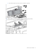
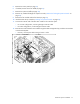
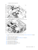
15.
Route and connect the redundant power supply, drive cage, and optical drive power cables to the
system board.
Item Cables and connectors Connector identifier
1
Optical drive power cable connector P7, P8, P9, P10
2
Processor 2 RPS backplane connector P3
3
Box 2 RPS backplane connector P5
4
2x13 RPS control cable connector
N/A
5
2x12 pin system board power cable
connector
P1
6
2x4 pin processor 2 power cable connector
P3M
7
2x4 pin processor 1 power cable connector P2
8
2x5 pin box 2 power cable connector P5H
9
2x5 pin box 1 power cable connector BP1
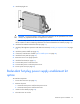
16. Install the redundant hot-plug power supply cage rear blank.