HP ProLiant ML350e Gen8 v2 Server User Guide Abstract This document is for the person who installs, administers, and troubleshoots servers and storage systems. HP assumes you are qualified in the servicing of computer equipment and trained in recognizing hazards in products with hazardous energy levels.
© Copyright 2013, 2014 Hewlett-Packard Development Company, L.P. The information contained herein is subject to change without notice. The only warranties for HP products and services are set forth in the express warranty statements accompanying such products and services. Nothing herein should be construed as constituting an additional warranty. HP shall not be liable for technical or editorial errors or omissions contained herein. Microsoft® and Windows® are U.S.
Contents Component identification ............................................................................................................... 7 Front panel components ............................................................................................................................. 7 Front panel LEDs and buttons ...................................................................................................................... 9 Rear panel components .........................................
Powering on and selecting boot options ..................................................................................................... 36 Installing the operating system................................................................................................................... 37 Registering the server ............................................................................................................................... 37 Hardware options installation .................................
Software and configuration utilities ............................................................................................... 92 Server mode ........................................................................................................................................... 92 HP product QuickSpecs............................................................................................................................ 92 HP iLO Management Engine ...............................................
Before you contact HP............................................................................................................................ 113 HP contact information ........................................................................................................................... 113 Customer Self Repair ............................................................................................................................. 113 Acronyms and abbreviations ................................
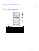
Component identification Front panel components • Non-hot-plug drive configuration Item Description 1 Optical drive 2 Optional media bay (2) 3 USB 2.
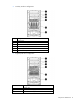
• Four-bay LFF drive configuration Item Description 1 Optical drive 2 Optional media bay (2) 3 USB 2.0 connectors (2) 4 Thermal sensor 5 LFF drives (4) 6 Optional drive bay • Eight-bay SFF drive configuration Item Description 1 Optical drive 2 Optional media bay (2) 3 USB 2.
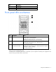
Item Description 4 Thermal sensor 5 SFF drives (8) 6 Optional drive bay Front panel LEDs and buttons Item Description Status 1 Health LED Solid green = Normal Flashing amber = System degraded Flashing red (1 Hz/cycle per sec) = System critical Fast-flashing red (4 Hz/cycles per sec) = Power fault* 2 NIC status LED Solid green = Link to network Flashing green (1 Hz/cycle per sec) = Network active Off = No network activity 3 Power On/Standby button and system power LED Solid green = System
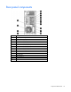
Rear panel components Item Description 1 Integrated power supply 2 Slot 6 PCIe2 x4(1) for processor 1 3 Slot 5 PCIe2 x8(4,1) for processor 1 4 Slot 4 PCIe3 x16(8,4,1) for processor 2 5 Slot 3 PCIe3 x16(16,8,4,1) for processor 2 6 Slot 2 PCIe3x16 (16,8,4,1) for processor 1 7 Slot 1 PCIe3 x8 (4,1) for processor 1 8 USB 2.
Rear panel LEDs Item Description Status 1 NIC activity LED Green = Network activity Flashing green = Network activity Off = No network activity 2 NIC link LED Green = Network link Off = No network link 3 UID LED button Blue = Activated Flashing blue = System is being managed remotely Off = Deactivated System board components Component identification 11
Item Description 1 Slot 6 PCIe2 x4 (1) 2 Slot 5 PCIe2 x8 (4,1) 3 Slot 4 PCIe3 x16 (8,4,1) 4 Slot 3 PCIe3 x16 (16,8,4,1) 5 System maintenance switch 6 Slot 2 PCIe3 x16 (16,8,4,1) 7 Slot 1 PCIe3 x8 (4,1) 8 Processor 2 DIMM slots 9 Processor socket 2 10 System battery 11 Processor 2 power connector 12 Processor socket 1 (populated) 13 Processor 1 DIMM slots 14 Internal USB connector 15 Fan connector 3 16 SD card connector 17 Internal USB tape drive connector 18 Processor 1
Position Description Function S6 Reset configuration Off = No function On = ROM reads the system configuration as invalid. S3, S4, S7-S12 — Reserved When the system maintenance switch position 6 is set to the On position, the system is prepared to erase all system configuration settings from both CMOS and NVRAM. CAUTION: Clearing CMOS and/or NVRAM deletes configuration information. Be sure to properly configure the server or data loss could occur.
For more information, see the HP website (http://www.hp.com/support/NMI). DIMM slot locations DIMM slots are numbered sequentially (1 through 6) for each processor. The supported AMP modes use the letter assignments for population guidelines.
SAS and SATA device numbers With optional drive cages installed, the server supports up to 16 SFF drives or up to 8 LFF drives. The server does not support mixing SFF and LFF drives. HP recommends that you populate drive bays starting with the lowest SAS or SATA device number. Drives are numbered from left to right in each component box. Component boxes are numbered 1 to 2 from top to bottom.
• LFF drive numbering • Four-bay + four-bay LFF drive numbering (hot-plug only) Component identification 16
• Non-hot-plug drive numbering SAS and SATA drive LED combinations Online/activity LED (green) Fault/UID LED (amber/blue) Interpretation On, off, or flashing Alternating amber and The drive has failed, or a predictive failure alert has been blue received for this drive. The drive also has been selected by a management application. On, off, or flashing Steadily blue The drive is operating normally, and it has been selected by a management application.
FBWC module LED definitions P222 and P430 modules The FBWC module has three LEDs (one amber and two green). The LEDs are duplicated on the reverse side of the FBWC module to facilitate status viewing. 1 - Amber 2 - Green 3 - Green Interpretation Off Off Off The FBWC module is not powered. Off Flashing 0.5 Hz Flashing 0.5 Hz The FBWC microcontroller is executing from within its boot loader and receiving new flash code from the host controller.
B120i module The FBWC module has three LEDs (one amber and two green). 1 - Amber 2 - Green 3 - Green Interpretation Off Off Off The FBWC module is not powered. Off Flashing 0.5 Hz Flashing 0.5 Hz The FBWC microcontroller is executing from within its boot loader and receiving new flash code from the host controller. Off Flashing 1 Hz Flashing 1 Hz The FBWC module is powering up, and the capacitor pack is charging.
Hot-plug drive LED definitions Item LED Status 1 Locate Solid blue The drive is being identified by a host application. Flashing blue The drive carrier firmware is being updated or requires an update. Rotating green Drive activity Off No drive activity Solid white Do not remove the drive. Removing the drive causes one or more of the logical drives to fail. Off Removing the drive does not cause a logical drive to fail. Solid green The drive is a member of one or more logical drives.
Fan locations Item Description Configuration 1 Fan 1 Primary 2 Fan 2 Primary 3 Fan 3 Optional Redundant power supply connectors Item Description Connector identifier 1 Optical drive power connector P7, P8, P9, P10 2 Processor 2 RPS backplane connector P3 3 Box 2 RPS backplane connector P5 Component identification 21
Item Description Connector identifier 4 RPS connector N/A 5 System board power connector P1 6 Processor 2 power connector P3M 7 Processor 1 power connector P2 8 Box 2 power connector P5H 9 Box 1 power connector BP1 Component identification 22
Operations Power up the server 1. Connect each power cord to the server. 2. Connect each power cord to the power source. 3. Press the Power On/Standby button. The server exits standby mode and applies full power to the system. The system power LED changes from amber to green. Power down the server Before powering down the server for any upgrade or maintenance procedures, perform a backup of critical server data and programs.
Unlock the front bezel Using the key provided with the server, unlock the bezel with a clockwise turn. Lock the front bezel Using the key provided with the server, lock the bezel with a counterclockwise turn. Remove the front bezel This server has a removable bezel that must be unlocked and opened before accessing the drives. The bezel must be kept closed during normal server operations.
To remove the component, unlock and remove the front bezel. Install the front bezel 1. Insert the bezel. 2. Close the bezel. 3. Using the key provided with the server, lock the bezel with a counterclockwise turn. Remove the access panel WARNING: To reduce the risk of personal injury from hot surfaces, allow the drives and the internal system components to cool before touching them.
CAUTION: For proper cooling do not operate the server without the access panel, baffles, expansion slot covers, or blanks installed. 1. Power down the server (on page 23). 2. Remove all power: a. Disconnect each power cord from the power source. b. Disconnect each power cord from the server. 3. Unlock the front bezel (on page 24). 4. Place the server on its side. 5. Remove the access panel: a. Loosen the access panel thumbscrews. b. Slide the access panel back. c.
b. Tighten the thumbscrews. 2. Return the server to an upright position. 3. Lock the front bezel (on page 24). 4. Power up the server (on page 23). Remove the PCI air baffle 1. Power down the server (on page 23). 2. Remove all power: a. Disconnect each power cord from the power source. b. Disconnect each power cord from the server. 3. Unlock the front bezel (on page 24). 4. Place the server on its side. 5. Remove the access panel (on page 25). 6. Remove the PCI air baffle.
Remove the system air baffle 1. Power down the server (on page 23). 2. Remove all power: a. Disconnect each power cord from the power source. b. Disconnect each power cord from the server. 3. Unlock the front bezel (on page 24). 4. Place the server on its side. 5. Remove the access panel (on page 25). 6. If installed, remove the PCI air baffle (on page 27). 7. Remove the system air baffle.
3. Install the access panel (on page 26). 4. Return the server to an upright position. 5. Lock the front bezel (on page 24). 6. Power up the server (on page 23). Remove the full-length expansion board 1. Power down the server (on page 23). 2. Remove all power: a. Disconnect each power cord from the power source. b. Disconnect each power cord from the server. 3. Unlock the front bezel (on page 24). 4. Place the server on its side. 5. Remove the access panel (on page 25). 6.
Remove the fan modules and the fan blank 1. Power down the server (on page 23). 2. Remove all power: a. Disconnect each power cord from the power source. b. Disconnect each power cord from the server. 3. Unlock the front bezel (on page 24). 4. Place the server on its side. 5. Remove the access panel (on page 25). 6. If installed, remove the PCI air baffle (on page 27). 7. Remove any installed full-length PCI expansion cards ("Remove the full-length expansion board" on page 29). 8.
e. Remove the fan blank. Install the fan modules and the fan blank 1. Install the fan blank and the fan modules: a. Install the fan blank. b. Install fan 2. c. Connect the fan 2 cable to the connector. d. Install fan 1. e. Connect the fan 1 cable to the connector. 2. Install the system air baffle (on page 28). 3. Install any full-length PCI expansion cards that were removed ("Installing an expansion board" on page 63).
4. If removed, install the PCI air baffle ("PCI air baffle option" on page 38). 5. Install the access panel (on page 26). 6. Return the server to an upright position. 7. Lock the front bezel (on page 24). 8. Power up the server (on page 23).
Setup Optional installation services Delivered by experienced, certified engineers, HP Care Pack services help you keep your servers up and running with support packages tailored specifically for HP ProLiant systems. HP Care Packs let you integrate both hardware and software support into a single package. A number of service level options are available to meet your needs.
Temperature requirements To ensure continued, safe, and reliable equipment operation, install or position the system in a well-ventilated, climate-controlled environment. The maximum recommended TMRA for most server products is 35°C (95°F). The temperature in the room where the server is located must not exceed 35°C (95°F).
Server warnings and cautions Before installing a server, be sure that you understand the following warnings and cautions. WARNING: To reduce the risk of electric shock or damage to the equipment: • Do not disable the power cord grounding plug. The grounding plug is an important safety feature. • Plug the power cord into a grounded (earthed) electrical outlet that is easily accessible at all times. • Unplug the power cord from the power supply to disconnect power to the equipment.
Installing hardware options Install any hardware options before initializing the server. For options installation information, refer to the option documentation. For server-specific information, refer to "Hardware options installation (on page 38)." Setting up a tower server Follow the steps in this section to set up a tower server. 1. Place the server on a flat, stable surface. 2. Connect peripheral devices to the server.
Installing the operating system This HP ProLiant server does not ship with provisioning media. Everything needed to manage and install the system software and firmware is preloaded on the server. To operate properly, the server must have a supported operating system. For the latest information on operating system support, see the HP website (http://www.hp.com/go/supportos).
Hardware options installation Introduction If more than one option is being installed, read the installation instructions for all the hardware options and identify similar steps to streamline the installation process. WARNING: To reduce the risk of personal injury from hot surfaces, allow the drives and the internal system components to cool before touching them. CAUTION: To prevent damage to electrical components, properly ground the server before beginning any installation procedure.
7. Install the access panel (on page 26). 8. Return the server to an upright position. 9. Lock the front bezel (on page 24). 10. Connect each power cord to the server. 11. Connect each power cord to the power source. 12. Power up the server (on page 23). Second processor option The server supports single-processor and dual-processor operation. CAUTION: To avoid damage to the processor and system board, only authorized personnel should attempt to replace or install the processor in this server.
8. Open each of the processor locking levers in the order indicated, and then open the processor retaining bracket. 9. Remove the clear processor socket cover. Retain the processor socket cover for future use.
10. Install the processor. Verify that the processor is fully seated in the processor retaining bracket by visually inspecting the processor installation guides on either side of the processor. THE PINS ON THE SYSTEM BOARD ARE VERY FRAGILE AND EASILY DAMAGED. CAUTION: THE PINS ON THE SYSTEM BOARD ARE VERY FRAGILE AND EASILY DAMAGED. To avoid damage to the system board, do not touch the processor or the processor socket contacts. 11. Close the processor retaining bracket.
12. Press and hold the processor retaining bracket in place, and then close each processor locking lever. Press only in the area indicated on the processor retaining bracket. CAUTION: Close and hold down the processor cover socket while closing the processor locking levers. The levers should close without resistance. Forcing the levers closed can damage the processor and socket, requiring system board replacement. CAUTION: The pins on the processor socket are very fragile.
14. Install the heatsink: a. Position the heatsink on the processor backplate. b. Tighten one pair of diagonally opposite screws halfway, and then tighten the other pair of screws. c. Finish the installation by completely tightening the screws in the same sequence. CAUTION: Heatsink retaining screws should be tightened or loosened in diagonally opposite pairs (in an "X" pattern). Do not overtighten the screws as this can damage the board, connectors, or screws.
15. Remove the fan blank from fan location 3. 16. Remove the mylar cover from the fan blank. 17. Install the fan into the blank.
18. Route the fan cable through the cable slot. 19. Connect the fan cable to the system board, and then insert the fan. 20. Install the system air baffle (on page 28). 21. If removed, install the PCI air baffle ("PCI air baffle option" on page 38). 22. Install the access panel (on page 26). 23. Return the server to an upright position. 24. Lock the front bezel (on page 24). 25. Connect each power cord to the server. 26. Connect each power cord to the power source. 27.
• UDIMMs represent the most basic type of memory module and offer lower latency in one DIMM per channel configurations and relatively low power consumption, but are limited in capacity. • RDIMMs offer larger capacities than UDIMMs and include address parity protection. When information applies to all types of memory, the memory are referred to as DIMMs When memory is specified as RDIMM or UDIMM, the information applies to only that type of memory.
level with no performance penalty. In addition, the industry supports UDIMM at 2 DIMMs per channel at 1066 MT/s. HP SmartMemory supports 2 DIMMs per channel at 1333 MT/s at 1.35V, or 25% greater bandwidth, and supports 2 DIMMs per channel at 1600 MT/s at 1.5V, or 50% greater bandwidth. Memory subsystem architecture The memory subsystem in this server is divided into channels. Each processor supports three channels, and each channel supports two DIMM slots.
DIMM identification To determine DIMM characteristics, use the label attached to the DIMM and the following illustration and table. Item Description Definition 1 Size — 2 Rank 1R 2R 3R 4R 3 Data width x4 = 4-bit x8 = 8-bit 4 Voltage rating L = Low voltage (1.35V) U = Ultra low voltage (1.
• Online spare memory—Provides protection against failing or degraded DIMMs. Certain memory is reserved as spare, and automatic failover to spare memory occurs when the system detects a DIMM that is degrading. This feature enables DIMMs that have a higher probability of receiving an uncorrectable memory error (which would result in system downtime) to be removed from operation. Advanced Memory Protection options are configured in RBSU.
Advanced ECC provides additional protection over Standard ECC because it is possible to correct certain memory errors that would otherwise be uncorrected and result in a server failure. Using HP Advanced Memory Error Detection technology, the server provides notification when a DIMM is degrading and has a higher probability of uncorrectable memory error. Online Spare memory configuration Online spare memory provides protection against degraded DIMMs by reducing the likelihood of uncorrected memory errors.
• In multi-processor configurations, each processor may have a different valid Lockstep Memory configuration. Population order For memory configurations with a single processor or multiple processors, populate the DIMM slots in the following order: • RDIMM: Sequentially in alphabetical order (A through F) • UDIMM: A through F, sequentially in alphabetical order After installing the DIMMs, use RBSU to configure Advanced ECC, online spare, or lockstep memory support.
10. Install the system air baffle (on page 28). 11. If removed, install the PCI air baffle ("PCI air baffle option" on page 38). 12. Install the access panel (on page 26). 13. Return the server to an upright position. 14. Lock the front bezel (on page 24). 15. Connect each power cord to the server. 16. Connect each power cord to the power source. 17. Power up the server (on page 23).
4. Prepare the drive. 5. Install the drive. 6. Determine the status of the drive from the drive LED definitions ("Hot-plug drive LED definitions" on page 20). 7. Install the front bezel (on page 25). Installing a non-hot-plug drive CAUTION: To prevent improper cooling and thermal damage, do not operate the server unless all bays are populated with either a component or a blank. To install the component: 1. Power down the server (on page 23). 2. Remove all power: a.
6. If installed, remove the PCI air baffle (on page 27). 7. Remove the system air baffle (on page 28). 8. Remove any installed full-length PCI expansion cards ("Remove the full-length expansion board" on page 29). 9. Remove the fan modules and the fan blank (on page 30). 10. If already installed, disconnect the drive cables from the rear of the drives. 11. Remove the non-hot-plug drive cage from chassis. 12. Use the screws on the drive cage to install the drives. 13.
14. Install the drive cage into the chassis. 15. Connect all the drive cables. 16. Install the fan modules and the fan blank (on page 31). 17. Install the full-length PCI expansion cards that were removed ("Installing an expansion board" on page 63). 18. Install the system air baffle (on page 28). 19. If removed, install the PCI air baffle ("PCI air baffle option" on page 38). 20. Install the access panel (on page 26). 21. Return the server to an upright position. 22.
Optical drive option To install the component: 1. Power down the server (on page 23). 2. Remove all power: a. Disconnect each power cord from the power source. b. Disconnect each power cord from the server. 3. Remove the front bezel (on page 24). 4. Place the server on its side. 5. Remove the access panel (on page 25). 6. If installed, remove the PCI air baffle (on page 27). 7. Remove the system air baffle (on page 28). 8.
12. Locate the four guide screws for the optical drive on the chassis. 13. Install the optical drive: a. Install the guide screws from the chassis to the optical drive. b. Install the optical drive. When fully inserted, the assembly locking latch clicks. 14. Connect the drive cables: a. Connect the power cable to the drive. b. Connect one end of the SATA cable to the drive and the other end to the system board.
For cable routing information, see "Optical drive cabling (on page 89)." 15. Install fan1 ("Install the fan modules and the fan blank" on page 31). 16. If removed, install the RPS rear blank. 17. Install the full-length PCI expansion cards that were removed ("Installing an expansion board" on page 63). 18. Install the system air baffle (on page 28). 19. If removed, install the PCI air baffle ("PCI air baffle option" on page 38). 20. Install the access panel (on page 26). 21.
CAUTION: To prevent a server malfunction or damage to the equipment, do not add or remove the battery pack while an array capacity expansion, RAID level migration, or stripe size migration is in progress. CAUTION: After the server is powered down, wait 15 seconds and then check the amber LED before unplugging the cable from the cache module. If the amber LED blinks after 15 seconds, do not remove the cable from the cache module. The cache module is backing up data, and data is lost if the cable is detached.
7. Install the FBWC module onto the storage controller. 8. Install the storage controller ("Installing an expansion board" on page 63), if not already installed. 9.
o For a redundant power supply 10. Install the PCI air baffle ("PCI air baffle option" on page 38). 11. Install the access panel (on page 26). 12. Return the server to an upright position. 13. Lock the front bezel (on page 24). 14. Connect each power cord to the server. 15. Connect each power cord to the power source. 16. Power up the server (on page 23). Installing the FBWC module and capacitor pack (B120i) To install the component: 1. Power down the server (on page 23). 2.
8. Install the FBWC module in the cache module connector on the system board. 9. Install the FBWC capacitor pack. CAUTION: When connecting or disconnecting the capacitor pack cable, the connectors on the cache module and cable are susceptible to damage. Avoid excessive force and use caution to avoid damage to these connectors.
o For a redundant power supply 10. Install any full-length PCI expansion cards removed from slots 3, 4, 5 and 6 ("Installing an expansion board" on page 63). 11. If removed, install the PCI air baffle ("PCI air baffle option" on page 38). 12. Install the access panel (on page 26). 13. Return the server to an upright position. 14. Lock the front bezel (on page 24). 15. Connect each power cord to the server. 16. Connect each power cord to the power source. 17.
7. Open the retaining bracket and remove the PCI slot cover. 8. Install the expansion board and close the retaining bracket. 9. Connect any required internal or external cables to the expansion board. See the documentation that ships with the expansion board for more information. 10. If removed, install the PCI air baffle ("PCI air baffle option" on page 38). 11. Install the access panel (on page 26). 12. Return the server to an upright position. 13. Lock the front bezel (on page 24). 14.
Eight-bay SFF drive cage option Install the optional eight-bay SFF drive cage in drive box 1 or box 2. To install an eight-bay SFF drive cage, an optional Smart Array controller is required. If installing a second eight-bay SFF drive cage option, the redundant power supply is also required. To obtain the options, contact an HP authorized reseller. To install the component: 1. Power down the server (on page 23). 2. Remove all power: a. Disconnect each power cord from the power source. b.
13. o Box1 o Box 2 Connect the drive cage cables, for box 1: a. Route the drive cage power cable through the cable management clip, and then connect the cable to the drive cage backplane. b. Connect the Mini-SAS cables to the drive cage backplane.
c. 14. Route the opposite ends of the Mini-SAS cables through the cable management clip, and then connect the cables to the storage controllers. If box 2 is installed, connect the drive cage cables for box1 and box 2: a. Route the drive cage power cable through the cable management clip, and then connect the cable to the drive cage backplane. b. Connect the Mini-SAS cables to the drive cage backplane. c.
15. Install hot-plug drives. CAUTION: To prevent improper cooling and thermal damage, do not operate the server unless all bays are populated with either a component or a blank. Populate drive bays based on the drive numbering sequence. Start from the drive bay with the lowest device number. For device numbering information see "SAS and SATA device numbers (on page 15)." 16. Install the fan modules and the fan blank (on page 31). 17.
4. Place the server on its side. 5. Remove the access panel (on page 25). 6. If installed, remove the PCI air baffle (on page 27). 7. Remove the system air baffle (on page 28). 8. Remove any installed full-length PCI expansion cards ("Remove the full-length expansion board" on page 29). 9. Remove the fan modules and the fan blank (on page 30). 10. Disconnect the drive cage cables: a. Disconnect the Mini-SAS cable from the system board or from the storage controller option. b.
o 13. Box 2 Connect the drive cage cables, for box 1: a. Connect the Mini-SAS cable to the drive cage backplane. b. Route the drive cage power cable through the cable management clip, and then connect the cable to the drive cage backplane. c. Do one of the following: — Route the opposite end of the Mini-SAS cable through the cable management clip, and then connect the cable to the connector on the system board.
— Route the opposite end of the Mini-SAS cable through the cable management clip, and then connect the cable to the connector on the storage controller. 14. If box 2 is installed, connect the drive cage cables to box 1 and box 2: a. Connect the Mini-SAS cable to the drive cage backplane. b. Route the drive cage power cable through the cable management clip, and then connect the cable to the drive cage backplane. c.
15. Install hot-plug drives. CAUTION: To prevent improper cooling and thermal damage, do not operate the server unless all bays are populated with either a component or a blank. Populate drive bays based on the drive numbering sequence. Start from the drive bay with the lowest device number. For device numbering information see "SAS and SATA device numbers (on page 15)." 16. Install the fan modules and the fan blank (on page 31). 17.
5. Remove the access panel (on page 25). 6. If installed, remove the PCI air baffle (on page 27). 7. Remove the system air baffle (on page 28). 8. If a Smart Array controller is installed, disconnect the capacitor pack cable from it, and then remove the capacitor pack holder from the server. 9. Remove any installed full-length PCI expansion cards ("Remove the full-length expansion board" on page 29). 10. Remove the fan modules and the fan blank (on page 30). 11.
b. Secure the four external screws with T-10 and T-15 screwdrivers, respectively. 14. Install the capacitor pack holders on top of the redundant hot-plug power supply assembly.
15. Route and connect the redundant power supply, drive cage, and optical drive power cables to the system board.
17. Install the fan modules and the fan blank (on page 31). 18. Install any full-length PCI expansion cards that were removed ("Installing an expansion board" on page 63). 19. If a Smart Array controller is installed, connect the capacitor pack cable to it. 20. Install the system air baffle (on page 28). 21. If removed, install the PCI air baffle ("PCI air baffle option" on page 38). 22. If necessary, remove the power supply blank.
5. Remove the access panel (on page 25). 6. If installed, remove the PCI air baffle (on page 27). 7. Remove the system air baffle (on page 28). 8. Remove any installed full-length PCI expansion cards ("Remove the full-length expansion board" on page 29). 9. Remove the fan modules and the fan blank (on page 30). 10. Install the Smart Array controller ("Installing an expansion board" on page 63). 11. Connect the common end of the Mini-SAS Y-cable to the controller option. 12.
o Eight-bay SFF cable routing to box 1 o Eight-bay + eight-bay SFF cable routing to boxes 1 and 2 13. Install the fan modules and the fan blank (on page 31). 14. Install any full-length PCI expansion cards that were removed ("Installing an expansion board" on page 63). 15. Install the system air baffle (on page 28). 16. If removed, install the PCI air baffle ("PCI air baffle option" on page 38). 17. Install the access panel (on page 26). 18. Return the server to an upright position. 19.
Power supply module Power redundancy requires the presence of two power supply modules in the system. CAUTION: All power supplies installed in the server must have the same output power capacity. Verify that all power supplies have the same part number and label color. The system becomes unstable and may shut down when it detects mismatched power supplies.
3. Insert the power supply module into the power supply bay until it clicks into place. 4. Connect the power cord to the power supply module. 5. Connect the power cord to the AC power source. 6. Be sure that the power supply LED is green. HP Trusted Platform Module option For more information about product features, specifications, options, configurations, and compatibility, see the product QuickSpecs on the HP Product Bulletin website (http://www.hp.com/go/productbulletin).
• Any attempt to remove an installed TPM from the system board breaks or disfigures the TPM security rivet. Upon locating a broken or disfigured rivet on an installed TPM, administrators should consider the system compromised and take appropriate measures to ensure the integrity of the system data. • When using BitLocker, always retain the recovery key/password. The recovery key/password is required to enter Recovery Mode after BitLocker detects a possible compromise of system integrity.
8. Install the TPM board. Press down on the connector to seat the board. 9. Install the TPM security rivet by pressing the rivet firmly into the system board. 10. If removed, install the full-length PCI expansion cards in slots 5 and 6 ("Installing an expansion board" on page 63). 11. If removed, install the PCI air baffle ("PCI air baffle option" on page 38). 12. Install the access panel (on page 26). 13. Return the server to an upright position. 14. Lock the front bezel (on page 24). 15.
Retaining the recovery key/password The recovery key/password is generated during BitLocker™ setup, and can be saved and printed after BitLocker™ is enabled. When using BitLocker™, always retain the recovery key/password. The recovery key/password is required to enter Recovery Mode after BitLocker™ detects a possible compromise of system integrity.
Cabling Storage cabling Non-hot-plug, four-bay LFF drive cabling Item Description 1 Mini-SAS cable to system board 2 Box 1 power cable Cabling 84
Hot-plug, four-bay LFF drive cabling Item Description 1 Mini-SAS cable to system board 2 Box 1 power cable Hot-plug, four-bay + four-bay LFF drive cabling • Four-bay + four-bay LFF drive cabling with P430 controller card Item Description 1 Box 2 power cable 2 Box 1 power cable 3 Mini-SAS Y cable to storage controller Cabling 85
• Four-bay + four-bay LFF drive cabling with two P222 controller cards Item Description 1 Box 2 power cable 2 Box 1 power cable 3 Box 1 Mini-SAS cable to storage controller 4 Box 2 Mini-SAS cable to storage controller Hot-plug, eight-bay SFF drive cabling Item Description 1 Power cable 2 Mini-SAS Y-cable to storage controller Cabling 86
Hot-plug, eight-bay + eight-bay SFF drive cabling Item Description 1 Box 2 power cable 2 Box 1 power cable 3 Mini-SAS Y-cable to storage controller 4 Mini-SAS Y-cable to storage controller Cabling 87
Power cabling Integrated power cabling Item Description Connector identifier 1 Processor 1 power cable P1 2 System board power cable P3 RPS power cabling Item Description Connector identifier 1 Processor 2 power cable P3M 2 System board power cable P1 Cabling 88
Item Description Connector identifier 3 RPS cable N/A 4 Processor 1 power cable P2 Optical drive cabling Item Description Connector identifier 1 Power cable P7, P8, P9, P10 2 SATA cable N/A Capacitor pack cabling • Integrated configuration Cabling 89
• RPS configuration • Integrated configuration showing Smart Array controller card installed Cabling 90
• RPS configuration showing Smart Array controller card installed Cabling 91
Software and configuration utilities Server mode The software and configuration utilities presented in this section operate in online mode, offline mode, or in both modes.
iLO 4 enables and manages the Active Health System (on page 93) and also features Agentless Management. All key internal subsystems are monitored by iLO 4. SNMP alerts are sent directly by iLO 4 regardless of the host operating system or even if no host operating system is installed. HP Insight Remote Support software (on page 95) is also available in HP iLO with no operating system software, drivers, or agents.
The Active Health System log, in conjunction with the system monitoring provided by Agentless Management or SNMP Pass-thru, provides continuous monitoring of hardware and configuration changes, system status, and service alerts for various server components. The Agentless Management Service is available in the SPP, which is a disk image (.iso) that you can download from the HP website (http://www.hp.com/go/spp/download).
HP Insight Diagnostics HP Insight Diagnostics is a proactive server management tool, available in both offline and online versions, that provides diagnostics and troubleshooting capabilities to assist IT administrators who verify server installations, troubleshoot problems, and perform repair validation. HP Insight Diagnostics Offline Edition performs various in-depth system and component testing while the OS is not running. To run this utility, boot the server using Intelligent Provisioning (on page 94).
submission of hardware event notifications to HP, which will initiate a fast and accurate resolution, based on your product’s service level. Notifications may be sent to your authorized HP Channel Partner for onsite service, if configured and available in your country. For more information, see the HP website (http://www.hp.com/go/insightremotesupport). The HP Insight Remote Support Release Notes detail the prerequisites, supported hardware, and associated operating systems.
HP Smart Update Manager HP SUM is a product used to install and update firmware and software on HP ProLiant servers. HP SUM provides a GUI and a command-line scriptable interface for deployment of firmware and software for single or one-to-many HP ProLiant servers and network-based targets, such as iLOs, OAs, and VC Ethernet and Fibre Channel modules. For more information about HP SUM, see the product page on the HP website (http://www.hp.com/go/hpsum). To download HP SUM, see the HP website (http://www.hp.
Auto-configuration process The auto-configuration process automatically runs when you boot the server for the first time. During the power-up sequence, the system ROM automatically configures the entire system without needing any intervention. During this process, the ORCA utility, in most cases, automatically configures the array to a default setting based on the number of drives connected to the server.
Re-entering the server serial number and product ID After you replace the system board, you must re-enter the server serial number and the product ID. 1. During the server startup sequence, press the F9 key to access RBSU. 2. Select the Advanced Options menu. 3. Select Service Options. 4. Select Serial Number. The following warning appears: Warning: The serial number should ONLY be modified by qualified service personnel. This value should always match the serial number located on the chassis. 5.
The utility also provides support for the following functions: • Reconfiguring one or more logical drives • Viewing the current logical drive configuration • Deleting a logical drive configuration • Setting the controller to be the boot controller • Selecting the boot volume If you do not use the utility, ORCA will default to the standard configuration.
• RBSU • Diagnostics • DOS • Operating environments which do not provide native USB support Redundant ROM support The server enables you to upgrade or configure the ROM safely with redundant ROM support. The server has a single ROM that acts as two separate ROM images. In the standard implementation, one side of the ROM contains the current ROM program version, while the other side of the ROM contains a backup version. NOTE: The server ships with the same version programmed on each side of the ROM.
Software and firmware Software and firmware should be updated before using the server for the first time, unless any installed software or components require an older version. For system software and firmware updates, download the SPP ("HP Service Pack for ProLiant" on page 96) from the HP website (http://www.hp.com/go/spp). Version control The VCRM and VCA are web-enabled Insight Management Agents tools that HP SIM uses to schedule software update tasks to the entire enterprise.
For more information, see one of the following websites: • HP ProLiant Server Services website (http://www.hp.com/services/proliant) • HP BladeSystem Services website (http://www.hp.com/services/bladesystem) Change control and proactive notification HP offers Change Control and Proactive Notification to notify customers 30 to 60 days in advance of upcoming hardware and software changes on HP commercial products. For more information, refer to the HP website (http://www.hp.com/go/pcn).
Troubleshooting Troubleshooting resources The HP ProLiant Gen8 Troubleshooting Guide, Volume I: Troubleshooting provides procedures for resolving common problems and comprehensive courses of action for fault isolation and identification, issue resolution, and software maintenance on ProLiant servers and server blades. To view the guide, select a language: • English (http://www.hp.com/support/ProLiant_TSG_v1_en) • French (http://www.hp.com/support/ProLiant_TSG_v1_fr) • Spanish (http://www.hp.
System battery replacement If the server no longer automatically displays the correct date and time, then replace the battery that provides power to the real-time clock. Under normal use, battery life is 5 to 10 years. WARNING: The computer contains an internal lithium manganese dioxide, a vanadium pentoxide, or an alkaline battery pack. A risk of fire and burns exists if the battery pack is not properly handled. To reduce the risk of personal injury: • • • • Do not attempt to recharge the battery.
To replace the component, reverse the removal procedure. For more information about battery replacement or proper disposal, contact an authorized reseller or an authorized service provider.
Regulatory information Safety and regulatory compliance For safety, environmental, and regulatory information, see Safety and Compliance Information for Server, Storage, Power, Networking, and Rack Products, available at the HP website (http://www.hp.com/support/Safety-Compliance-EnterpriseProducts). Belarus Kazakhstan Russia marking Manufacturer Hewlett-Packard Company, Address: 3000 Hanover Street, Palo Alto, California 94304, U.S.
Valid date formats include the following: • YWW, where Y indicates the year counting from within each new decade, with 2000 as the starting point. For example, 238: 2 for 2002 and 38 for the week of September 9. In addition, 2010 is indicated by 0, 2011 by 1, 2012 by 2, 2013 by 3, and so forth. • YYWW, where YY indicates the year, using a base year of 2000. For example, 0238: 02 for 2002 and 38 for the week of September 9.
Electrostatic discharge Preventing electrostatic discharge To prevent damaging the system, be aware of the precautions you need to follow when setting up the system or handling parts. A discharge of static electricity from a finger or other conductor may damage system boards or other static-sensitive devices. This type of damage may reduce the life expectancy of the device. To prevent electrostatic damage: • Avoid hand contact by transporting and storing products in static-safe containers.
Specifications Environmental specifications Specification Value Temperature range* Operating 10°C to 35°C (50°F to 95°F) Nonoperating -30°C to 60°C (-22°F to 140°F) Relative humidity (noncondensing) Operating, maximum wet bulb 10% to 90% temperature of 28°C (82.4°F) Nonoperating, maximum wet 5% to 95% bulb temperature of 38.7°C (101.7°F) * All temperature ratings shown are for sea level. An altitude derating of 1°C per 304.8 m (1.8°F per 1,000 ft) to 3048 m (10,000 ft) is applicable.
Rated input power 590 W at 115 V AC input 570 W at 230 V AC input BTUs per hour 2044 2013 2004 1941 at at at at 100 115 200 230 V V V V AC AC AC AC input input input input Power supply output Rated steady-state power 460 W at 100 V to 120 V AC input 460 W at 200 V to 240 V AC input Maximum peak power 460 W at 100 V to 120 V AC input 460 W at 200 V to 240 V AC input • HP ProLiant 460 W CS power supply (94% efficiency) Specification Value Input requirements — Rated input voltage 100 to 240
750 W at 200 V to 240 V AC input Maximum peak power 750 W at 100 V to 120 V AC input 750 W at 200 V to 240 V AC input Hot-plug power supply calculations For hot-plug power supply specifications and calculators to determine electrical and heat loading for the server, see the HP Power Advisor website (http://www.hp.com/go/hppoweradvisor).
Support and other resources Before you contact HP Be sure to have the following information available before you call HP: • Active Health System log (HP ProLiant Gen8 or later products) Download and have available an Active Health System log for 3 days before the failure was detected. For more information, see the HP iLO 4 User Guide or HP Intelligent Provisioning User Guide on the HP website (http://www.hp.com/go/ilo/docs).
providers or service partners) identifies that the repair can be accomplished by the use of a CSR part, HP will ship that part directly to you for replacement. There are two categories of CSR parts: • Mandatory—Parts for which customer self repair is mandatory. If you request HP to replace these parts, you will be charged for the travel and labor costs of this service. • Optional—Parts for which customer self repair is optional. These parts are also designed for customer self repair.
Pour plus d'informations sur le programme CSR de HP, contactez votre Mainteneur Agrée local. Pour plus d'informations sur ce programme en Amérique du Nord, consultez le site Web HP (http://www.hp.com/go/selfrepair). Riparazione da parte del cliente Per abbreviare i tempi di riparazione e garantire una maggiore flessibilità nella sostituzione di parti difettose, i prodotti HP sono realizzati con numerosi componenti che possono essere riparati direttamente dal cliente (CSR, Customer Self Repair).
HINWEIS: Einige Teile sind nicht für Customer Self Repair ausgelegt. Um den Garantieanspruch des Kunden zu erfüllen, muss das Teil von einem HP Servicepartner ersetzt werden. Im illustrierten Teilekatalog sind diese Teile mit „No“ bzw. „Nein“ gekennzeichnet. CSR-Teile werden abhängig von der Verfügbarkeit und vom Lieferziel am folgenden Geschäftstag geliefert. Für bestimmte Standorte ist eine Lieferung am selben Tag oder innerhalb von vier Stunden gegen einen Aufpreis verfügbar.
sustituciones que lleve a cabo el cliente, HP se hará cargo de todos los gastos de envío y devolución de componentes y escogerá la empresa de transporte que se utilice para dicho servicio. Para obtener más información acerca del programa de Reparaciones del propio cliente de HP, póngase en contacto con su proveedor de servicios local. Si está interesado en el programa para Norteamérica, visite la página web de HP siguiente (http://www.hp.com/go/selfrepair).
Opcional – Peças cujo reparo feito pelo cliente é opcional. Essas peças também são projetadas para o reparo feito pelo cliente. No entanto, se desejar que a HP as substitua, pode haver ou não a cobrança de taxa adicional, dependendo do tipo de serviço de garantia destinado ao produto. OBSERVAÇÃO: Algumas peças da HP não são projetadas para o reparo feito pelo cliente. A fim de cumprir a garantia do cliente, a HP exige que um técnico autorizado substitua a peça.
Support and other resources 119
Support and other resources 120
Acronyms and abbreviations ABEND abnormal end ACU Array Configuration Utility AMP Advanced Memory Protection ASR Automatic Server Recovery CSA Canadian Standards Association CSR Customer Self Repair DDR double data rate FBWC flash-backed write cache HP SIM HP Systems Insight Manager HP SUM HP Smart Update Manager IEC International Electrotechnical Commission iLO Integrated Lights-Out Acronyms and abbreviations 121
IML Integrated Management Log ISO International Organization for Standardization LFF large form factor NMI nonmaskable interrupt NVRAM nonvolatile memory OA Onboard Administrator ORCA Option ROM Configuration for Arrays PATA parallel ATA PCIe Peripheral Component Interconnect Express PDU power distribution unit POST Power-On Self Test PXE preboot execution environment RBSU ROM-Based Setup Utility RDIMM registered dual in-line memory module Acronyms and abbreviations 122
RDP Rapid Deployment Pack RoHS Restriction of Hazardous Substances RPS redundant power supply SAS serial attached SCSI SATA serial ATA SD Secure Digital SFF small form factor SIM Systems Insight Manager SPP HP Service Pack for ProLiant SSA HP Smart Storage Administrator TMRA recommended ambient operating temperature TPM Trusted Platform Module UDIMM unregistered dual in-line memory module UID unit identification Acronyms and abbreviations 123
USB universal serial bus VC Virtual Connect VCA Version Control Agent VCRM Version Control Repository Manager Acronyms and abbreviations 124
Documentation feedback HP is committed to providing documentation that meets your needs. To help us improve the documentation, send any errors, suggestions, or comments to Documentation Feedback (mailto:docsfeedback@hp.com). Include the document title and part number, version number, or the URL when submitting your feedback.
Index A D access panel 25, 26 Active Health System 92, 93 Advanced ECC memory 49, 50, 98 AMP (Advanced Memory Protection) 98 AMP modes 98 Array Configuration Utility (ACU) 99 authorized reseller 113 auto-configuration process 98 Automatic Server Recovery (ASR) 100 Declaration of Conformity 107, 108 default settings 49 device numbers 15 diagnosing problems 104 diagnostic tools 92, 95, 100 diagnostics utility 95 DIMM identification 48 DIMM installation guidelines 51 DIMM population guidelines 51 DIMM slot
FBWC cabling 84, 89, 90 FBWC module 59 FBWC module LEDs 18 features 7, 99 Federal Communications Commission (FCC) notice 107 firmware update 96, 102 firmware upgrade utility, troubleshooting 104 firmware, updating 96, 102 firmware, upgrading 102 Foundation Care Services 102 front bezel 24, 25 front panel buttons 9 front panel components 7 front panel LEDs 9 G grounding methods 109 grounding requirements 34 H hard drive LEDs 20 hard drives, determining status of 20 hardware options 38 hardware options inst
Option ROM Configuration for Arrays (ORCA) 92, 99 options installation 36, 38 ORCA (Option ROM Configuration for Arrays) 92, 99 P passwords 83 PCI air baffle 27, 38 phone numbers 113 POST error messages 104 power cabling 88 power calculator 112 power distribution unit (PDU) 34 power requirements 34 power supplies 79 power supply cabling 88 power supply specifications 110 powering down 23 powering up 23 preparation procedures 23 pro-active notification 103 problem diagnosis 104 processor option 39 Product I
tower bezel, installing 25 tower bezel, removing 24 tower server, setting up 36 troubleshooting 104 troubleshooting resources 104 troubleshooting, firmware upgrade utility 104 Trusted Platform Module (TPM) 80, 81, 83 U updating the system ROM 101 USB support 100 utilities 92, 99 utilities, deployment 92, 96 V ventilation 33 Version Control 102 Version Control Agent (VCA) 102 Version Control Repository Manager (VCRM) 102 Virtualization option 102 W warnings 35 warranty information 108 website, HP 113 Ind