HP ProLiant ML310 Generation 4 Server User Guide November 2006 (Second Edition) Part Number 419351-002
© Copyright 2006 Hewlett-Packard Development Company, L.P. The information contained herein is subject to change without notice. The only warranties for HP products and services are set forth in the express warranty statements accompanying such products and services. Nothing herein should be construed as constituting an additional warranty. HP shall not be liable for technical or editorial errors or omissions contained herein. Microsoft and Windows are U.S. registered trademarks of Microsoft Corporation.
Contents Component identification ............................................................................................................... 6 Front panel components ............................................................................................................................. 6 Front panel LEDs and buttons ...................................................................................................................... 7 Rear panel components.........................................
Cabling ..................................................................................................................................... 36 SATA cabling ......................................................................................................................................... 36 SAS cabling ........................................................................................................................................... 37 Configuration and utilities .............................
POST error messages and beep codes ....................................................................................................... 65 Regulatory compliance notices ..................................................................................................... 66 Regulatory compliance identification numbers ............................................................................................. 66 Federal Communications Commission notice....................................................
Component identification In this section Front panel components ............................................................................................................................ 6 Front panel LEDs and buttons ..................................................................................................................... 7 Rear panel components............................................................................................................................. 8 Rear panel LEDs .......
Front panel LEDs and buttons Item Description Status 1 CD-ROM drive ejector button — 2 Power On/Standby button — 3 Power On/Standby LED Green = System has AC power and is functioning Amber = System has AC power and is in standby mode Off = System has no AC power 4 Hard drive activity LED Green = Hard drives are properly connected and functioning Off = No hard drive activity 5 NIC link/activity LED Green = Linked to network Flashing green = Linked with activity on the network Off = No netwo
Rear panel components NOTE: The server may look different from that shown.
Rear panel LEDs • Model with a redundant hot-plug power supply Item Description Status 1 NIC link LED On = Link Off = No link 2 NIC activity LED Flashing = Activity Off = No activity 3 Power good LED Green = Power good is on and functioning Off = Power supply is off • Model with a non-redundant non-hot-plug power supply Component identification 9
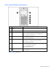
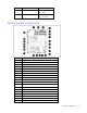
Item Description Status 1 NIC link LED On = Link Off = No link 2 NIC activity LED Flashing = Activity Off = No activity System board components Item Description 1 Processor power connector 2 Redundant power supply connector 3 System power connector 4 DIMM slot 4 (bank B) 5 DIMM slot 3 (bank A) 6 DIMM slot 2 (bank B) 7 DIMM slot 1 (bank A) 8 IDE connector 9 Front USB connector 10 Internal USB connector 11 SATA connector 12 System maintenance switch 13 Front panel LED boar
Item Description 20 PCI expansion slot 3 (PCI-X, 64-bit/100-MHz) 21 PCI expansion slot 4 (PCI Express x4**) 22 System fan connector 23 Optional serial port connector 24 Processor * x8 PCI Express cards are supported, but will run at x1 speeds. ** x8 PCI Express cards are supported, but will run at x4 speeds.
System board LEDs Item LED description Status 1 PPM error Amber = PPM has failed Off = Normal 2 DIMM 4 failure Amber = DIMM has failed or is missing Off = Normal 3 DIMM 3 failure Amber = DIMM has failed or is missing Off = Normal 4 DIMM 2 failure Amber = DIMM has failed or is missing Off = Normal 5 DIMM 1 failure Amber = DIMM has failed or is missing Off = Normal 6 Processor fault Amber = A multibit error has occurred Off = Normal 7 8 Hard drive cage fan failure Amber = Hard drive fa
Item LED description Status 11 Single bit error Amber = Single bit error limit has been exceeded Off = Normal 12 System fan failure Amber = System fan has failed Off = Normal System LEDs and internal health LED combinations When the internal health LED on the front panel illuminates either amber or red, the server is experiencing a health event. Combinations of illuminated system LEDs and the internal health LED indicate system status.
SAS and SATA device numbers Hot-plug SATA or SAS hard drive LEDs Item LED description Status 1 Fault/UID status Amber = Drive failure Flashing amber = Fault-process activity Blue = Unit identification is active Off = No fault-process activity 2 Online/Activity status Green = Drive activity Flashing green = High activity on the drive or drive is being configured as part of an array Off = No drive activity Component identification 14
The hard drive activity LED will not illuminate if using SATA drives connected to the embedded storage device. In this configuration, SATA hard drive activity can be identified using the LED on the system front panel. Fan locations NOTE: The air baffle and the processor heatsink are removed for clarity.
Operations In this section Power up the server ................................................................................................................................ 16 Power down the server............................................................................................................................ 16 Unlock the tower bezel ........................................................................................................................... 17 Remove the access panel ..........
Unlock the tower bezel The removable bezel must be unlocked and opened before accessing the hard drive cage and media bays. It must be unlocked before removing the access panel. The bezel must remain closed during normal server operations. If necessary, remove the bezel by lifting the open bezel from the chassis. Remove the access panel WARNING: To reduce the risk of personal injury from hot surfaces, allow the drives and the internal system components to cool before touching them.
4. Power up the server (on page 16).
Setup In this section Optional installation services ................................................................................................................... 19 Rack planning resources ......................................................................................................................... 20 Optimum environment............................................................................................................................. 20 Warnings and cautions......................
Rack planning resources The rack resource kit ships with all HP branded or Compaq branded 9000, 10000, and H9 series racks. For more information on the content of each resource, refer to the rack resource kit documentation. If you intend to deploy and configure multiple servers in a single rack, refer to the white paper on highdensity deployment at the HP website (http://www.hp.com/products/servers/platforms).
Temperature requirements To ensure continued safe and reliable equipment operation, install or position the system in a wellventilated, climate-controlled environment. The maximum recommended ambient operating temperature (TMRA) for most server products is 35°C (95°F). The temperature in the room where the rack is located must not exceed 35°C (95°F).
Warnings and cautions WARNING: To reduce the risk of personal injury or damage to the equipment, be sure that: • The leveling jacks are extended to the floor. • The full weight of the rack rests on the leveling jacks. • The stabilizing feet are attached to the rack if it is a single-rack installation. • The racks are coupled together in multiple-rack installations. • Only one component is extended at a time. A rack may become unstable if more than one component is extended for any reason.
The contents of the server shipping carton include: • Server • Power cord • Keyboard and mouse (not included in all configurations) • Hardware documentation, Documentation CD, and software media In addition to the supplied items, you may need: • Optional hard drives, array controllers, and tape drives • Operating system or application software • UPS or PDU Installing hardware options Install any hardware options before initializing the server.
Item Description 6 USB connectors (2) 7 RJ-45 Ethernet connector 8 RJ-45 connector (iLO 2) 9 Parallel connector 2. Connect the power cord to the rear of the server. 3. Connect the power cord to the AC power source. WARNING: To reduce the risk of electric shock or damage to the equipment: • Do not disable the power cord grounding plug. The grounding plug is an important safety feature. • Plug the power cord into a grounded (earthed) electrical outlet that is easily accessible at all times.
Hardware options installation In this section Introduction ........................................................................................................................................... 25 Memory ................................................................................................................................................ 25 Hard drives ...........................................................................................................................................
The following table lists some, but not all, possible configurations. For best performance, HP recommends dual-channel interleaved mode configurations.
Hot-plug SATA and hot-plug SAS hard drives can be used interchangeably when a SAS controller is installed. Before installing a SAS hard drive, you must install a SAS controller ("SAS controller" on page 28). A SATA controller is embedded for use with SATA drives only. CAUTION: To prevent improper cooling and thermal damage, do not operate the server unless all bays are populated with either a component or a blank. 1. Remove the bezel ("Unlock the tower bezel" on page 17). 2. Remove the hard drive blank.
4. Install the hard drive. 5. Determine the status of the hard drive from the hot-plug SAS hard drive LED combinations. 6. Install the bezel ("Unlock the tower bezel" on page 17). 7. Resume normal server operations. SAS controller 1. Power down the server (on page 16). 2. Remove the bezel ("Unlock the tower bezel" on page 17). 3. Remove the access panel (on page 17). 4. Remove the expansion slot cover ("Removing the expansion slot cover" on page 34). 5.
7. Install the access panel (on page 17). 8. Install the bezel ("Unlock the tower bezel" on page 17). 9. Power up the server (on page 16). DVD-ROM drive CAUTION: To prevent improper cooling and thermal damage, do not operate the server unless all bays are populated with either a component or a blank. 1. Power down the server (on page 16). 2. Remove the bezel ("Unlock the tower bezel" on page 17). 3. Remove the access panel (on page 17). 4.
8. Remove the applicable bezel blanks from the bezel. 9. Install the access panel (on page 17). 10. Install the bezel ("Unlock the tower bezel" on page 17). 11. Power up the server (on page 16). USB tape drive CAUTION: To prevent improper cooling and thermal damage, do not operate the server unless all bays are populated with either a component or a blank. 1. Power down the server (on page 16). 2. Remove the bezel ("Unlock the tower bezel" on page 17). 3. Remove the access panel (on page 17). 4.
5. Use a screwdriver to disengage the two wire supports inside the half-height drive bays. 6. Install the tape drive: a. Open the upper and lower wire retainers. b. Install the full-height tape drive. c. Close the upper and lower wire retainers.
7. Install the retaining screw. IMPORTANT: When installing a SCSI tape drive, an optional SCSI HBA controller is required. 8. Connect the data and power cables to the back of the tape drive. 9. Connect the data cable to the SCSI controller. 10. Remove the applicable bezel blanks from the bezel. 11. Install the bezel ("Unlock the tower bezel" on page 17). 12. Install the access panel (on page 17). 13. Power up the server (on page 16).
2. Remove the bezel ("Unlock the tower bezel" on page 17). 3. Remove the access panel (on page 17). 4. Remove the applicable media bay blank 5. Slide the diskette drive into the media drive bay. 6. Connect the diskette drive cable to the rear of the diskette drive and to the diskette drive cable connector on the system board ("System board components" on page 10). 7. Remove the applicable bezel blanks from the bezel. 8. Install the access panel (on page 17). 9.
Expansion boards The server supports PCI, PCI-X, and PCI Express expansion boards. Slot Expansion card type Connector Maximum speed 1 PCI Express x8 x1 2 PCI-X 64 bit, 3.3 V 100 MHz 3 PCI-X 64 bit, 3.3 V 100 MHz 4 PCI Express x8 x4 Removing the expansion slot cover 1. Power down the server (on page 16). 2. Remove the bezel ("Unlock the tower bezel" on page 17). 3. Remove the access panel (on page 17). 4. Remove the expansion slot cover.
5. Install the expansion board, and press firmly down to seat the board in the connector. 6. Connect any required internal or external cables to the expansion board. See the documentation that ships with the expansion board. 7. Install the access panel (on page 17). 8. Install the bezel ("Unlock the tower bezel" on page 17). 9. Power up the server (on page 16).
Cabling In this section SATA cabling ........................................................................................................................................ 36 SAS cabling .......................................................................................................................................... 37 SATA cabling NOTE: The hard drive fan cage is removed for clarity.
SAS cabling NOTE: The hard drive fan cage is removed for clarity.
Configuration and utilities In this section Configuration tools ................................................................................................................................. 38 Management tools.................................................................................................................................. 44 Diagnostic tools .....................................................................................................................................
Using SmartStart technology, the Scripting Toolkit provides a flexible way to create standard server configuration scripts. These scripts are used to automate many of the manual steps in the server configuration process. This automated server configuration process cuts time from each server deployed, making it possible to scale server deployments to high volumes in a rapid manner. For more information, and to download the SmartStart Scripting Toolkit, refer to the HP website (http://www.hp.
The auto-configuration process automatically runs when you boot the server for the first time. During the power-up sequence, the system ROM automatically configures the entire system without needing any intervention. During this process, the ORCA utility, in most cases, automatically configures the array to a default setting based on the number of drives connected to the server. NOTE: The server may not support all the following examples.
For optimum performance, the minimum display settings are 800 × 600 resolution and 256 colors. Servers running Microsoft® operating systems require Internet Explorer 5.5 (with Service Pack 1) or later. For Linux servers, refer to the README.TXT file for additional browser and support information. For more information, refer to the Configuring Arrays on HP Smart Array Controllers Reference Guide on the Documentation CD or the HP website (http://www.hp.com).
Configuring the software SATA RAID feature CAUTION: Back up any data stored on the hard drives before proceeding. The configuration process erases all data on the hard drives. 1. Power up the server (on page 16). 2. Press the F9 key to launch RBSU. NOTE: Enabling the RAID option in RBSU is only necessary for installation of the RAID driver. If this option is not enabled, the OS loads the standard ATA driver from the OS media. 3. Select Advanced Options>Embedded SATA RAID>Enable RAID. 4.
For more information on Software SATA RAID, see the HP Storage Manager HostRAID User Guide located on the Documentation CD. Option ROM Configuration for Arrays Before installing an operating system, you can use the ORCA utility to create the first logical drive, assign RAID levels, and establish online spare configurations.
Management tools Automatic Server Recovery ASR is a feature that causes the system to restart when a catastrophic operating system error occurs, such as a blue screen, ABEND, or panic. A system fail-safe timer, the ASR timer, starts when the System Management driver, also known as the Health Driver, is loaded. When the operating system is functioning properly, the system periodically resets the timer. However, when the operating system fails, the timer expires and restarts the server.
• Automatically checks for hardware, firmware, and operating system dependencies, and installs only the correct ROM upgrades required by each target server To download the tool and for more information, refer to the HP website (http://h18000.www1.hp.com/support/files/index.html). Erase Utility CAUTION: Perform a backup before running the System Erase Utility.
• DOS • Operating environments which do not provide native USB support For more information on ProLiant USB support, refer to the HP website (http://h18004.www1.hp.com/products/servers/platforms/usb-support.html). Internal USB functionality An internal USB connector is available for use with security key devices and USB drive keys.
Integrated Management Log The IML records hundreds of events and stores them in an easy-to-view form. The IML timestamps each event with 1-minute granularity.
If you do not use the SmartStart CD to install an operating system, drivers for some of the new hardware are required. These drivers, as well as other option drivers, ROM images, and value-add software can be downloaded from the HP website (http://www.hp.com/support). IMPORTANT: Always perform a backup before installing or updating device drivers.
Battery replacement If the server no longer automatically displays the correct date and time, you may need to replace the battery that provides power to the real-time clock. Under normal use, battery life is 5 to 10 years. WARNING: The computer contains an internal lithium manganese dioxide, a vanadium pentoxide, or an alkaline battery pack. A risk of fire and burns exists if the battery pack is not properly handled. To reduce the risk of personal injury: • Do not attempt to recharge the battery.
Troubleshooting In this section Troubleshooting resources ....................................................................................................................... 50 Pre-diagnostic steps ................................................................................................................................ 50 Loose connections .................................................................................................................................. 53 Service notifications.....
Important safety information Before servicing this product, read the Important Safety Information document provided with the server. Symbols on equipment The following symbols may be placed on equipment to indicate the presence of potentially hazardous conditions. This symbol indicates the presence of hazardous energy circuits or electric shock hazards. Refer all servicing to qualified personnel. WARNING: To reduce the risk of injury from electric shock hazards, do not open this enclosure.
WARNING: To reduce the risk of personal injury or damage to the equipment, be sure that: • The leveling feet are extended to the floor. • The full weight of the rack rests on the leveling feet. • The stabilizing feet are attached to the rack if it is a single-rack installation. • The racks are coupled together in multiple-rack installations. • Only one component is extended at a time. A rack may become unstable if more than one component is extended for any reason.
Prepare the server for diagnosis 1. Be sure the server is in the proper operating environment with adequate power, air conditioning, and humidity control. Refer to the server documentation for required environmental conditions. 2. Record any error messages displayed by the system. 3. Remove all diskettes and CDs from the media drives. 4. Power down the server and peripheral devices if you will be diagnosing the server offline. Always perform an orderly shutdown, if possible. This means you must: a.
Troubleshooting flowcharts To effectively troubleshoot a problem, HP recommends that you start with the first flowchart in this section, "Start diagnosis flowchart (on page 54)," and follow the appropriate diagnostic path. If the other flowcharts do not provide a troubleshooting solution, follow the diagnostic steps in "General diagnosis flowchart (on page 55).
General diagnosis flowchart The General diagnosis flowchart provides a generic approach to troubleshooting. If you are unsure of the problem, or if the other flowcharts do not fix the problem, use the following flowchart.
Item Refer to 4 The most recent version of a particular server or option firmware is available on the following websites: • HP Support website (http://www.hp.com/support) • HP ROM-BIOS/Firmware Updates website (http://h18023.www1.hp.com/support/files/server/us/romflash.ht ml) 5 "General memory problems are occurring" in the HP ProLiant Servers Troubleshooting Guide located on the Documentation CD or on the HP website (http://www.hp.
Server power-on problems flowchart Symptoms: • The server does not power on. • The system power LED is off or amber. • The external health LED is red or amber.
• The internal health LED is red or amber. NOTE: For the location of server LEDs and information on their statuses, refer to the server documentation.
Troubleshooting 59
POST problems flowchart Symptoms: • Server does not complete POST NOTE: The server has completed POST when the system attempts to access the boot device.
OS boot problems flowchart Symptoms: • Server does not boot a previously installed operating system • Server does not boot SmartStart Possible causes: • Corrupted operating system • Hard drive subsystem problem • Incorrect boot order setting in RBSU Troubleshooting 61
Item Refer to 1 HP ROM-Based Setup Utility User Guide (http://www.hp.com/servers/smartstart) 2 "POST problems flowchart (on page 60)" 3 • "Hard drive problems" in the HP ProLiant Servers Troubleshooting Guide located on the Documentation CD or on the HP website (http://www.hp.com/support) • Controller documentation 4 "HP Insight Diagnostics (on page 46)" or in the HP ProLiant Servers Troubleshooting Guide located on the Documentation CD or on the HP website (http://www.hp.
Server fault indications flowchart Symptoms: • Server boots, but a fault event is reported by Insight Management Agents (on page 45) • Server boots, but the internal health LED, external health LED, or component health LED is red or amber NOTE: For the location of server LEDs and information on their statuses, refer to the server documentation.
Possible causes: • Improperly seated or faulty internal or external component • Unsupported component installed • Redundancy failure • System overtemperature condition Item Refer to 1 "Management agents (on page 45)" or in the HP ProLiant Servers Troubleshooting Guide located on the Documentation CD or on the HP website (http://www.hp.
POST error messages and beep codes For a complete listing of error messages, refer to the "POST error messages" in the HP ProLiant Servers Troubleshooting Guide located on the Documentation CD or on the HP website (http://www.hp.com/support). WARNING: To avoid potential problems, ALWAYS read the warnings and cautionary information in the server documentation before removing, replacing, reseating, or modifying system components.
Regulatory compliance notices In this section Regulatory compliance identification numbers ........................................................................................... 66 Federal Communications Commission notice ............................................................................................. 66 Declaration of conformity for products marked with the FCC logo, United States only..................................... 67 Modifications...................................................
Class A equipment This equipment has been tested and found to comply with the limits for a Class A digital device, pursuant to Part 15 of the FCC Rules. These limits are designed to provide reasonable protection against harmful interference when the equipment is operated in a commercial environment. This equipment generates, uses, and can radiate radio frequency energy and, if not installed and used in accordance with the instructions, may cause harmful interference to radio communications.
Modifications The FCC requires the user to be notified that any changes or modifications made to this device that are not expressly approved by Hewlett-Packard Company may void the user’s authority to operate the equipment. Cables Connections to this device must be made with shielded cables with metallic RFI/EMI connector hoods in order to maintain compliance with FCC Rules and Regulations.
Disposal of waste equipment by users in private households in the European Union This symbol on the product or on its packaging indicates that this product must not be disposed of with your other household waste. Instead, it is your responsibility to dispose of your waste equipment by handing it over to a designated collection point for the recycling of waste electrical and electronic equipment.
Korean notice Class A equipment Class B equipment Laser compliance This product may be provided with an optical storage device (that is, CD or DVD drive) and/or fiber optic transceiver. Each of these devices contains a laser that is classified as a Class 1 Laser Product in accordance with US FDA regulations and the IEC 60825-1. The product does not emit hazardous laser radiation. Each laser product complies with 21 CFR 1040.10 and 1040.11 except for deviations pursuant to Laser Notice No.
• • • Do not attempt to recharge the battery. Do not expose the battery to temperatures higher than 60°C (140°F). Do not disassemble, crush, puncture, short external contacts, or dispose of in fire or water. Batteries, battery packs, and accumulators should not be disposed of together with the general household waste. To forward them to recycling or proper disposal, please use the public collection system or return them to HP, an authorized HP Partner, or their agents.
Electrostatic discharge In this section Preventing electrostatic discharge............................................................................................................. 72 Grounding methods to prevent electrostatic discharge ................................................................................ 72 Preventing electrostatic discharge To prevent damaging the system, be aware of the precautions you need to follow when setting up the system or handling parts.
Specifications In this section Environmental specifications .................................................................................................................... 73 Server specifications ...............................................................................................................................
Specification Value Rated steady-state power 3.3 V/5 V 110 W 12 V CPU 300W Maximum peak power 410 W (non-redundant non-hotplug) 430 W (redundant hot-plug) * 100 to 127 VAC is required for 8 A; 200 to 240 VAC is required for 4 A.
Technical support In this section Related documents ................................................................................................................................. 75 HP contact information............................................................................................................................ 75 Customer Self Repair ..............................................................................................................................
Based on availability and where geography permits, CSR parts will be shipped for next business day delivery. Same day or four-hour delivery may be offered at an additional charge where geography permits. If assistance is required, you can call the HP Technical Support Center and a technician will help you over the telephone. HP specifies in the materials shipped with a replacement CSR part whether a defective part must be returned to HP.
assistenza HP) identifica il guasto come riparabile mediante un ricambio CSR, HP lo spedirà direttamente al cliente per la sostituzione. Vi sono due categorie di parti CSR: • Obbligatorie – Parti che devono essere necessariamente riparate dal cliente. Se il cliente ne affida la riparazione ad HP, deve sostenere le spese di spedizione e di manodopera per il servizio. • Opzionali – Parti la cui riparazione da parte del cliente è facoltativa. Si tratta comunque di componenti progettati per questo scopo.
stellen. Im Falle von Customer Self Repair kommt HP für alle Kosten für die Lieferung und Rücksendung auf und bestimmt den Kurier-/Frachtdienst. Weitere Informationen über das HP Customer Self Repair Programm erhalten Sie von Ihrem Servicepartner vor Ort. Informationen über das CSR-Programm in Nordamerika finden Sie auf der HP Website unter (http://www.hp.com/go/selfrepair).
• Verplicht: Onderdelen waarvoor reparatie door de klant verplicht is. Als u HP verzoekt deze onderdelen voor u te vervangen, worden u voor deze service reiskosten en arbeidsloon in rekening gebracht. • Optioneel: Onderdelen waarvoor reparatie door de klant optioneel is. Ook deze onderdelen zijn ontworpen voor reparatie door de klant.
Para obter mais informações sobre o programa de reparo feito pelo cliente da HP, entre em contato com o fornecedor de serviços local. Para o programa norte-americano, visite o site da HP (http://www.hp.com/go/selfrepair).
Technical support 81
Technical support 82
Acronyms and abbreviations ABEND abnormal end ACU Array Configuration Utility ASR Automatic Server Recovery DDR double data rate DIMM dual inline memory module ECC error checking and correcting HBA host bus adapter IEC International Electrotechnical Commission iLO Integrated Lights-Out IML Integrated Management Log IPL initial program load IRQ interrupt request Acronyms and abbreviations 83
LDAP Lightweight Directory Access Protocol MPS multi-processor specification NEMA National Electrical Manufacturers Association NFPA National Fire Protection Association NIC network interface controller NMI non-maskable interrupt NVRAM non-volatile memory PCI-X peripheral component interconnect extended PDU power distribution unit POST Power-On Self Test PPM processor power module PSP ProLiant Support Pack PXE Preboot Execution Environment RAID redundant array of inexpensive (or independent) di
RBSU ROM-Based Setup Utility RDP Rapid Deployment Pack SAS serial attached SCSI SATA serial ATA SDRAM synchronous dynamic RAM SIM Systems Insight Manager TMRA recommended ambient operating temperature UID unit identification UPS uninterruptible power system USB universal serial bus VHDCI very high density cable interconnect WOL Wake-on LAN Acronyms and abbreviations 85
Index A D AC power supply 9 access panel 17 ACU (Array Configuration Utility) 40 additional information 75 ADU (Array Diagnostic Utility) 46 airflow requirements 20, 21 Altiris Deployment Solution 43 Altiris eXpress Deployment Server 43 Array Configuration Utility (ACU) 40 Array Diagnostic Utility (ADU) 46 ASR (Automatic Server Recovery) 44 authorized reseller 75 Automatic Server Recovery (ASR) 44 Autorun menu 38 deployment software 43 diagnosing problems 50, 53 diagnostic tools 38, 43, 44, 46 diagnostic
H hard drive LEDs 14 hard drives 26 hardware options 25 hardware options installation 23, 25 health driver 44 help resources 75 HP Insight Diagnostics 46 HP Management Packs 1.
problem diagnosis 50 processor failure LEDs 11 ProLiant Support Pack (PSP) 48 PSPs, overview 48 R rack installation 19 rack resources 20 rack stability 51 rack warnings 51 rear panel buttons 9 rear panel connectors 8 rear panel LEDs 9 registering the server 24 regulatory compliance identification numbers 66 regulatory compliance notices 66, 68, 69, 71 Resource Paqs 48 RJ-45 network connector LEDs 9 ROM, updating 44 ROMPaq utility 44 S safety considerations 50 SAS cabling 37 SAS connector 28 SAS device num