HP ProLiant ML100 Series Server User Guide for HP ProLiant ML110 G6 and HP ProLiant ML150 G6 Servers Abstract This document is for the person who installs, administers, and troubleshoots servers and storage systems. HP assumes you are qualified in the servicing of computer equipment and trained in recognizing hazards in products with hazardous energy levels.
© Copyright 2009, 2012 Hewlett-Packard Development Company, L.P. The information contained herein is subject to change without notice. The only warranties for HP products and services are set forth in the express warranty statements accompanying such products and services. Nothing herein should be construed as constituting an additional warranty. HP shall not be liable for technical or editorial errors or omissions contained herein. Microsoft, Windows, and Windows Server are U.S.
Contents Operations................................................................................................................................... 7 Power up the server ...................................................................................................................................... 7 Power down the server ................................................................................................................................. 7 Remove the access panel ........................
Retaining the recovery key/password................................................................................................. 37 Enabling the Trusted Platform Module ................................................................................................. 37 Software and configuration utilities ............................................................................................... 38 ROM-Based Setup Utility .............................................................................
System open circuits and short circuits ................................................................................................ 72 External device problems .................................................................................................................. 72 Audio problems ............................................................................................................................... 73 Printer problems ..................................................................
Before you contact HP ................................................................................................................................ 95 Customer Self Repair .................................................................................................................................. 95 Acronyms and abbreviations ...................................................................................................... 103 Documentation feedback .............................................
Operations Power up the server To power up the server, press the Power On/Standby button. Power down the server WARNING: To reduce the risk of personal injury, electric shock, or damage to the equipment, remove the power cord to remove power from the server. The front panel Power On/Standby button does not completely shut off system power. Portions of the power supply and some internal circuitry remain active until AC power is removed.
Remove the tower bezel (ML110 G6 servers) 1. Remove the access panel (on page 7). 2. To release the bezel, push the left side of the bezel. 3. Release the tabs, then turn the bezel counter-clockwise to remove it. To replace the component, reverse the removal procedure. For server-specific information, see the installation sheet that ships with the server. Remove the tower bezel (ML150 G6 servers) 1. Insert the key provided with the server and turn clockwise to unlock the bezel.
Setup Optional installation services Delivered by experienced, certified engineers, HP Care Pack services help you keep your servers up and running with support packages tailored specifically for HP ProLiant systems. HP Care Packs let you integrate both hardware and software support into a single package. A number of service level options are available to meet your needs.
In a tower configuration, leave at least a 7.6-cm (3.0-in) clearance space at the front and back of the server for proper ventilation. Rack server To allow for servicing and adequate airflow, observe the following space and airflow requirements when deciding where to install a rack: • Leave a minimum clearance of 63.5 cm (25 in) in front of the rack. • Leave a minimum clearance of 76.2 cm (30 in) behind the rack. • Leave a minimum clearance of 121.
CAUTION: To reduce the risk of damage to the equipment when installing third-party options: • Do not permit optional equipment to impede airflow around the server or to increase the internal rack temperature beyond the maximum allowable limits. • Do not exceed the manufacturer’s TMRA. Power requirements Installation of this equipment must comply with local and regional electrical regulations governing the installation of information technology equipment by licensed electricians.
Rack warnings WARNING: To reduce the risk of personal injury or damage to the equipment, be sure that: • • • • • The leveling jacks are extended to the floor. The full weight of the rack rests on the leveling jacks. The stabilizing feet are attached to the rack if it is a single-rack installation. The racks are coupled together in multiple-rack installations. Only one component is extended at a time. A rack may become unstable if more than one component is extended for any reason.
Hardware options installation Introduction If more than one option is being installed, read the installation instructions for all the hardware options and identify similar steps to streamline the installation process. WARNING: To reduce the risk of personal injury from hot surfaces, allow the drives and the internal system components to cool before touching them. CAUTION: To prevent damage to electrical components, properly ground the server before beginning any installation procedure.
5. Open the processor locking lever and the processor socket retaining bracket. Do not remove the processor socket cover. IMPORTANT: Be sure the processor remains inside the processor installation tool. 6. If the processor has separated from the installation tool, carefully re-insert the processor in the tool. Handle the processor by the edges only, and do not touch the bottom of the processor, especially the contact area.
7. Align the processor installation tool with the socket, and then install the processor. THE PINS ON THE SYSTEM BOARD ARE VERY FRAGILE AND EASILY DAMAGED. CAUTION: THE PINS ON THE SYSTEM BOARD ARE VERY FRAGILE AND EASILY DAMAGED. To avoid damage to the system board: • Never install or remove a processor without using the processor installation tool. • Do not touch the processor socket contacts. • Do not tilt or slide the processor when lowering the processor into the socket.
8. Press the tabs on the processor installation tool to separate it from the processor, and then remove the tool. 9. Close the processor socket retaining bracket and the processor locking lever. The processor socket cover is automatically ejected. Remove the cover. CAUTION: Be sure to close the processor socket retaining bracket before closing the processor locking lever. The lever should close without resistance.
13. 14. For ML150 G6 Servers, do one of the following: o Close or install the tower bezel, as needed. o Slide the server back into the rack. Power up the server (on page 7). SAS and SATA_hard drive options The HP ProLiant ML150 G6 Server supports up to eight hard drives: • SATA hard drives only with the embedded SATA controller • SAS or SATA hard drives with an optional SAS controller For optimal performance, avoid mixing SAS and SATA hard drives.
Removable media device option (ML110 G6 servers) This process only represents one installation method. For instructions for installing the media device into a specific server, see the installation sheet that ships with the server or the HP website (http://www.hp.com/go/bizsupport). To install the component: 1. Power down the server (on page 7). 2. Extend the server from the rack. 3. Remove the access panel (on page 7). 4. Remove the tower bezel ("Remove the tower bezel (ML110 G6 servers)" on page 8).
8. Connect the data and power cables. 9. Connect the cables to the system board or to an expansion board, as directed by the option documentation. 10. Slide the server back into the rack. 11. Install the access panel. 12. Install the tower bezel. 13. Power up the server (on page 7). Removable media device option (ML150 G6 servers) This process represents only one installation method.
4. Press the fan holder release tab, and then remove the fan holder. 5. Remove the bezel blank. HP recommends that you remove all bezel blanks to facilitate drive installation. 6. Slide the media device part of the way into the bay. 7. Connect the SATA power cable to the media drive. 8. Connect the device cable to the device and the system board or to an expansion board, as directed by the option documentation. 9. Slide the media drive fully into the bay until it is seated securely. 10.
13. Power up the server (on page 7). Memory options (ML110 G6 servers) The memory subsystem in this server supports UDIMMs. In this section, the term "DIMM" is used. When specified as UDIMM, the information applies to that type only. All memory installed in the server must be the same type.
IMPORTANT: This server does not support mixing RDIMMs and UDIMMs. Attempting to mix these two types causes the server to halt during BIOS initialization. The memory subsystem may be populated with either RDIMMs or UDIMMs, but mixing the two types is not supported. To determine DIMM characteristics, use the label attached to the DIMM and the following illustration and table.
• Two DIMMs (interleaving) install in slot 2 and slot 4 for optimal performance. Memory options (ML150 G6 servers) IMPORTANT: This server does not support mixing RDIMMs and UDIMMs. Attempting to mix these two types causes the server to halt during BIOS initialization. The memory subsystem in this server can support RDIMMs or UDIMMs. Both types are referred to as DIMMs when the information applies to both types. When specified as RDIMM or UDIMM, the information applies to that type only.
Dual- and quad-rank DIMMs provide the greatest capacity with the existing memory technology. For example, if current DRAM technology supports 2-GB single-rank DIMMs, a dual-rank DIMM would be 4-GB, and a quad-rank DIMM would be 8-GB. DIMM identification IMPORTANT: This server does not support mixing RDIMMs and UDIMMs. Attempting to mix these two types causes the server to halt during BIOS initialization.
Advanced Memory Protection options are configured in RBSU. If the requested AMP mode is not supported by the installed DIMM configuration, the server boots in Advanced ECC mode. For more information, see "HP ROM-Based Setup Utility ("ROM-Based Setup Utility" on page 38)." For the latest memory configuration information, see the QuickSpecs on the HP website (http://www.hp.com). RDIMM maximum memory configurations The following table lists the maximum memory configuration possible with 4-GB RDIMMs.
Populated slots (per channel) Rank Speeds supported (MHz) 1 Single- or dual-rank 800, 1333, 1066 1 Quad-rank 800, 1066 2 Single- or dual-rank 800, 1066 2 Single-, dual-, or quad-rank 800 Advanced ECC population guidelines For Advanced ECC mode configurations, observe the following guidelines: • Observe the general DIMM slot population guidelines (on page 25). • DIMMs may be installed individually.
o HP ProLiant ML110 G6 server o HP ProLiant ML150 G6 server CAUTION: To prevent improper cooling and thermal damage, do not operate the server unless all PCI slots have either an expansion slot cover or an expansion board installed.
6. Remove the expansion slot cover. IMPORTANT: It may be necessary to remove the slot cover next to the slot in which you are installing a board. 7. Install the expansion board. 8. Close the slot cover retainer. 9. Connect any required internal cables to the expansion board. For more information, see the documentation that ships with the expansion board. 10. Install the access panel. 11. For ML110 G6 servers, slide the server back into the rack. 12.
13. Connect any required external cables to the expansion board. 14. Power up the server (on page 7). Installing a storage controller IMPORTANT: For additional installation and configuration information, refer to the documentation that ships with the option. To install the component: 1. Power down the server (on page 7). 2. For ML110 G6 servers, extend the server from the rack. 3.
1. Power down the server (on page 7). 2. For ML110 G6 servers, extend the server from the rack. 3. For ML150 G6 servers, do one of the following: o Unlock and remove the bezel ("Remove the tower bezel (ML150 G6 servers)" on page 8). o Extend the server from the rack. 4. Remove the access panel (on page 7). 5. Remove the air baffle. For more information, see the server installation sheet on the HP website (http://www.hp.com/go/bizsupport). 6. Open the DIMM slot latches. 7. Install the DIMM.
CAUTION: After the server is powered down, wait 15 seconds and then check the amber LED before unplugging the cable from the cache module. If the amber LED blinks after 15 seconds, do not remove the cable from the cache module. The cache module is backing up data, and data is lost if the cable is detached. IMPORTANT: The battery pack might have a low charge when installed. In this case, a POST error message is displayed when the server is powered up, indicating that the battery pack is temporarily disabled.
7. Connect the cable to the cache module. 8. Install the battery pack. 9. Connect the cable to the controller. 10. Route the cable. 11. Install the access panel. 12. For ML110 G6 servers, slide the server back into the rack. 13. For ML150 G6 servers, do one of the following: o Close or install the tower bezel, as needed. o Slide the server back into the rack. 14. Install the server into the rack. 15. Power up the server (on page 7).
Installing the FBWC module and capacitor pack To install the component: CAUTION: The cache module connector does not use the industry standard DDR3 mini DIMM pinout. Do not use this controller with cache modules designed for other controller models, because the controller can malfunction and you can lose data. Also, do not transfer this cache module to an unsupported controller model, because you can lose data. 1. Back up all data. 2. Close all applications. 3. Power down the server (on page 7).
9. Install the cache module. 10. Install the capacitor pack. 11. Route the cable. 12. Install the access panel. 13. For ML110 G6 Servers, slide the server back into the rack. 14. For ML150 G6 Servers, do one of the following: 15. o Close or install the tower bezel, as needed. o Slide the server into the rack. Power up the server (on page 7). HP Trusted Platform Module option Use these instructions to install and enable a TPM on a supported server. This procedure includes three sections: 1.
2. Retaining the recovery key/password (on page 37). 3. Enabling the Trusted Platform Module (on page 37). Enabling the TPM requires accessing RBSU ("ROM-Based Setup Utility" on page 38). For more information about RBSU, see the HP website (http://www.hp.com/go/ilomgmtengine/docs). TPM installation requires the use of drive encryption technology, such as the Microsoft Windows BitLocker Drive Encryption feature. For more information on BitLocker, see the Microsoft website (http://www.microsoft.com).
CAUTION: Any attempt to remove an installed TPM from the system board breaks or disfigures the TPM security rivet. Upon locating a broken or disfigured rivet on an installed TPM, administrators should consider the system compromised and take appropriate measures to ensure the integrity of the system data. 7. Install the TPM board. Press down on the connector to seat the board. 8. Install the TPM security rivet by pressing the rivet firmly into the system board. 9. Install the access panel. 10.
Retaining the recovery key/password The recovery key/password is generated during BitLocker™ setup, and can be saved and printed after BitLocker™ is enabled. When using BitLocker™, always retain the recovery key/password. The recovery key/password is required to enter Recovery Mode after BitLocker™ detects a possible compromise of system integrity.
Software and configuration utilities ROM-Based Setup Utility RBSU, an embedded configuration utility, performs a wide range of configuration activities that may include: • Configuring system devices and installed options • Displaying system information • Selecting the primary boot controller • Configuring memory options For more information on RBSU, see the HP ROM-Based Setup Utility User Guide on the Documentation CD or the HP website (http://www.hp.com/support/smartstart/documentation).
NOTE: If the boot drive is not empty or has been written to in the past, ORCA does not automatically configure the array. You must run ORCA to configure the array settings. Drive configuration RAID function (smart array controller) RAID function (software) 2 0 or 1 0 or 1 3 5 — 4 6 or 10 10 6 50 — 8 60 — To change any ORCA default settings and override the auto-configuration process, press the F8 key when prompted.
• Remains available any time that the server is on • Displays on-screen tips for individual steps of a configuration procedure • Beginning with ACU version 8.28.13.0, provides diagnostic functionality on the Diagnostics tab (formerly known as Array Diagnostics Utility). For optimum performance, the minimum display settings are 1024 × 768 resolution and 16-bit color. Servers running Microsoft® operating systems require one of the following supported browsers: • Internet Explorer 6.
Management tools ROMPaq utility The ROMPaq utility enables you to upgrade the system firmware (BIOS). To upgrade the firmware, insert a ROMPaq USB Key into an available USB port and boot the system. In addition to ROMPaq, Online Flash Components for Windows and Linux operating systems are available for updating the system firmware. The ROMPaq utility checks the system and provides a choice (if more than one exists) of available firmware revisions.
Legacy USB support provides USB functionality in environments where USB support is not available normally.
IMPORTANT: Always perform a backup before installing or updating device drivers. Operating System Version Support For information about specific versions of a supported operating system, refer to the operating system support matrix (http://www.hp.com/go/supportos). Subscriber's choice HP's Subscriber's Choice is a customizable subscription sign-up service that customers use to receive personalized email product tips, feature articles, driver and support alerts, or other notifications.
Creating a RAID volume 1. Enable SATA RAID functionality in RBSU ("Enabling the SATA RAID feature in RBSU" on page 43). 2. After the system reboots, press F8 to activate the RAID Configuration Utility. 3. From the Option menu, select Array Configuration Utility. 4. Verify that two SATA drives are installed. 5. In the Main menu screen, select Create Array from the main menu. The system prompts a selection of RAID 0, RAID 1, or RAID 10. 6. Select a RAID level.
USB diskette and CD-ROM drives For driver installation purposes, a USB diskette drive and USB CD-ROM drive are sufficient, unless otherwise indicated in driver-specific documentation. NOTE: Do not use a USB drive key in place of the diskette drive. The OS does not support driver installation from a USB drive key. NOTE: HP recommends the use of HP standard USB disk drives. HP provides both standard USB 2.0 support and legacy USB 2.0 support.
IMPORTANT: The LO100i option kit is required to use the Virtual Floppy feature. For more information, see the HP ProLiant Lights-Out Remote Management User Guide on the HP website (http://h20000.www2.hp.com/bizsupport/TechSupport/Home.jsp). 1. Ensure that a network cable is connected to the LO100 NIC port on the rear of the server. 2. Boot the server, and then press F10 to enter the ROM-Based Setup Utility (RBSU). 3. Enable the Embedded SATA RAID option under the Advanced Options section. 4.
Troubleshooting Pre-diagnostic steps WARNING: To avoid potential problems, ALWAYS read the warnings and cautionary information in the server documentation before removing, replacing, reseating, or modifying system components. IMPORTANT: This guide provides information for multiple servers. Some information may not apply to the server you are troubleshooting. Refer to the server documentation for information on procedures, hardware options, software tools, and operating systems supported by the server. 1.
This symbol indicates the presence of a hot surface or hot component. If this surface is contacted, the potential for injury exists. WARNING: To reduce the risk of injury from a hot component, allow the surface to cool before touching. 20.41-27.22 kg 47.18-60 lb This symbol indicates that the component exceeds the recommended weight for one individual to handle safely.
WARNING: To reduce the risk of personal injury or damage to the equipment: 20.41-27.22 kg 47.18-60 lb • Observe local occupation health and safety requirements and guidelines for manual handling. • Obtain adequate assistance to lift and stabilize the chassis during installation or removal. • The server is unstable when not fastened to the rails. • When mounting the server in a rack, remove the power supplies and any other removable module to reduce the overall weight of the product.
6. Collect all tools and utilities, such as a Torx screwdriver, loopback adapters, ESD wrist strap, and software utilities, necessary to troubleshoot the problem. HP recommends you have access to the server documentation for server-specific information.
HP offers a subscription service that can provide notification of firmware updates. For more information, see "Subscriber's Choice (on page 43)." For detailed information on updating firmware, see "Firmware maintenance (on page 80)." DIMM handling guidelines CAUTION: Failure to properly handle DIMMs can cause damage to DIMM components and the system board connector. When handling a DIMM, observe the following guidelines: • Avoid electrostatic discharge (on page 94).
Online/activity LED (green) Fault/UID LED (amber/blue) Interpretation On, off, or flashing Alternating amber and blue The drive has failed, or a predictive failure alert has been received for this drive; it also has been selected by a management application. On, off, or flashing Steadily blue The drive is operating normally, and it has been selected by a management application. On Amber, flashing regularly (1 Hz) A predictive failure alert has been received for this drive.
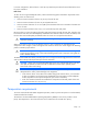
Start diagnosis flowchart Use the following flowchart and table to start the diagnostic process. Item See 1 "General diagnosis flowchart (on page 53)" 2 "Power-on problems flowchart (on page 55)" 3 "POST problems flowchart (on page 57)" 4 "OS boot problems flowchart (on page 59)" 5 "Server fault indications flowchart (on page 60)" General diagnosis flowchart The General Diagnosis flowchart provides a generic approach to troubleshooting.
Item See 4 The most recent version of a particular server or option firmware is available on the HP website (http://www.hp.com/support). 5 "General memory problems are occurring (on page 70)" 6 • • • 7 • Server maintenance and service guide, located on the Easy Set-up CD or the HP website (http://www.hp.com/products/servers/platforms) "Hardware problems (on page 61)" Server maintenance and service guide, located on the Easy Set-up CD or the HP website (http://www.hp.
Power-on problems flowchart Symptoms: • The server does not power on. • The system power LED is off or amber.
NOTE: For the location of server LEDs and information on their statuses, refer to the server documentation. Possible causes: • Improperly seated or faulty power supply • Loose or faulty power cord • Power source problem • Power on circuit problem • Improperly seated component or interlock problem • Faulty internal component Item See 1 Server maintenance and service guide, located on the Easy Set-up CD or the HP website (http://www.hp.
POST problems flowchart Symptoms: • Server does not complete POST NOTE: The server has completed POST when the system attempts to access the boot device.
Item See 1 Server maintenance and service guide, located on the Easy Set-up CD or the HP website (http://www.hp.com/products/servers/platforms) 2 "Loose connections (on page 50)" 3 "General memory problems are occurring (on page 70)" 4 • • 5 "Symptom information (on page 49)" 6 • • 7 "HP contact information (on page 95)" "Hardware problems (on page 61)" Server maintenance and service guide, located on the Easy Set-up CD or the HP website (http://www.hp.
OS boot problems flowchart Symptom: Server does not boot a previously installed operating system.
Server fault indications flowchart Symptom: Server boots, but the internal health LED or external health LED is red or amber. NOTE: For the location of server LEDs and information on their statuses, refer to the server documentation.
• System overtemperature condition Item See 1 Server maintenance and service guide, located on the Easy Set-up CD or the HP website (http://www.hp.com/products/servers/platforms) 2 "Power-on problems flowchart (on page 55)" 3 "HP Insight Diagnostics (on page 40)" 4 • • 5 "HP contact information (on page 95)" "Hardware problems (on page 61)" Server maintenance and service guide, located on the Easy Set-up CD or the HP website (http://www.hp.
Internal system problems (on page 66) System open circuits and short circuits (on page 72) External device problems (on page 72) Audio problems (on page 73) Printer problems (on page 74) Mouse and keyboard problems (on page 74) Modem problems (on page 74) Network controller problems (on page 76) Power problems Power source problems Action: 1. Press the Power On/Standby button to be sure it is on.
UPS problems UPS is not working properly Action: 1. Be sure the UPS batteries are charged to the proper level for operation. See the UPS documentation for details. 2. Be sure the UPS power switch is in the On position. See the UPS documentation for the location of the switch. 3. Be sure the UPS software is updated to the latest version. Use the Power Management software located on the Power Management CD. 4.
2. Refer to the release notes included with the hardware to be sure the problem is not caused by a last minute change to the hardware release. If no documentation is available, refer to the HP support website (http://www.hp.com/support). 3. Be sure the new hardware is installed properly. Refer to the device, server, and operating system documentation to be sure all requirements are met.
CAUTION: Only authorized technicians trained by HP should attempt to remove the system board. If you believe the system board requires replacement, contact HP Technical Support ("HP contact information" on page 95) before proceeding. o If the system fails in this minimum configuration, one of the primary components has failed. If you have already verified that the processor, PPM, power supply, and memory are working before getting to this point, replace the system board.
Internal system problems CD-ROM and DVD drive problems System does not boot from the drive Action: 1. Be sure the drive boot order is set so that the server boots from the CD-ROM drive first. 2. If the CD-ROM drive jumpers are set to CS (the factory default), be sure the CD-ROM drive is installed as device 0 on the cable so that it is in position for the server to boot from the drive. 3. Be sure no loose connections (on page 50) exist. 4.
DAT drives require cleaning every 8 to 25 hours of use or they may fail intermittently when using marginal or bad media. Be sure you are following the proper cleaning procedures described in the device and server documentation. NOTE: New DAT tapes may contain debris that will contaminate the DAT drive read/write head. If using new tapes for backup, clean the DAT drive frequently.
2. Check for and disconnect any non-bootable USB devices. Diskette drive cannot write to a diskette Action: 1. If the diskette is not formatted, format the diskette. 2. Be sure the diskette is not write protected. If it is, use another diskette or remove the write protection. 3. Be sure you are attempting to write to the proper drive by checking the drive letter in the path statement. 4. Be sure enough space is available on the diskette. Fan problems General fan problems are occurring Action: 1.
No hard drives are recognized Action: 1. Be sure no power problems (on page 62) exist. 2. Check for loose connections (on page 50). 3. Be sure that the controller supports the hard drives being installed. 4. Be sure the controller has the most recent firmware. 5. If the controller supports license keys and the configuration is dual domain, be sure the license key is installed. Hard drive is not recognized by the server Action: 1.
Server response time is slower than usual Action: Be sure the hard drive is not full, and increase the amount of free space on the hard drive, if needed. It is recommended that hard drives should have a minimum of 15 percent free space. Memory problems General memory problems are occurring Action: • • Isolate and minimize the memory configuration. Use care when handling DIMMs ("DIMM handling guidelines" on page 51).
Server fails to recognize existing memory Action: 1. Reseat the memory. Use care when handling DIMMs ("DIMM handling guidelines" on page 51). 2. Be sure the memory is configured properly. See the server documentation. 3. Be sure a memory count error did not occur ("Memory count error exists" on page 70). See the message displaying memory count during POST. Server fails to recognize new memory Action: 1.
CAUTION: Removal of some processors and heatsinks require special considerations for replacement, while other processors and heatsinks are integrated and cannot be reused once separated. For specific instructions for the server you are troubleshooting, refer to processor information in the server user guide. 5. If the server has only one processor installed, replace it with a known functional processor. If the problem is resolved after you restart the server, the original processor failed. 6.
1. Power up the monitor and be sure the monitor light is on, indicating that the monitor is receiving power. 2. Be sure the monitor power cord is plugged into a working grounded (earthed) AC outlet. 3. Be sure the monitor is cabled to the intended server or KVM connection. 4. Be sure no loose connections (on page 50) exist. o For rack-mounted servers, check the cables to the KVM switch and be sure the switch is correctly set for the server.
Printer problems Printer does not print Action: 1. Be sure the printer is powered up and online. 2. Be sure no loose connections (on page 50) exist. 3. Be sure the correct printer drivers are installed. Printer output is garbled Action: Be sure the correct printer drivers are installed. Mouse and keyboard problems Action: 1. Be sure no loose connections (on page 50) exist. If a KVM switching device is in use, be sure the server is properly connected to the switch.
No response occurs when you type AT commands Action: Reconfigure the COM port address for the modem. 1. Be sure the communications software is set to the COM port to which the modem is connected. 2. Check IRQ settings in the software and on the modem to be sure no conflict exists. 3. Type AT&F at the command prompt to reset the modem to factory-default settings. 4. Be sure you are in terminal mode and not MS-DOS mode. 5. Refer to the HP website (http://www.hp.
2. Be sure no line interference exists. Retry the connection by dialing the number several times. If conditions remain poor, contact the telephone company to have the line tested. 3. Be sure an incoming call is not breaking the connection due to call waiting. Disable call waiting, and then reestablish the connection. AT command initialization string is not working Action: Use the most basic string possible to perform the task. The default initialization string is AT&F&C1&D2&K3.
3. Be sure the network cable is working by replacing it with a known functional cable. 4. Be sure a software problem has not caused failure. Refer to the operating system documentation for guidelines on adding or replacing PCI Hot Plug devices, if applicable. 5. Be sure the server and operating system support the controller. Refer to the server and operating system documentation. 6. Be sure the controller is enabled in the BIOS Setup Utility. 7.
Problems are occurring with the network interconnect blades Action: Be sure the network interconnect blades are properly seated and connected. Software problems The best sources of information for software problems are the operating system and application software documentation, which may also point to fault detection tools that report errors and preserve the system configuration. Other useful resources include HP Insight Diagnostics (on page 40) and HP SIM.
Operating system updates Use care when applying operating system updates (Service Packs, hotfixes, and patches). Before updating the operating system, read the release notes for each update. If you do not require specific fixes from the update, it is recommended that you do not apply the updates. Some updates overwrite files specific to HP. If you decide to apply an operating system update: 1. Perform a full system backup. 2. Apply the operating system update, using the instructions provided. 3.
Linux operating systems For troubleshooting information specific to Linux operating systems, refer to the Linux for ProLiant website (http://h18000.www1.hp.com/products/servers/linux). Application software problems Software locks up Action: 1. Check the application log and operating system log for entries indicating why the software failed. 2. Check for incompatibility with other software on the server. 3. Check the support website of the software vendor for known problems. 4.
The process of updating system or option firmware is referred to as a flash process or flashing the ROM. A firmware or ROM flash removes the existing version of firmware from the ROM and replaces it with a more recent version. Update the firmware to do the following: • Support new hardware, such as a processor revision • Support new features • Correct problems in a previous firmware version Without the correct firmware version, the server and hardware options may not function properly.
To flash the ROM using ROMPaq: 1. Download the system ROMPaq utility diskette or USB drive key for each target server. ROMPaq downloads are available on the HP website (http://www.hp.com/support). 2. Shut down each target server, and then reboot using the correct ROMPaq diskette or USB drive key for that server. 3. Follow the interactive session in the ROMPaq utility, and then select the devices to be flashed. 4.
Contacting HP Contacting HP technical support or an authorized reseller (on page 83) Server information you need Operating system information you need (on page 84) Contacting HP technical support or an authorized reseller Before contacting HP, always attempt to resolve problems by completing the procedures in this guide. IMPORTANT: Collect the appropriate server information and operating system information ("Operating system information you need" on page 84) before contacting HP for support.
• • Specific software information: o Operating system information ("Operating system information you need" on page 84) o List of third-party, HP, and Compaq software installed o PCAnywhere information, if installed o Verification of latest drivers installed o Verification of latest ROM/BIOS o Verification of latest firmware on array controllers and drives Results from attempts to clear NVRAM Operating system information you need Depending on the problem, you may be asked for certain pieces of
Linux operating systems Collect the following information: • Operating system distribution and version Look for a file named /etc/distribution-release (for example, /etc/redhat-release) • Kernel version in use • Output from the following commands (performed by root): • • o lspci -v o uname -a o cat /proc/meminfo o cat /proc/cpuinfo o rpm -ga o dmesg o lsmod o ps -ef o ifconfig -a o chkconfig -list o mount Contents of the following files: o /var/log/messages o /etc/modules.
Battery If the server no longer automatically displays the correct date and time, you may need to replace the battery that provides power to the real-time clock. Under normal use, battery life is 5 to 10 years. WARNING: The computer contains an internal lithium manganese dioxide, a vanadium pentoxide, or an alkaline battery pack. A risk of fire and burns exists if the battery pack is not properly handled. To reduce the risk of personal injury: • • • • Do not attempt to recharge the battery.
To replace the component, reverse the removal procedure. For more information about battery replacement or proper disposal, contact an authorized reseller or an authorized service provider.
Regulatory compliance notices Regulatory compliance identification numbers For the purpose of regulatory compliance certifications and identification, this product has been assigned a unique regulatory model number. The regulatory model number can be found on the product nameplate label, along with all required approval markings and information. When requesting compliance information for this product, always refer to this regulatory model number.
radio communications. However, there is no guarantee that interference will not occur in a particular installation. If this equipment does cause harmful interference to radio or television reception, which can be determined by turning the equipment off and on, the user is encouraged to try to correct the interference by one or more of the following measures: • Reorient or relocate the receiving antenna. • Increase the separation between the equipment and receiver.
This Class A digital apparatus meets all requirements of the Canadian Interference-Causing Equipment Regulations. Cet appareil numérique de la classe A respecte toutes les exigences du Règlement sur le matériel brouilleur du Canada. Class B equipment This Class B digital apparatus meets all requirements of the Canadian Interference-Causing Equipment Regulations. Cet appareil numérique de la classe B respecte toutes les exigences du Règlement sur le matériel brouilleur du Canada.
This symbol on the product or on its packaging indicates that this product must not be disposed of with your other household waste. Instead, it is your responsibility to dispose of your waste equipment by handing it over to a designated collection point for the recycling of waste electrical and electronic equipment.
Class B equipment Chinese notice Class A equipment Laser compliance This product may be provided with an optical storage device (that is, CD or DVD drive) and/or fiber optic transceiver. Each of these devices contains a laser that is classified as a Class 1 Laser Product in accordance with US FDA regulations and the IEC 60825-1. The product does not emit hazardous laser radiation. Each laser product complies with 21 CFR 1040.10 and 1040.11 except for deviations pursuant to Laser Notice No.
For more information about battery replacement or proper disposal, contact an authorized reseller or an authorized service provider. Taiwan battery recycling notice The Taiwan EPA requires dry battery manufacturing or importing firms in accordance with Article 15 of the Waste Disposal Act to indicate the recovery marks on the batteries used in sales, giveaway or promotion. Contact a qualified Taiwanese recycler for proper battery disposal.
Electrostatic discharge Preventing electrostatic discharge To prevent damaging the system, be aware of the precautions you need to follow when setting up the system or handling parts. A discharge of static electricity from a finger or other conductor may damage system boards or other static-sensitive devices. This type of damage may reduce the life expectancy of the device. To prevent electrostatic damage: • Avoid hand contact by transporting and storing products in static-safe containers.
Technical support HP contact information For United States and worldwide contact information, see the Contact HP website (http://www.hp.com/go/assistance). In the United States: • To contact HP by phone, call 1-800-334-5144. For continuous quality improvement, calls may be recorded or monitored. • If you have purchased a Care Pack (service upgrade), see the Support & Drivers website (http://www8.hp.com/us/en/support-drivers.html). If the problem cannot be resolved at the website, call 1-800-633-3600.
providers or service partners) identifies that the repair can be accomplished by the use of a CSR part, HP will ship that part directly to you for replacement. There are two categories of CSR parts: • Mandatory—Parts for which customer self repair is mandatory. If you request HP to replace these parts, you will be charged for the travel and labor costs of this service. • Optional—Parts for which customer self repair is optional. These parts are also designed for customer self repair.
Pour plus d'informations sur le programme CSR de HP, contactez votre Mainteneur Agrée local. Pour plus d'informations sur ce programme en Amérique du Nord, consultez le site Web HP (http://www.hp.com/go/selfrepair). Riparazione da parte del cliente Per abbreviare i tempi di riparazione e garantire una maggiore flessibilità nella sostituzione di parti difettose, i prodotti HP sono realizzati con numerosi componenti che possono essere riparati direttamente dal cliente (CSR, Customer Self Repair).
HINWEIS: Einige Teile sind nicht für Customer Self Repair ausgelegt. Um den Garantieanspruch des Kunden zu erfüllen, muss das Teil von einem HP Servicepartner ersetzt werden. Im illustrierten Teilekatalog sind diese Teile mit „No“ bzw. „Nein“ gekennzeichnet. CSR-Teile werden abhängig von der Verfügbarkeit und vom Lieferziel am folgenden Geschäftstag geliefert. Für bestimmte Standorte ist eine Lieferung am selben Tag oder innerhalb von vier Stunden gegen einen Aufpreis verfügbar.
sustituciones que lleve a cabo el cliente, HP se hará cargo de todos los gastos de envío y devolución de componentes y escogerá la empresa de transporte que se utilice para dicho servicio. Para obtener más información acerca del programa de Reparaciones del propio cliente de HP, póngase en contacto con su proveedor de servicios local. Si está interesado en el programa para Norteamérica, visite la página web de HP siguiente (http://www.hp.com/go/selfrepair).
Opcional – Peças cujo reparo feito pelo cliente é opcional. Essas peças também são projetadas para o reparo feito pelo cliente. No entanto, se desejar que a HP as substitua, pode haver ou não a cobrança de taxa adicional, dependendo do tipo de serviço de garantia destinado ao produto. OBSERVAÇÃO: Algumas peças da HP não são projetadas para o reparo feito pelo cliente. A fim de cumprir a garantia do cliente, a HP exige que um técnico autorizado substitua a peça.
Technical support 101
Technical support 102
Acronyms and abbreviations ACU Array Configuration Utility AMP Advanced Memory Protection CS cable select DAT digital audio tape ESD electrostatic discharge IDE integrated device electronics IEC International Electrotechnical Commission IRQ interrupt request KVM keyboard, video, and mouse LO100 HP Lights-Out 100 Remote Management processors NVRAM non-volatile memory PCI Express Peripheral Component Interconnect Express Acronyms and abbreviations 103
PCI-X peripheral component interconnect extended PDU power distribution unit POST Power-On Self Test PPM processor power module RBSU ROM-Based Setup Utility RDIMM Registered Dual In-line Memory Module SAS serial attached SCSI SATA serial ATA TMRA recommended ambient operating temperature TPM trusted platform module UDIMM Unregistered Dual In-Line Memory Module UPS uninterruptible power system USB universal serial bus Acronyms and abbreviations 104
Documentation feedback HP is committed to providing documentation that meets your needs. To help us improve the documentation, send any errors, suggestions, or comments to Documentation Feedback (mailto:docsfeedback@hp.com). Include the document title and part number, version number, or the URL when submitting your feedback.
Index A D access panel 7 acoustics statement for Germany 93 application software problems 80 Array Configuration Utility (ACU) 39 AT commands 75, 76 audio 73 audio problems 73 authorized reseller 83, 95 auto-configuration process 38 DAT drive error 66, 67 DAT drive failure 66 DAT drives 66, 67 data loss 66 data recovery 66, 69 Declaration of Conformity 89 diagnostic tools 41 dial tone 74 DIMM installation guidelines 25 DIMMs 21, 22, 23, 25, 29, 51 diskette drive 44, 67 diskette drive problems 67, 68 driv
Federal Communications Commission (FCC) notice 88, 89 firmware, updating 50, 80 firmware, version 50, 67, 82 flash ROM 80 G general diagnosis flowchart 53 general protection fault 78 grounding methods 94 grounding requirements 11 H hard drive LED cable 17 hard drive LEDs 51 hard drive problems, diagnosing 68 hard drive, failure of 68 hard drives, determining status of 51 hard drives, installing 13 hardware options 13 hardware options installation 12, 13 hardware problems 61, 63 hardware troubleshooting 63
P S patches 79 PCI boards 65 phone numbers 83, 95 POST problems flowchart 57 power cord 48, 93 power distribution unit (PDU) 11 Power On button 7 power problems 62, 63 power requirements 11 power source 62 power supplies 62 powering down 7 powering up 7, 38 power-on problems flowchart 55 PPM (processor power module) 71 PPM failure LEDs 71 PPM problems 71 PPM slots 71 pre-diagnostic steps 47 preparing the server for diagnosis 49 printer problems 74 printers 74 problem diagnosis 47 processor failure LEDs 71
UPS (uninterruptible power supply) 11, 63 USB CD-ROM drive 44, 45 USB devices 44, 45 USB support 41 utilities 38 V ventilation 9 VGA 73 video colors 73 video problems 72, 73 W warnings 12, 48 website, HP 95 when to reconfigure or reload software 79 Index 109