HP ProLiant DL385p Gen8 Server User Guide Abstract This document is for the person who installs, administers, and troubleshoots servers and storage systems. HP assumes you are qualified in the servicing of computer equipment and trained in recognizing hazards in products with hazardous energy levels.
© Copyright 2012, 2013 Hewlett-Packard Development Company, L.P. The information contained herein is subject to change without notice. The only warranties for HP products and services are set forth in the express warranty statements accompanying such products and services. Nothing herein should be construed as constituting an additional warranty. HP shall not be liable for technical or editorial errors or omissions contained herein. Microsoft®, Windows®, and Windows Server® are U.S.
Contents Component identification ............................................................................................................... 7 Front panel components ............................................................................................................................. 7 Front panel LEDs and buttons ...................................................................................................................... 9 Access the Systems Insight Display.............................
Rack warnings ........................................................................................................................................ 39 Identifying the contents of the server shipping carton .................................................................................... 40 Installing hardware options ....................................................................................................................... 40 Installing the server into the rack.............................
Scripting Toolkit .......................................................................................................................... 102 HP Service Pack for ProLiant ................................................................................................................... 102 HP Smart Update Manager ........................................................................................................... 103 HP ROM-Based Setup Utility .......................................................
Documentation feedback ........................................................................................................... 132 Index .......................................................................................................................................
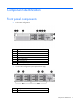
Component identification Front panel components • 8 drive SFF configuration Item Description 1 Video connector 2 Quick release levers (2) 3 SATA optical drive bay 4 SFF drive bays 5 Serial number label 6 USB connectors (2) 7 Systems Insight Display • 16 drive SFF configuration (with optional drive cage) Item Description 1 Video connector Component identification 7
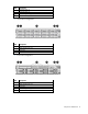
Item Description 2 Drive bays (box 1) 3 Drive bays (box 2) 4 Systems Insight Display 5 USB connectors (2) • 25 SFF drive configuration Item Description 1 Video connector 2 Quick release levers (2) 3 Drive bays 4 USB connector • 8 drive LFF configuration Item Description 1 Video connector 2 Quick release levers (2) 3 Drive bays 4 Systems Insight Display 5 USB connector Component identification 8
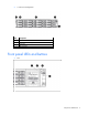
• 12 drive LFF configuration Item Description 1 Video connector 2 Quick release levers (2) 3 Drive bays 4 USB connector Front panel LEDs and buttons • SFF Component identification 9
• LFF Item Description Status 1 NIC status LED Solid green = Link to network Flashing green (1 Hz/cycle per sec) = Network active Off = No network activity 2 Health LED Solid green = Normal Flashing amber = System degraded Flashing red (1 Hz/cycle per sec) = System critical Fast-flashing red (4 Hz/cycles per sec) = Power fault* 3 Power On/Standby button and system power LED Solid green = System on Flashing green (1 Hz/cycle per sec) = Performing power on sequence Solid amber = System in standby
2. After the display fully ejects, rotate the display downward to view the LEDs. Systems Insight Display LEDs The HP Systems Insight Display LEDs represent the system board layout. The display, available on 8 SFF, 16 SFF, and 8 LFF configurations, enables diagnosis with the access panel installed. Item Description Status 1 Power cap Off = System is in standby, or no cap is set.
Item Description Status 2 NIC link/activity Off = No link to network. If the power is off, view the rear panel RJ-45 LEDs for status.
Systems Insight Display Health LED LED and color System power LED Status • • Power supply (amber) Amber Green Power supply fault System board fault One or more of the following conditions may exist: • • • • Redundant power supply is installed and only one power supply is functional. AC power cord is not plugged into redundant power supply.
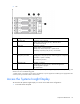
Rear panel LEDs and buttons Item Description Status 1 UID LED/button Off = Deactivated Solid blue = Activated Flashing blue = System being managed remotely 2 Power supply 2 LED Off = System is off or power supply has failed. Solid green = Normal 3 Power supply 1 LED Off = System is off or power supply has failed.
• The riser cages support a maximum power of 150 W with an HP power cable. This cable must be used for PCIe card wattages greater than 75 W.
Item Description 11 Processor 2 DIMM slots 12 Second drive cage 13 Fan connector 1 14 NMI jumper 15 Front video connector 16 Discovery services connector 17 System maintenance switch 18 SATA optical drive connector 19 SATA drive port 1 20 Power supply backplane connector 21 USB connector 22 SD card slot 23 Secondary (processor 2) PCIe riser connector 24 Processor 2 socket 25 System battery 26 TPM connector 27 Primary (processor 1) PCIe riser connector 28 Processor 1 sock
To access redundant ROM, set S1, S5, and S6 to on. When the system maintenance switch position 6 is set to the On position, the system is prepared to erase all system configuration settings from both CMOS and NVRAM. CAUTION: Clearing CMOS and/or NVRAM deletes configuration information. Be sure to properly configure the server or data loss could occur.
SAS and SATA device numbers • 8 SFF device bay numbering • 16 SFF device bay numbering • 25 SFF device bay numbering • 8 LFF device bay numbering Component identification 18
• 12 LFF device bay numbering Drive LED definitions Item LED Status 1 Locate Solid blue The drive is being identified by a host application. Flashing blue The drive carrier firmware is being updated or requires an update. Rotating green Drive activity Off No drive activity Solid white Do not remove the drive. Removing the drive causes one or more of the logical drives to fail. Off Removing the drive does not cause a logical drive to fail.
Status On = AC power is connected. Off = AC power is disconnected. Missing = Riser cage is not installed, or power might not be connected. FBWC module LEDs (P222, P420, P421) The FBWC module has three single-color LEDs (one amber and two green). The LEDs are duplicated on the reverse side of the cache module to facilitate status viewing.
1 - Amber 2 - Green 3 - Green Interpretation Off Off Off The cache module is not powered. Off Flashing 0.5 Hz Flashing 0.5 Hz The cache microcontroller is executing from within its boot loader and receiving new flash code from the host controller. Off Flashing 1 Hz Flashing 1 Hz The cache module is powering up, and the capacitor pack is charging. Off Off Flashing 1 Hz The cache module is idle, and the capacitor pack is charging.
For a single-processor configuration, four fans and two blanks are required in specific fan bays for redundancy. A fan failure or missing fan causes a loss of redundancy. A second fan failure or missing fan causes an orderly shutdown of the server. Installing more than the required number of fans in a single-processor configuration is not a supported configuration. For a dual-processor configuration, six fans are required for redundancy. A fan failure or missing fan causes a loss of redundancy.
Operations Power up the server To power up the server, press the Power On/Standby button. Power down the server Before powering down the server for any upgrade or maintenance procedures, perform a backup of critical server data and programs. IMPORTANT: When the server is in standby mode, auxiliary power is still being provided to the system. To power down the server, use one of the following methods: • Press and release the Power On/Standby button.
3. After performing the installation or maintenance procedure, slide the server back into the rack, and then press the server firmly into the rack to secure it in place. WARNING: To reduce the risk of personal injury, be careful when pressing the server rail-release latches and sliding the server into the rack. The sliding rails could pinch your fingers. Remove the server from the rack To remove the server from an HP, Compaq branded, telco, or third-party rack: 1. Power down the server (on page 23). 2.
Remove the access panel WARNING: To reduce the risk of personal injury from hot surfaces, allow the drives and the internal system components to cool before touching them. CAUTION: For proper cooling, do not operate the server without the access panel, baffles, expansion slot covers, or blanks installed. If the server supports hot-plug components, minimize the amount of time the access panel is open. To remove the component: 1.
2. Open the cable management arm. Note that the cable management arm can be right-mounted or left-mounted. Remove the fan cage To remove the component: 1. Power down the server (on page 23). 2. Remove all power: a. Disconnect each power cord from the power source. b. Disconnect each power cord from the server. 3. Extend or remove the server from the rack ("Remove the server from the rack" on page 24, "Extend the server from the rack" on page 23). 4. Remove the access panel (on page 25). 5.
6. Remove the fan cage. CAUTION: Do not operate the server for long periods with the access panel open or removed. Operating the server in this manner results in improper airflow and improper cooling that can lead to thermal damage. IMPORTANT: For optimum cooling, install fans in all primary fan locations. For more information, refer to the fan locations table ("Hot-plug fans" on page 21). To install the component, reverse the removal procedure. Remove the hot-plug fan To remove the component: 1.
3. Remove the fan. CAUTION: Do not operate the server for long periods with the access panel open or removed. Operating the server in this manner results in improper airflow and improper cooling that can lead to thermal damage. IMPORTANT: For optimum cooling, install fans in all primary fan locations. For more information, refer to the fan locations table ("Hot-plug fans" on page 21). To install the component, reverse the removal procedure.
5. If a full-length expansion board is installed in slot 1, release the full-length expansion board retainer, and then remove the primary PCIe riser cage. 6. If a full-length expansion board is installed in slot 4, release the full-length expansion board retainer, and then remove the secondary PCIe riser cage. 7. Remove the full-length expansion board. To install the component, reverse the removal procedure.
a. Disconnect each power cord from the power source. b. Disconnect each power cord from the server. 3. Extend the server from the rack (on page 23). 4. Remove the access panel (on page 25). 5. Remove any installed full-length expansion boards. 6. Remove the PCIe riser cage. To install the component, reverse the removal procedure.
5. If a full-length expansion board is installed in slot 4, release the full-length expansion board retainer, and then remove the PCIe riser cage. To install the component, reverse the removal procedure. Install the primary PCIe riser cage WARNING: To reduce the risk of personal injury, electric shock, or damage to the equipment, remove the power cord to remove power from the server. The front panel Power On/Standby button does not completely shut off system power.
5. Install the PCIe riser cage. 6. Install the access panel (on page 25). 7. Install the server into the rack ("Installing the server into the rack" on page 40). 8. Connect each power cord to the server. 9. Connect each power cord to the power source. 10. Power up the server (on page 23). Secure the primary PCIe riser cage full-length expansion board retainer 1. Power down the server (on page 23). 2. Remove all power: a. Disconnect each power cord from the power source. b.
7. Secure the full-length expansion board retainer. 8. Install the access panel (on page 25). 9. Install the server into the rack ("Installing the server into the rack" on page 40). 10. Connect each power cord to the server. 11. Connect each power cord to the power source. 12. Power up the server (on page 23). Secure the secondary PCIe riser cage full-length expansion board retainer 1. Power down the server (on page 23). 2. Remove all power: a.
7. Secure the full-length expansion board retainer. 8. Install the access panel (on page 25). 9. Install the server into the rack ("Installing the server into the rack" on page 40). 10. Connect each power cord to the server. 11. Connect each power cord to the power source. 12. Power up the server (on page 23). Remove the air baffle CAUTION: For proper cooling, do not operate the server without the access panel, baffles, expansion slot covers, or blanks installed.
6. If a full-length expansion board is installed in the secondary PCIe riser cage, release the expansion board retainer and remove the secondary PCIe riser cage (on page 30). 7. Remove the air baffle. To install the component, reverse the removal procedure.
Setup Optional installation services Delivered by experienced, certified engineers, HP Care Pack services help you keep your servers up and running with support packages tailored specifically for HP ProLiant systems. HP Care Packs let you integrate both hardware and software support into a single package. A number of service level options are available to meet your needs.
Space and airflow requirements To allow for servicing and adequate airflow, observe the following space and airflow requirements when deciding where to install a rack: • Leave a minimum clearance of 63.5 cm (25 in) in front of the rack. • Leave a minimum clearance of 76.2 cm (30 in) behind the rack. • Leave a minimum clearance of 121.9 cm (48 in) from the back of the rack to the back of another rack or row of racks.
CAUTION: To reduce the risk of damage to the equipment when installing third-party options: • Do not permit optional equipment to impede airflow around the server or to increase the internal rack temperature beyond the maximum allowable limits. • Do not exceed the manufacturer’s TMRA. Power requirements Installation of this equipment must comply with local and regional electrical regulations governing the installation of information technology equipment by licensed electricians.
WARNING: To reduce the risk of electric shock or energy hazards: • This equipment must be installed by trained service personnel, as defined by the NEC and IEC 60950-1, Second Edition, the standard for Safety of Information Technology Equipment. • Connect the equipment to a reliably grounded SELV source. An SELV source is a secondary circuit that is designed so normal and single fault conditions do not cause the voltages to exceed a safe level (60 V direct current).
WARNING: To reduce the risk of personal injury or damage to the equipment, be sure that: • • • • • The leveling jacks are extended to the floor. The full weight of the rack rests on the leveling jacks. The stabilizing feet are attached to the rack if it is a single-rack installation. The racks are coupled together in multiple-rack installations. Only one component is extended at a time. A rack may become unstable if more than one component is extended for any reason.
WARNING: To reduce the risk of electric shock, fire, or damage to the equipment, do not plug telephone or telecommunications connectors into RJ-45 connectors. 3. Connect the power cord to the rear of the server. 4. Install the power cord anchors. 5. Secure the cables to the cable management arm. IMPORTANT: When using cable management arm components, be sure to leave enough slack in each of the cables to prevent damage to the cables when the server is extended from the rack. 6.
WARNING: To reduce the risk of electric shock or damage to the equipment: • Do not disable the power cord grounding plug. The grounding plug is an important safety feature. • Plug the power cord into a grounded (earthed) electrical outlet that is easily accessible at all times. • Unplug the power cord from the power supply to disconnect power to the equipment. • Do not route the power cord where it can be walked on or pinched by items placed against it.
3. During the initial boot: o To modify the server configuration ROM default settings, press F9 when prompted from the start up sequence to enter the RBSU. By default, RBSU runs in the English language. o If you do not need to modify the server configuration and are ready to install the system software, press F10 to access Intelligent Provisioning.
Hardware options installation Introduction If more than one option is being installed, read the installation instructions for all the hardware options and identify similar steps to streamline the installation process. WARNING: To reduce the risk of personal injury from hot surfaces, allow the drives and the internal system components to cool before touching them. CAUTION: To prevent damage to electrical components, properly ground the server before beginning any installation procedure.
6. If a full-length expansion board is installed in the primary PCIe riser cage, release the full-length expansion board retainer, and then remove the PCIe riser cage. 7. If a full-length expansion board is installed in the secondary PCIe riser cage, release the full-length expansion board retainer, and then remove the PCIe riser cage.
8. Remove the air baffle (on page 34). 9. Open the heatsink retaining bracket, and then remove the heatsink blank.
10. Open the processor socket locking lever and the retaining bracket, and then remove the processor socket protective cover. IMPORTANT: Be sure the processor remains inside the processor installation tool. 11. If the processor has separated from the installation tool, carefully re-insert the processor in the tool. Handle the processor by the edges only, and do not touch the bottom of the processor, especially the contact area.
12. The processor fits one way into the socket. Use the alignment guides on the processor and socket to properly align the processor with the socket. Install the spare processor. THE PINS ON THE SYSTEM BOARD ARE VERY FRAGILE AND EASILY DAMAGED. CAUTION: THE PINS ON THE SYSTEM BOARD ARE VERY FRAGILE AND EASILY DAMAGED. To avoid damage to the system board: • Never install or remove a processor without using the processor installation tool. • Do not touch the processor socket contacts.
15. Remove the heatsink cover. CAUTION: After the cover is removed, do not touch the thermal interface media. 16. Install the heatsink, and close the heatsink retaining bracket. Be sure to align the pins on the heatsink with the pins on the processor cage.
17. Remove the fan blanks from bays 1 and 2. 18. Install the fans into bays 1 and 2.
19. Install the air baffle. 20. Install the primary PCIe riser cage.
21. Install the secondary PCIe riser cage. 22. If necessary, secure the full-length expansion board retainer for the primary or the secondary PCIe riser cages on the air baffle. 23. Install the access panel (on page 25). 24. Install the server into the rack. 25. Connect each power cord to the server. 26. Connect each power cord to the power source. 27. Power up the server (on page 23). Memory options IMPORTANT: This server does not support mixing LRDIMMs or RDIMMs.
The memory subsystem in this server can support LRDIMMs or RDIMMs: • RDIMMs offer lower latency in one DIMM per channel configurations and (relatively) low power consumption. They include address parity protection. • LRDIMMs support higher densities than single- and dual-rank RDIMMs, and higher speeds than quad-rank RDIMMs. This support enables you to install more high capacity DIMMs, resulting in higher system capacities and higher bandwidth.
Memory modules per channel Single-rank Memory module native speed or Dual-rank Memory bus speed (standard voltage memory module) Memory bus speed (low voltage memory module) Memory bus speed (ultra low voltage memory module) 3 3 mixed 1066 MHz 800 MHz 667 MHz 1600 MHz 1333 MHz Populated DIMM speed (MT/s), LRDIMM Memory modules per channel Number of LRDIMMs Memory module native speed Memory bus speed (standard voltage memory module) Memory bus speed (low voltage memory module) Memory bus spee
Memory subsystem architecture The memory subsystem in this server is divided into channels. Each processor supports four channels, and each channel supports three DIMM slots, as illustrated. This multi-channel architecture provides enhanced performance in Advanced ECC mode. This architecture also enables Online Spare Memory modes. DIMM slots in this server are identified by number and by letter: • Letters identify the population order. • Slot numbers indicate the DIMM slot ID for spare replacement.
appear as a dual-rank DIMM to the system. The LRDIMM buffer also isolates the electrical loading of the DRAM from the system to allow for faster operation. These two changes allow the system to support up to three LRDIMMs per memory channel, providing for up to 50% greater memory capacity and higher memory operating speed compared to quad-rank RDIMMs. DIMM identification To determine DIMM characteristics, use the label attached to the DIMM and the following illustration and table.
Memory configurations To optimize server availability, the server supports the following AMP modes: • Advanced ECC—provides up to 4-bit error correction. This mode is the default option for this server. • Online spare memory—provides protection against failing or degraded DIMMs. Certain memory is reserved as spare, and automatic failover to spare memory occurs when the system detects a DIMM that is degrading.
• When two processors are installed, balance the DIMMs across the two processors. • White DIMM slots denote the first slot of a channel (Ch 1-A, Ch 2-B, Ch 3-C, Ch 4-D). • Do not mix LRDIMMs or RDIMMs. • When two processors are installed, install the DIMMs in sequential alphabetical order balanced between the two processors: P1-A, P2-A, P1-B, P2-B, P1-C, P2-C, and so on.
7. Install the DIMM. 8. Install the access panel (on page 25). 9. Install the server into the rack ("Installing the server into the rack" on page 40). 10. Connect each power cord to the server. 11. Connect each power cord to the power source. 12. Power up the server (on page 23). Use RBSU ("HP ROM-Based Setup Utility" on page 103) to configure the memory mode. For more information about LEDs and troubleshooting failed DIMMs, see "Systems Insight Display LED combinations (on page 12).
1. Remove the drive blank. 2. Prepare the drive. 3. Install the drive. 4. Determine the status of the drive from the drive LED definitions (on page 19). Removing a hot-plug SAS or SATA hard drive CAUTION: For proper cooling, do not operate the server without the access panel, baffles, expansion slot covers, or blanks installed. If the server supports hot-plug components, minimize the amount of time the access panel is open. 1.
3. Remove the drive. Controller options The server ships with an embedded Smart Array P420i controller. For more information about the controller and its features, see the HP Smart Array Controllers for HP ProLiant Servers User Guide on the HP website (http://www.hp.com/support/SAC_UG_ProLiantServers_en). To configure arrays, see the Configuring Arrays on HP Smart Array Controllers Reference Guide on the HP website (http://www.hp.com/support/CASAC_RG_en).
NOTE: The data protection and the time limit also apply if a power outage occurs. When power is restored to the system, an initialization process writes the preserved data to the hard drives. Installing the flash-backed write cache module CAUTION: The cache module connector does not use the industry-standard DDR3 mini-DIMM pinout. Do not use the controller with cache modules designed for other controller models, because the controller can malfunction and you can lose data.
8. Connect the capacitor pack cable to the connector on the top of the cache module. 9. Install the access panel (on page 25). 10. Install the server into the rack ("Installing the server into the rack" on page 40). 11. Connect each power cord to the server. 12. Connect each power cord to the power source. 13. Power up the server (on page 23). Installing the FBWC capacitor pack CAUTION: The cache module connector does not use the industry-standard DDR3 mini-DIMM pinout.
8. Connect the capacitor pack cable to the connector on the top of the cache module. 9. Install one or two FBWC capacitor packs into the FBWC capacitor pack holder. 10.
o 8 or 16 drive SFF o 8 drive LFF Hardware options installation 65
• 12 drive LFF • 25 drive SFF 1. Install the access panel (on page 25). 2. Install the server into the rack ("Installing the server into the rack" on page 40). 3. Connect each power cord to the server. 4. Connect each power cord to the power source. 5. Power up the server (on page 23). Optical drive option 1. Power down the server (on page 23). 2. Remove all power: a. Disconnect each power cord from the power source.
b. Disconnect each power cord from the server. 3. Extend the server from the rack (on page 23). 4. Remove the access panel (on page 25). 5. Remove the existing media drive option or blank. 6. Slide the optical drive into the drive bay.
7. Connect the power and data cable to the system board and the optical drive. 8. Install the access panel (on page 25). 9. Install the server into the rack ("Installing the server into the rack" on page 40). 10. Connect each power cord to the server. 11. Connect each power cord to the power source. 12. Power up the server (on page 23). Redundant hot-plug power supply option CAUTION: All power supplies installed in the server must have the same output power capacity.
WARNING: To reduce the risk of personal injury from hot surfaces, allow the power supply or power supply blank to cool before touching it. 3. Insert the power supply into the power supply bay until it clicks into place. 4. Connect the power cord to the power supply. 5. Route the power cord. Use best practices when routing power cords and other cables. A cable management arm is available to help with routing. To obtain a cable management arm, contact an HP authorized reseller. 6.
To remove the component: 1. Power down the server (on page 23). 2. Remove all power: a. Disconnect each power cord from the power source. b. Disconnect each power cord from the server. 3. Remove any attached network cables. 4. Extend the server from the rack (on page 23). 5. Remove the access panel (on page 25). 6. Remove the primary PCIe riser cage (on page 29). 7. Loosen the thumbscrew. 8. Remove the existing FlexibleLOM.
To install the component: 1. Firmly seat the optional FlexibleLOM in the slot, and then tighten the thumbscrew. 2. Install the primary PCIe riser cage (on page 31). 3. Install the access panel (on page 25). 4. Slide the server into the rack. 5. Connect the LAN segment cables. 6. Connect each power cord to the server. 7. Connect each power cord to the power source. 8. Power up the server (on page 23). Expansion board options The server supports PCI Express expansion boards.
3. Extend the server from the rack (on page 23). 4. Remove the access panel (on page 25). 5. If you need to remove a blank from the primary PCIe riser cage, remove the PCIe riser cage ("Remove the primary PCIe riser cage" on page 29). 6. If you need to remove a blank from the secondary PCIe riser cage, remove the secondary PCIe riser cage (on page 30). 7. Remove the expansion slot blank. To install the component, reverse the removal procedure. Installing a half-length expansion board 1.
7. Install the expansion board. 8. Connect any required internal or external cables to the expansion board. See the documentation that ships with the expansion board. 9. Do one of the following: o Install the primary PCIe riser cage (on page 31). o Install the secondary PCIe riser cage ("Secondary PCIe riser cage option" on page 74). 10. Install the access panel (on page 25). 11. Install the server into the rack ("Installing the server into the rack" on page 40). 12.
11. o Install the primary PCIe riser cage (on page 31). o Install the secondary PCIe riser cage ("Secondary PCIe riser cage option" on page 74). Do one of the following: o Secure the primary PCIe riser cage full-length expansion board retainer (on page 32). o Secure the secondary PCIe riser cage full-length expansion board retainer (on page 33). 12. Install the access panel (on page 25). 13. Install the server into the rack ("Installing the server into the rack" on page 40). 14.
5. Remove the PCI riser blank. 6. Remove the blank from the optional secondary PCI riser cage.
7. Install an expansion board into the PCI riser cage, if needed. 8. Connect any internal or external cables. 9. Install the optional secondary PCIe riser cage. 10. If not already installed, install the secondary processor ("Processor option" on page 44). 11. Install the access panel (on page 25). 12. Install the server into the rack ("Installing the server into the rack" on page 40). 13. Connect each power cord to the server. 14. Connect each power cord to the power source. 15.
To install the component: 1. Power down the server (on page 23). 2. Remove all power: a. Disconnect each power cord from the power source. b. Disconnect each power cord from the server. 3. Extend the server from the rack (on page 23). 4. Remove the access panel (on page 25). 5. If a full-length expansion board is installed in slot 1, release the full-length expansion board retainer, and then remove the primary PCIe riser cage. 6.
8. Remove the fan cage. 9. Disconnect and remove the optical drive cable, if installed: a. Disconnect the cable.
b. Remove the cable from the DIMM guard. 10. Using a T-15 Torx screwdriver, remove the two optical drive retaining screws, and then remove the optical drive cage.
11. Install the optional hard drive cage. 12. Install the hard drives or hard drive blanks. 13. To access the cables, remove the fan bracket on the right side of the chassis. 14.
a. Connect one end of the power cable to the SAS backplane and the other end to the power connector on the system board. b. Remove the existing SAS cable from the cable guide and from the system board.
15. Connect the end of each SAS signal cable to the SAS backplane, and then route the SAS signal cables behind the cable guide. Do not connect the other ends yet. 16. Install the fan bracket. Be sure that the cables are properly routed in the channel along the fan bracket.
17. Install the fan cage. 18. Install the air baffle. If you do not have a full-length expansion board, the air baffle can be installed last.
19. Remove the blank from the PCIe riser cage. 20. Install the SAS controller board into the PCIe riser cage. 21. Connect the other end of the SAS signal cables to the SAS controller board and to the system board. Then, install the PCe riser cage.
SAS cables can be connected to the PCIe riser cage and the system board before or after the PCIe riser cage is installed. For ease in accessing connectors, HP recommends connecting the cables before the PCIe riser cage is installed. Completed SAS cabling: 22. Make sure any installed full-length expansion boards are seated in the retainer clip on the air baffle. 23. Install the access panel (on page 25). 24. Install the server into the rack. 25. Connect each power cord to the server. 26.
2U rack bezel option The 2U rack bezel helps prevent any unauthorized physical access to the server in the rack configuration. To access the hard drive cage, you must unlock and open the 2U rack bezel. To unlock the 2U rack bezel, use the key provided with the kit. Install the 2U rack bezel into the chassis, and then lock the 2U rack bezel with the key.
• When installing or replacing hardware, HP service providers cannot enable the TPM or the encryption technology. For security reasons, only the customer can enable these features. • When returning a system board for service replacement, do not remove the TPM from the system board. When requested, HP Service provides a TPM with the spare system board. • Any attempt to remove an installed TPM from the system board breaks or disfigures the TPM security rivet.
8. Install the TPM board. Press down on the connector to seat the board ("System board components" on page 15). 9. Install the TPM security rivet by pressing the rivet firmly into the system board. 10. Install the air baffle. 11. Do the following: a. Install the primary PCIe riser cage (on page 31). b. Install the secondary PCIe riser cage ("Secondary PCIe riser cage option" on page 74). 12. Install the access panel (on page 25). 13.
Retaining the recovery key/password The recovery key/password is generated during BitLocker™ setup, and can be saved and printed after BitLocker™ is enabled. When using BitLocker™, always retain the recovery key/password. The recovery key/password is required to enter Recovery Mode after BitLocker™ detects a possible compromise of system integrity.
Cabling SAS hard drive cabling • SFF hard drive cabling • SFF cabling, with optional drive cage Cabling 90
• LFF hard drive cabling Optical drive cabling Cabling 91
FBWC cabling • 8 or 16 drive SFF • 8 drive LFF Cabling 92
• 12 LFF or 25 SFF • PCIe option Depending on the server configuration, you may need to remove the primary PCIe riser cage (on page 29) before cabling to a PCIe expansion board. Chipset SATA cable option With the chipset SATA cable option, the chipset SATA controller can be used with a single SATA hard drive that is installed in one hard drive bay of the SFF or LFF hard drive cage. • When using the chipset SATA configuration, the following conditions apply: o Only drive bay 5 is enabled.
• o Hard drive status LEDs are not supported. o Hard drive thermal status monitoring is not supported. o Hot-plug operation is not supported. Because only one drive bay is enabled, all remaining drives can be removed. For proper thermal cooling, install blanks in all bays that do not have a drive installed. Order a sufficient number of 6.35-cm (2.5-in) or 8.89-cm (3.5-in) hard drive blank option kits from an HP authorized reseller. For more information, see the server maintenance and service guide.
6. If a full-length expansion board is installed in slot 4, release the full-length expansion board retainer, and then remove the secondary PCIe riser cage. 7. Remove the air baffle (on page 34). 8. Remove the fan cage (on page 26). 9. Disconnect any SAS cables from the hard drive cage and either the embedded SAS controller or an optional SAS controller. Do not disconnect the power cable.
10. Disconnect the SATA cable from the optical drive and the SATA connector on the system board. The optical bay is disabled with the chipset SATA cable option. 11. Connect the chipset SATA cable: a. Connect the chipset SATA cable connector to the chipset SATA controller port on the system board. The chipset SATA connector on the SATA cable is narrower than the chipset SATA controller port header on the system board. b.
o Secure the secondary PCIe riser cage full-length expansion board retainer (on page 33). 17. Install the access panel (on page 25). 18. Install the server in the rack ("Installing the server into the rack" on page 40). 19. Remove any installed hard drives ("Removing a hot-plug SAS or SATA hard drive" on page 60). 20. Install a SATA hard drive ("Installing a hot-plug SAS or SATA hard drive" on page 59) in hard drive bay 5. 21. Install hard drive blanks in any empty hard drive bays. 22.
Software and configuration utilities Server mode The software and configuration utilities presented in this section operate in online mode, offline mode, or in both modes.
HP iLO enables and manages the Active Health System (on page 99) and also features Agentless Management. All key internal subsystems are monitored by HP iLO. SNMP alerts are sent directly by HP iLO regardless of the host operating system or even if no host operating system is installed. Using HP iLO, you can do the following: • Access a high-performance and secure Remote Console to the server from anywhere in the world.
The Active Health System log, in conjunction with the system monitoring provided by Agentless Management or SNMP Pass-thru, provides continuous monitoring of hardware and configuration changes, system status, and service alerts for various server components. The Agentless Management Service is available in the SPP, which is a disk image (.iso) that you can download from the HP website (http://www.hp.com/go/spp/download).
HP Insight Diagnostics HP Insight Diagnostics is a proactive server management tool, available in both offline and online versions, that provides diagnostics and troubleshooting capabilities to assist IT administrators who verify server installations, troubleshoot problems, and perform repair validation. HP Insight Diagnostics Offline Edition performs various in-depth system and component testing while the OS is not running. To run this utility, boot the server using Intelligent Provisioning (on page 100).
HP Insight Remote Support software HP strongly recommends that you install HP Insight Remote Support software to complete the installation or upgrade of your product and to enable enhanced delivery of your HP Warranty, HP Care Pack Service, or HP contractual support agreement.
SPP has several key features for updating HP ProLiant servers. Using HP SUM as the deployment tool, SPP can be used in an online mode on a Windows or Linux hosted operating system, or in an offline mode where the server is booted to the ISO so that the server can be updated automatically with no user interaction or updated in interactive mode. For more information or to download SPP, see the HP website (http://www.hp.com/go/spp).
For more information on RBSU, see the HP ROM-Based Setup Utility User Guide on the Documentation CD or the HP website (http://www.hp.com/support/rbsu). Using RBSU To use RBSU, use the following keys: • To access RBSU, press the F9 key during power-up when prompted. • To navigate the menu system, use the arrow keys. • To make selections, press the Enter key. • To access Help for a highlighted configuration option, press the F1 key.
Boot options Near the end of the boot process, the boot options screen is displayed. This screen is visible for several seconds before the system attempts to boot from a supported boot device. During this time, you can do the following: • Access RBSU by pressing the F9 key. • Access Intelligent Provisioning Maintenance Menu by pressing the F10 key. • Access the boot menu by pressing the F11 key. • Force a PXE Network boot by pressing the F12 key.
10. Press the Esc key to exit RBSU. 11. Press the F10 key to confirm exiting RBSU. The server automatically reboots.
Option ROM Configuration for Arrays Before installing an operating system, you can use the ORCA utility to create the first logical drive, assign RAID levels, and establish online spare configurations.
Legacy USB support provides USB functionality in environments where USB support is not available normally. Specifically, HP provides legacy USB functionality for the following: • POST • RBSU • Diagnostics • DOS • Operating environments which do not provide native USB support Redundant ROM support The server enables you to upgrade or configure the ROM safely with redundant ROM support. The server has a single ROM that acts as two separate ROM images.
Software and firmware Software and firmware should be updated before using the server for the first time, unless any installed software or components require an older version. For system software and firmware updates, download the SPP ("HP Service Pack for ProLiant" on page 102) from the HP website (http://www.hp.com/go/spp). Version control The VCRM and VCA are web-enabled Insight Management Agents tools that HP SIM uses to schedule software update tasks to the entire enterprise.
HP Technology Service Portfolio HP Technology Services offers a targeted set of consultancy, deployment, and service solutions designed to meet the support needs of the most business and IT environments. Foundation Care services deliver scalable hardware and software support packages for HP ProLiant server and industry-standard software. You can choose the type and level of service that is most suitable for your business needs.
Troubleshooting Troubleshooting resources The HP ProLiant Gen8 Troubleshooting Guide, Volume I: Troubleshooting provides procedures for resolving common problems and comprehensive courses of action for fault isolation and identification, issue resolution, and software maintenance on ProLiant servers and server blades. To view the guide, select a language: • English (http://www.hp.com/support/ProLiant_TSG_v1_en) • French (http://www.hp.com/support/ProLiant_TSG_v1_fr) • Spanish (http://www.hp.
Battery replacement If the server no longer automatically displays the correct date and time, you may need to replace the battery that provides power to the real-time clock. WARNING: The computer contains an internal lithium manganese dioxide, a vanadium pentoxide, or an alkaline battery pack. A risk of fire and burns exists if the battery pack is not properly handled. To reduce the risk of personal injury: • • • • Do not attempt to recharge the battery.
For more information about battery replacement or proper disposal, contact an authorized reseller or an authorized service provider.
Regulatory information Safety and regulatory compliance For safety, environmental, and regulatory information, see Safety and Compliance Information for Server, Storage, Power, Networking, and Rack Products, available at the HP website (http://www.hp.com/support/Safety-Compliance-EnterpriseProducts). Turkey RoHS material content declaration Ukraine RoHS material content declaration Warranty information HP ProLiant and X86 Servers and Options (http://www.hp.
Electrostatic discharge Preventing electrostatic discharge To prevent damaging the system, be aware of the precautions you need to follow when setting up the system or handling parts. A discharge of static electricity from a finger or other conductor may damage system boards or other static-sensitive devices. This type of damage may reduce the life expectancy of the device. To prevent electrostatic damage: • Avoid hand contact by transporting and storing products in static-safe containers.
Specifications Environmental specifications Specification Value Temperature range* Operating 10°C to 35°C (50°F to 95°F) Shipping -30°C to 50°C (-22°F to 122°F) Storage -30°C to 60°C (-22°F to 140°F) Maximum wet bulb temperature 28°C (82.4°F) Relative humidity (noncondensing)** Operating 10% to 90% Non-operating 5% to 95% * All temperature ratings shown are for sea level. An altitude derating of 1°C per 300 m (1.8°F per 1,000 ft) to 3048 m (10,000 ft) is applicable. No direct sunlight allowed.
• HP 460 W CS Platinum Plus power supply (94% efficiency) (on page 117) • HP 750 W CS Gold power supply (92% efficiency) (on page 118) • HP 750 W CS Platinum Plus power supply (94% efficiency) (on page 118) • HP 750 W 48V CS DC power supply (94% efficiency) (on page 119) • HP 1200 W CS Platinum Plus power supply (90% efficiency) (on page 119) For detailed power supply specifications, see the quickspecs on the HP website (http://h18000.www1.hp.com/products/quickspecs/14209_div/14209_div.html).
Maximum peak power 460 W at 100 V to 120 V AC input 460 W at 200 V to 240 V AC input HP 750 W CS Gold power supply (92% efficiency) Specification Value Input requirements — Rated input voltage 100V to 240V AC Rated input frequency 50 to 60 Hz Rated input current 8.9A to 3.
HP 750 W 48V CS DC power supply (94% efficiency) Specification Value Input requirements — Rated input voltage -36V to -72V DC -48V DC, nominal input Rated input frequency DC Rated input current 2.
Rated input frequency 50 Hz to 60 Hz Rated input current 9.1A to 5.
Support and other resources Before you contact HP Be sure to have the following information available before you call HP: • Active Health System log (HP ProLiant Gen8 or later products) Download and have available an Active Health System log for 3 days before the failure was detected. For more information, see the HP iLO 4 User Guide or HP Intelligent Provisioning User Guide on the HP website (http://www.hp.com/go/ilo/docs).
providers or service partners) identifies that the repair can be accomplished by the use of a CSR part, HP will ship that part directly to you for replacement. There are two categories of CSR parts: • Mandatory—Parts for which customer self repair is mandatory. If you request HP to replace these parts, you will be charged for the travel and labor costs of this service. • Optional—Parts for which customer self repair is optional. These parts are also designed for customer self repair.
Pour plus d'informations sur le programme CSR de HP, contactez votre Mainteneur Agrée local. Pour plus d'informations sur ce programme en Amérique du Nord, consultez le site Web HP (http://www.hp.com/go/selfrepair). Riparazione da parte del cliente Per abbreviare i tempi di riparazione e garantire una maggiore flessibilità nella sostituzione di parti difettose, i prodotti HP sono realizzati con numerosi componenti che possono essere riparati direttamente dal cliente (CSR, Customer Self Repair).
HINWEIS: Einige Teile sind nicht für Customer Self Repair ausgelegt. Um den Garantieanspruch des Kunden zu erfüllen, muss das Teil von einem HP Servicepartner ersetzt werden. Im illustrierten Teilekatalog sind diese Teile mit „No“ bzw. „Nein“ gekennzeichnet. CSR-Teile werden abhängig von der Verfügbarkeit und vom Lieferziel am folgenden Geschäftstag geliefert. Für bestimmte Standorte ist eine Lieferung am selben Tag oder innerhalb von vier Stunden gegen einen Aufpreis verfügbar.
sustituciones que lleve a cabo el cliente, HP se hará cargo de todos los gastos de envío y devolución de componentes y escogerá la empresa de transporte que se utilice para dicho servicio. Para obtener más información acerca del programa de Reparaciones del propio cliente de HP, póngase en contacto con su proveedor de servicios local. Si está interesado en el programa para Norteamérica, visite la página web de HP siguiente (http://www.hp.com/go/selfrepair).
Opcional – Peças cujo reparo feito pelo cliente é opcional. Essas peças também são projetadas para o reparo feito pelo cliente. No entanto, se desejar que a HP as substitua, pode haver ou não a cobrança de taxa adicional, dependendo do tipo de serviço de garantia destinado ao produto. OBSERVAÇÃO: Algumas peças da HP não são projetadas para o reparo feito pelo cliente. A fim de cumprir a garantia do cliente, a HP exige que um técnico autorizado substitua a peça.
Support and other resources 127
Support and other resources 128
Acronyms and abbreviations ABEND abnormal end ACU Array Configuration Utility AMP Advanced Memory Protection ASR Automatic Server Recovery CSA Canadian Standards Association CSR Customer Self Repair DDR double data rate FBWC flash-backed write cache IEC International Electrotechnical Commission iLO Integrated Lights-Out IML Integrated Management Log LFF large form factor Acronyms and abbreviations 129
NMI nonmaskable interrupt NVRAM nonvolatile memory ORCA Option ROM Configuration for Arrays PCIe peripheral component interconnect express POST Power-On Self Test RBSU ROM-Based Setup Utility RDIMM registered dual in-line memory module RDP Rapid Deployment Pack SAS serial attached SCSI SATA serial ATA SELV separated extra low voltage SFF small form factor SIM Systems Insight Manager TMRA recommended ambient operating temperature Acronyms and abbreviations 130
TPM Trusted Platform Module UID unit identification USB universal serial bus VCA Version Control Agent Acronyms and abbreviations 131
Documentation feedback HP is committed to providing documentation that meets your needs. To help us improve the documentation, send any errors, suggestions, or comments to Documentation Feedback (mailto:docsfeedback@hp.com). Include the document title and part number, version number, or the URL when submitting your feedback.
Index A AC power supply 117, 118, 119 access panel 25 Advanced ECC memory 57, 58, 105 air baffle 34 Array Configuration Utility (ACU) 106 ASR (Automatic Server Recovery) 107 authorized reseller 121 auto-configuration process 104 Automatic Server Recovery (ASR) 107 B battery 112 BIOS upgrade 98, 107 blue screen event 17 boot options 42, 105 BSMI notice 114 buttons 7 C cable management arm 25, 40 cables 90 cabling 90, 91, 97 Canadian notice 114 capacitor pack 62, 63 Care Pack 36, 110 Change Control 110 comp
hard drive cage 76 hard drive LEDs 19 hard drives, determining status of 19 hardware options installation 40, 44 health driver 107 health LEDs 9 heatsink 44 help resources 121 hot-plug fans 21, 25 hot-plug SAS hard drive options 59 HP Insight Diagnostics 101 HP Insight Remote Support software 102, 110 HP Smart Update Manager overview 98, 103 HP technical support 110, 121 I iLO (Integrated Lights-Out) 98, 99, 100 IML (Integrated Management Log) 98, 100 Insight Diagnostics 101, 108 installation services 36 i
ROM redundancy 108 ROMPaq utility 98, 107, 108 S safety considerations 39, 108, 114 SAS and SATA device numbers 18 scripted installation 102 serial number 105 series number 114 server features and options 44 server setup 108 shipping carton contents 40 space and airflow requirements 37 specifications 116, 117, 118, 119 specifications, environmental 116 specifications, mechanical 116 specifications, power 116, 117, 118, 119 specifications, server 116 static electricity 115 support 121 supported operating sy